by Carlos Aviz, Aviz Consultoria, Francisco Reis, UERJ, Giovanni Fabris, Eletrobras, Rafael Fernandes, Unicamp, Brazil
Non-conventional Sources of Energy (NCSE) continue to be added to power grids and shift away from traditional generation based on high-inertia Synchronous Generator (SG), towards smaller and dispersed renewable sources based on SG and/or NCSE, will continue being implemented. Under fault conditions in the power system, the NCSE do not behave in the same way as large SG. The unique response of these sources to fault conditions considerably challenges traditional protection principles developed decades ago for grids with SG driving fault currents. With the increased penetration of these NCSE, traditional grid protection principles will be stressed to the point of potentially losing dependability of voltage and/or current quantities Nowadays, there is only slow progress in devising new protection principles more suitable for grids with the presence of NCSE. Line current differential or directional comparison schemes with weak infeed logic continue to work if there is enough strong NCSE in the power grid. But even more these powerful principles will face considerable performance issues if the grid is dominated by NCSE.
The application of unconventional sources is not universal and is designed specifically for a particular location and is adapted to the grid code of utilities and local regulations around the world, which is one of the main reasons for the slow progress in developing better protection principles. The NCSE time domain response depends on the control strategies model implementation of the manufactures.
It is well recognized that this non-standard fault current response time creates risk and adds cost when integrating these new sources into the grid. What is less known is that it discourages relay manufacturers from developing new relay technologies, and the relay manufacturers do not have any fixed source characteristics to work with properly.
One possible solution to this challenge could be to explore possibilities for identifying characteristics of large NCSE, primarily IBS, that can be standardized and thus give the relay manufacturers and application engineers a fixed reference to work with. It is mandatory that such common characteristics cannot violate the laws of physics or drive the cost of the source up beyond a point acceptable by the users. The IBS will not replicate a SG, but it can still respond in a consistent predicable way to fault conditions in the power grid, allowing the relay protection functions to work properly, even if the network consists only of these new sources.
Theoretical Concepts
Classification of Inverters: The inverters can be generally classified into Voltage Source Inverter (VSI) and Current Source Inverter (CSI). The VSI converts the Direct Current (DC) voltage to three–phase AC Alternate Current (AC) voltage with adjustable magnitude and frequency whereas the CSI converts the DC current to an adjustable three-phase AC current. The IBS normally produces distorted line currents and also can cause, for example, notches in voltage waveforms.
Source of Harmonics and their Main Effects: Harmonic distortions caused by the operation of loads and non-linear sources, such as wind and photovoltaic generators, cause some undesirable effects to the electrical system. These effects include reduction losses of useful life of transformers, rotating machines, capacitor banks, and others, including issues such as improper operation or complete failure of equipment, electrical losses with a consequent increase in energy consumption, effects on electrical ground connections and harmonic resonance. The effect of resonance is characterized by the non-linear variation of the equivalent impedance of an electrical system seen by a harmonic source, as a function of the frequency produced by it in the system. In the condition of electrical resonance, a circuit can present itself as a very high (parallel) or very low (series) impedance, depending on the arrangement of the circuit involved.
In these cases, harmonic voltages and currents with the limits above equipment allowed may occur, subjecting the electrical system to a dangerous operating condition. Physically, a harmonic resonance occurs at a specific frequency when an inductive reactance equates numerically to a capacitive adjacent reactance. If the two reactances seen from the injection point of the harmonic source are in series, a low impedance will be detected (series resonance). When the two reactances are in parallel, the so-called equivalent impedance will be quite high (parallel resonance). If the circuit connection is in serial or in parallel, this will depend on the point of view of the injection of the harmonic signal, as well as the system and load configuration, and this scenario can only be verified by means of computational studies of harmonic power flow. Parallel resonance occurs when the harmonic current order is generated by non-linear sources such as frequency inverters, arc and induction furnaces, photovoltaic and wind generation, for example.
Impact on Transmission Line Protection Schemes: The challenges posed by IBS to the transmission line protection schemes are multiple and proportional to the level of IBS penetration in the power grid, the control system settings and performance, the type of connection to the grid and the specific adopted protection scheme. The IBS challenges are mainly related to the following factors:
- During a fault the IBS waveform output tends to be distorted. The frequency of voltage and current can be different when compared with the pre-fault frequency and this behavior might impact the protection function algorithms to calculate the current and voltage phasor values. The phasor time response might oscillate until the fault is cleared and the power system has settled a new steady state
- Unintentionally, the IBS output frequency could be unstable and generate at an abnormal frequency with unexpected frequency rate of change
- The IBS fault current magnitude contribution will be almost nominal value as limited by the thermal rating of the power electronic components. Upon a fault, there is a transient period where the initial current is up to 2-2.5 times the IBS rating until fault detection and then reduces to a steady state value of 1.1-1.3 times rated current as the IBS control system adjusts the output according to the active and reactive power output strategy
- As aforementioned the IBS reacts to a system fault with two distinctive period, the transient and steady state period. The transient period varies between half a cycle to 1.5 cycles
- The IBS fault current sequence components, magnitude and angle, will depend on the IBS control setting and the generating conditions before the fault. The IBS control system tends to supply balance fault currents during balanced and unbalanced fault and might not provide adequate negative sequence components to be used by the protection and control elements that depends on the negative sequence quantities
Power system with a high level of renewable sources is required to maintain a satisfactory level of dependability and security as provided by SG. In the last 20 years, with the advent of Intelligent Electronic Devices (IED) and the goal to maximize the protection performance without increasing the overall secondary system cost, utilities have been working exhaustively to standardize protection schemes of the power system. Regarding the line protection scheme, the ongoing increasing request to connect new IBS has seen transmission and distribution networks to address this demand in different ways. The most important are:
- Apply the existing standard protection scheme to the IBS interconnected through Transmission Line (TL) with minimal or negligible changes
- Adjust the approved scheme to suit the specificity of the IBS and protection relay. Still the same TL scheme for both conventional and unconventional sources
- Create an ad-hoc new standard protection scheme to use for the connection of the IBS

Technical performance of any protection scheme can be analyzed according to the protection rules as dependability, robust design, selectivity and speed of operation. For all the main principles of the differential protection element used to connect IBS to the grid are kept as the main application regarding performance, reliability and dependability, providing a high level of security and dependability, being relatively immune from the magnitude of the source impedance and the number of feeders contributing to the total fault current.
As a result, the scheme can work reliably in radial application, weak infeed and in multi-ended line connection as modern differential relays can operate from 2 to 6 ended line. The scheme fits perfectly with the need posed by IBS. There are different types of differential schemes applied by relay manufactures including the traditional phase segregated scheme, negative sequence, and zero-sequence schemes. All the schemes applied different techniques to accurately synchronize current samples data from all the ends of the transmission line. Traditional phase segregated scheme provides satisfactory dependability and security performance in application with IBS.
However, in the presence of unexpected IBS output of the current magnitude and phase angle, the differential element setting and the loading condition, might need to be considered in the calculation setting philosophy. Performance of the differential element is strictly linked to the definition of the restraining signal. Challenges for the differential element might increase in islanded power system or weak areas of the network. For these applications and for earthed power system with a high impedance, the differential element sensitivity can be enhanced by enabling the zero-sequence differential scheme. Wherever the differential element is applied, schemes based on the zero-sequence component are preferred over the negative-sequence as the latest one might not reliably detect a fault. The distance protection scheme has been used for decades and is still widely implemented on IBS interconnected systems.
Despite the line differential element remains the first preference, a combination of the differential element schemes represents a cost effective and suitable solution for the line protection. The step distance element is often used as a backup protection even in application with duplicated differential element scheme. The existing literature provides an extensive coverage of the challenges, field case applications and suggestions to adopt the distance element with high penetration of IBS. Addressing the security and dependability requires the analysis of the key challenges as phase and ground distance elements applied within a protection relay.
Impact of Short-Circuit Level on Transmission Relay Protection: The transmission network protection relies on Short Circuit Level (SCL) to detect a fault to know when to operate properly. The lower values in short circuit level means that protection could take to operate or not operate as designed. This would result in longer faults on the system, posing a risk to network safety and stability. Network protection system are designed to detect, and safely isolate faulty equipment as quickly as possible, limiting the fault effects on the wider system. Protection systems are designed to have a very high degree of reliability and depend on SCL being high enough to trigger a protection relay. If the closest protection relay does not detect the fault quickly, protection further away would operate to clear the fault and this will disconnect more of the system and leave the fault on the system for longer. Typically, circuits will have main protection and one backup protection, which can be identical or different from the main one.
Maintaining a level of redundancy in protection is important to ensure a safe and reliable system; redundancy can be with different relays / functions, to avoid common cause failures. The SC reduction is not driven by a specific network change and this behavior tends to change the SCL sources across the system. This affects the protection in different location of transmission lines.
Impact of Short-Circuit Level on Phase-Locked Loop – PLL Converter: A PLL is a control loop used in inverter control systems to track the phase angle of the grid. Successful tracking of phase angle results not only in a successful synchronization of the inverter with the grid, but also allows the inverter control system to adequately decide the necessary angle required for its terminal voltage in order to inject current into the network. Operation of the PLL closed loop can be related to the natural interaction that occurs between the rotor angle of a SG and its terminal voltage angle. The PLL are a converter technology commonly used on NCSE such as wind, solar and HVDC systems. The SCL is required to maintain a stable voltage during a fault period informing the PLL converters. The reduction in SCL means that the PLL converters may not keep reference with the system during a fault period.
The system with multiple generators will be affected by a fault adversely, and the converter uses the angle phase information to know what is happening on the system and to know if it needs to change its output. The PLL plays an important role in keeping converters connected to the system during normal operation and during a fault condition. SCL is important during a fault as it helps to maintain one stable voltage. As SCL reduces the voltage waveform will become more disturbed during a fault, and can compromise the PLL algorithms, depending on the design and strategy of control system adopted by the manufacture.
Impact the Short-Circuit Level on the whole System: When the SCL reduces, the transmission system will have an impact on distribution SCL. As opposed to, when there is an increase in the SCL contribution at the distribution system, from the growth of distributed generation, there is also a declining from the transmission contribution. Increasing the SCL at the transmission level, would be more effective than at distribution to solve transmission issues. Distribution systems are expected to verify an increase in demand and distributed generation which will increase their maximum SCL. On the transmission system it’s expected to have a decrease in SCL due to the reduction in the synchronized SG. These two trends cause effects on the SCL behavior on the transmission and distribution system. On the distribution system, the network effect is that the maximum SCL is increasing with the contribution from distributed generation, and this may drive asset investment. The minimum SCL on the distribution reduces as the contribution from transmission SCL decreases. On the transmission system, the contribution to SCL from distribution system is small, but it´s increasing.
Impact of Fault Calculation Programs for Wind Turbine Generators: As the penetration of wind farms increases, there is an urgent need to improve the commercial steady-state short-circuit programs to accommodate the unconventional fault response of WTG, especially Type-III and Type-IV, where the controls implemented by WTG manufactures will depend on their own technology. As mentioned, a tabular approach is proposed that defines the current output and power factor angle of the machine at different terminal voltages, both positive and negative sequence, at different time-frames, for various control modes implemented by the manufacturer. This is the most general approach, and the manufacturers have agreed to provide such data as soon as possible. Software developers have shown that this approach can be integrated in their existing short-circuit programs by treating the WTG as a nonlinear element with output characteristics.
Secondly, generic EMT models can be used to validate against available field data. Phasor domain models are developed by EPRI based on these validated models. These are also integrated by software developers. However, there is no guarantee that the fault response of these models can cover all the different scenarios. Further testing of the software models on actual utility systems with varying penetration of renewable sources and standardization of fault response by grid codes and/or industry standards are expected to contribute to refinement of the software-models implemented in the manufacture´s products.
Simulation and Results
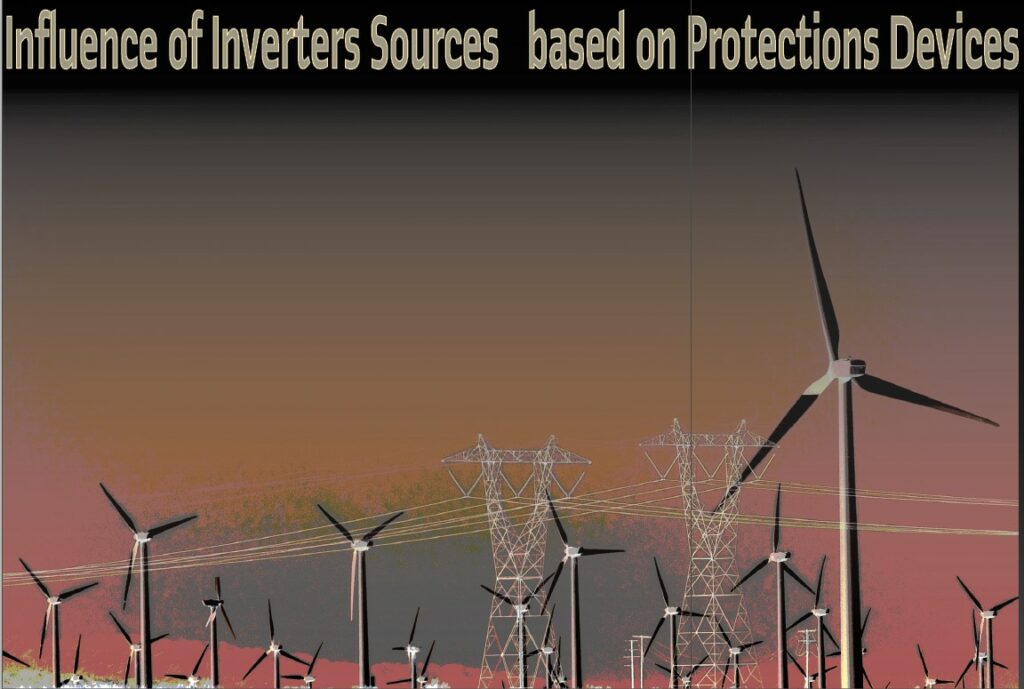
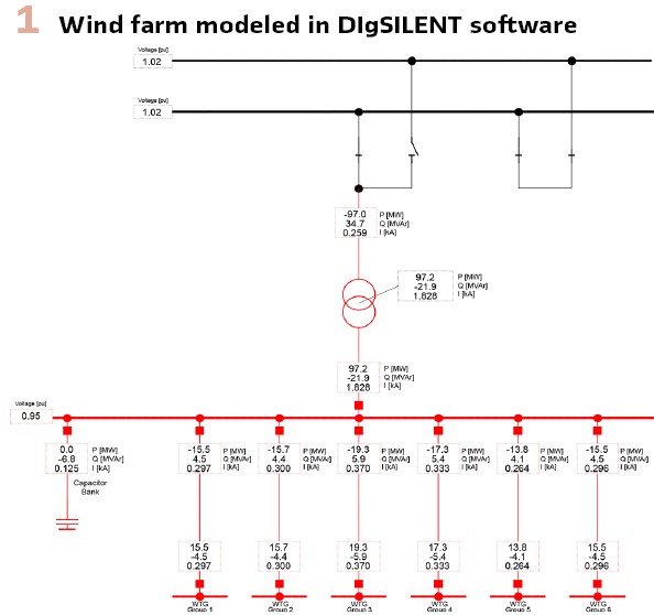
Simulation of one Wind Fam using a EMT Tool: In Figure 1, is shown one wind farm modeled in the DigSILENT software, where it´s possible to verify the AC 230 kV network, capacitor bank in the 69 kV side (reactive power compensation P/Q and Q/V curves) and the wind farm equivalent in the 0.69 kV side. The system was modeled considering two wind farms, with 100 MW each one. In Figure 2, there is the Group 1 of the wind farm. The models used for the WTG were in accordance with benchmarking system available from DIgSILENT.
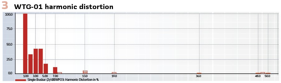
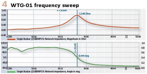
Each WTG was modeled also considering inter-harmonic content in accordance with IEC 61000 standard limits. In Figure 3, there is the voltage harmonic distortion of the WTG-01, considering the fundamental frequency as 60 Hz. In Figure 4, there is the harmonic resonance (parallel resonance) of the WTG-01 (magnitude and angle).
Thus, it is important to model the WTG in one EMT software considering not only the inter-harmonics, but also the subharmonics, otherwise it would not be possible to verify the impact of these subharmonics into the network during the simulation, for example.
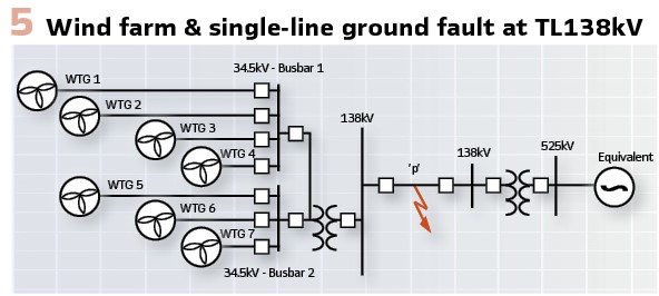
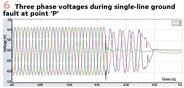
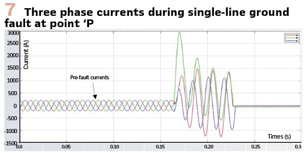
Real Disturbance Presentation in the BIPS: Figure 5 corresponds to the single-line diagram of a 138kV transmission line close to a wind farm with an installed capacity of 164 MW, where the single-phase short-circuit at point P stands out. This event occurred in the Brazilian Interconnected Power System (BIPS). Figures 6 and 7 show the behavior of voltages and currents during the short-circuit event, with the total pre-fault current being lower than the rated current of inverters.
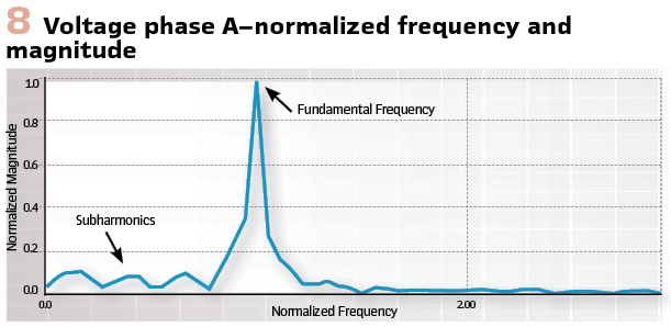
- Spectral Analysis: In Figure 8, there is the spectral analysis using Fourier Transform (FT) of voltage phase A during the whole period of the signal. It is possible to verify the presence of subharmonic orders around 6 Hz, 20 Hz and 30 Hz, respectively, and magnitudes around 10% of fundamental frequency of 60 Hz
As the relay will work with one sliding FT window, it would be able to catch these 3 fault cycles, however, to perform the harmonic content, for example, the subharmonic of order 5 Hz, it would be necessary to have one sliding window size of 60Hz / 5 Hz = 12 data cycles, and the protection relays, normally, working with one sliding window, considering 1 or 3 data cycles, for example, depending on the digital processing strategies of each manufacture. If the relay works with one sliding window of 12 data cycles, for example, in the first fault cycle, it will have 11 pre-fault cycles plus 1 fault cycle, and then it would discriminate the subharmonic. In the second estimation it would “slide” the samples discarding the oldest one and updating the newest one from the second fault cycle, then estimating the subharmonics until the circuit breaker opens.
The problem is that if the protection relay delay does this, i.e., it works with a window size of 12 data cycles, their processing will include delay. Thus, nowadays, protection manufacture relays via FT with only 3 data cycles cannot precisely discriminate the subharmonic contents. In case the protection relay is not able to discriminate the subharmonics, working with only the 3 data cycles, for example, these subharmonics will appear in the signal as DC shift and this will influence, depending on the magnitude of the subharmonic, the algorithms of fault location, infeed/outfeed, under/overreach, and loop selection of the relay. Concluding this approach, the window size needed to discriminate the subharmonic is a 3-cycle window, which is commonly used by most relay manufacturers, and impacts on the errors of the protection algorithms.
General Recommendations
Complex Generator Interconnection Process and Modeling and Studies: Inconsistent modeling and study requirements, lack of clarity at time of request and changes in equipment and settings throughout the process. Short timeline to run detailed studies, if needed. Lack of transparency and “sign-off” on critical decisions. Lack of mutual agreement and understanding about equipment settings and detailed models. Process improvements needed and difficult for both generation and transmission sides.
Growing List of Modeling Issues: Transmission entities taking models at face value with no analysis of model quality. Unintentionally incorrect models (parametrization) used and never questioned. Intentionally incorrect models used to get through interconnection process easily. There is a lack of technical expertise in companies to detail EMT models and analyze vast number of models for interconnection requests. Interconnection studies not picking-up reliability issues with positive sequence studies mostly, will not identify transient problems. Furthermore, detailed EMT studies without accurate models of protection and inappropriate use of EMT models, or overestimation of model quality, will bring wrong results.
Studies disabling protection and modifying controls without systemic modeling errors during interconnection and in planning studies with defaults models used in interconnection studies, never get updated or restudied during interconnection process. Generator owners making changes to equipment without seeking prior approval (models not getting updated).
Protection Settings: Inverter protection should be set based on equipment limitations and sets minimum performance requirements. Frequency related tripping should use accurately measured frequency over a time window. Inverter sub-cycle overvoltage protection should be set as high as possible within equipment limitations. Specify performance during successive fault events.
The ROCOF protection should be disabled unless equipment limitation exists. Distance relays with instantaneous device, installed close to the NCSE, must have their settings checked, evaluated and tested using properly specific software programs. As an example of a problem, it is observed that the frequency of voltage and current, at the time of the fault, being different from the pre-fault, can cause challenges in memory polarization. By incorrectly measuring the frequency during a fault, memory polarization can gradually become incorrect over time.
Power Quality: Specify outage scenarios for IBS to assess power quality impacts and may request grid harmonic impedance characteristics from utilities. Reactive facility data and measure background power quality prior to interconnection for design reference and later power quality responsibility separation. Permanent power quality monitoring recommended for commercial operations and characterized actual harmonic distortion performance during trial operation when plant commissioning and prior to commercial operation. Any issues should be addressed based on requirements established by utilities.
Conclusions
This work made a contribution about the impact on electrical protection systems against non-conventional energy sources, particularly solar and wind sources. It also addressed, in an informative way, the challenges to be faced in the operation in view of the increasing presence of converters in the power grid. certain phenomena in the power grid, such as the presence of subharmonics, should be monitored in real time and new digital signal processing techniques, in addition to the fourier transform – commonly used in electrical protection relays, should be studied, tested, implemented and validated, in order to bring more reliability of the phasor protection functions.
Biographies:

Carlos Alberto de Miranda Aviz is natural of Sao Paulo Brazil. Electrical Engineer graduated and Pos graduated. Expert in protection, supervision and control of electrical system. Retired after thirty-eight years dedicated to developing solution for Operation and Maintenance of main Hydroelectric, Wind and Solar plants of North and Northwest- Brazil. Coordinator of several work groups for specific protection solutions for both deployment and modernization. Nacional Delegate IEC TC95 MT4 and Secretary of Cigre´s WG B5.65 for better orchestration of Influence Inverters Based Sources on Protection Devices.

Francisco Antonio Reis Filho holds a degree in Electrical Engineering from UVA (1981), a master’s degree in Electrical Engineering from the University of São Paulo (1993) and a PhD in Electrical Engineering from the University of São Paulo (2002). He has more than 40 years of experience in the area of Power Systems acquired at FURNAS, ABB, GE, SEL and SEG, focusing on Protection of Electrical Systems and electrical studies in general. He currently works in consulting, teaching and research activities.

Giovanni Baptista Fabris – Born in Criciúma/SC – Brazil, in 1979. Electrical Engineer from the Federal University of Santa Catarina UFSC (2002) and Specialist in Electrical Systems Protection from the Federal University of Rio de Janeiro – Escola Politécnica UFRJ (2005). He is currently pursuing a master’s degree from the Federal Institute of Santa Catarina (IFSC). He works as an Electrical Power System Studies Engineer at the Operation Engineering Division (DEOP), at the System Operation Department (DOS), at ELETROBRAS CGT ELETROSUL, since 2002.

Rafael de Oliveira Fernandes is an experienced Power System Engineer with a demonstrated history of working in the electrical power system & energy industry. Skilled in Power Transmission, Power Plants, Smart Grid, Control Systems Design, and Electrical Wiring. Strong engineering professional with a bachelor’s degree focused on Electrical Power Systems from Federal University of Itajubá – UNIFEI/MG, Master’s Degree from UNICAMP University with Dynamic Stability using PMU and currently is taking his PhD Degree in the area involving Electromagnetic Transient from UNICAMP University.