By Chu Cheng, and Randall Kimura, (retired), AltaLink Management Ltd, Canada
AltaLinkhas traditionally installed P&C systemsbased on engineering standards. These standards utilize copper connections, for analogue signals, from the primary equipment in the switchyard to IEDs, such as protective relays and RTU, in the substation control building. Copper wiring is also used to connect digital signals, such as trips, controls and alarms, from the primary equipment to IEDs and RTUs.
Design, installation, testing and commissioning of copper cables requires a significant amount of time. Cable trenches are required to run the cables between primary equipment and the control building. A large quantity of terminations also presents opportunities for mistakes, thereby, making commissioning a time-consuming process to ensure that all cables have been terminated correctly.
Since these are point-to-point connections, any changes in the future require similar resources as above. Utilization of point-to-point connections does not allow for integration between protection IEDs and SCADA equipment which results in further increase of resourcing requirements. All the wiring interconnections are currently performed at site thereby requiring expensive labor. Safety considerations are also significant in this design due to all the terminations which may result in workers being exposed to live voltage circuits and open CT circuits. It is not possible to monitor these circuits which results in significant maintenance costs.
AltaLink
Headquartered in Calgary, with offices in Edmonton, Red Deer and Lethbridge, AltaLink is Alberta’s largest electricity transmission provider. AltaLink is partnering with its customers to provide innovative solutions to meet the province’s demand for reliable and affordable energy. A wholly owned subsidiary of Berkshire Hathaway Energy, AltaLink is part of a global group of companies delivering energy services to customers worldwide. Learn more at www.altalink.ca.
AltaLink, Canada’s only fully independent transmission provider, is responsible for the maintenance and operation of more than 13,000 kilometers of transmission lines and approximately 300 substations in Alberta.
BLACKIE Substation
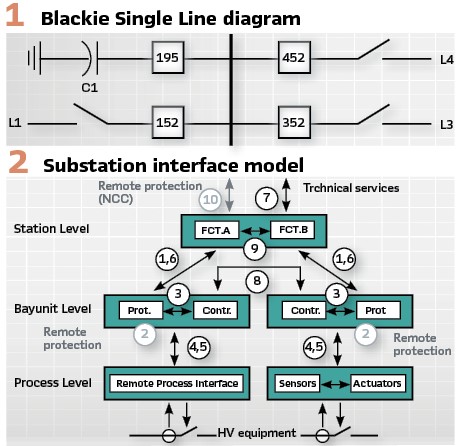
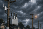
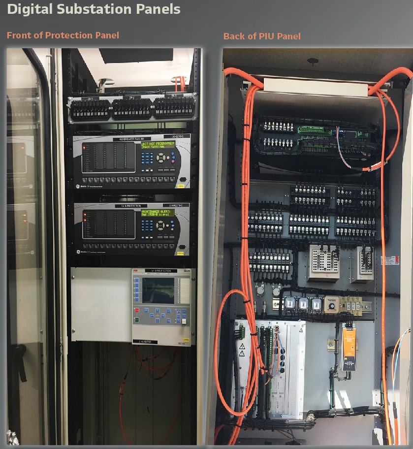
In 2017 AltaLink started work to develop and deploy a digital substation leveraging a control building replacement project. This project includes installing new protection relays and SCADA equipment while maintaining the existing primary equipment and telecom infrastructure. The substation is a 138KV switching station with three lines, one capacitor bank, and one bus. (Figure 1).
Technologies
There are existing technology concepts in the industry which allow information between IEDs and RTUs to be exchanged in a digital format over LAN. These concepts are supported by standard protocols such as DNP and IEC 61850 or proprietary vendor protocols. AltaLink has not adopted these protocols as a standard for exchanging information between IEDs but a few pilots have been performed.
The pilot project goal is to replace point to point copper connections with digitized solutions utilizing substation networks. All technologies, IEC 61850 and additional technologies, were considered for the pilot project.
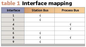
Architecture: Figure 2 is the IEC 61850 interface model of a substation automation system. Table 1 summarizes the logical interface mapping to the physical interfaces.
During the equipment evaluation two methods of interconnecting process level devices to bay level devices are available:
- A manufacturer agnostic IEC 61850 process bus architecture system and
- A proprietary point to point system.
The IEC 61850 process bus system leverages manufacturer interoperability thereby providing the most value and flexibility. Proprietary point to point systems eliminates manufacturer interoperability thereby removing flexibility and reducing the value of the solution. Although the IEC 61850 process bus solution is preferred, the pilot project will use two separate protection systems.
Communications: DNP3 has been used in AltaLink as the standard for communication between the substations and the control centers. Modification of the EMS and system front end is outside the scope of the pilot project.
Within the substation the RTU functions as a data concentrator between the control center and substation devices (e.g. SCADA I/O, protection meter, etc.). The RTU supports a DNP3 client while the substation devices support DNP3 servers. The pilot project transitioned to MMS with an RTU MMS client and servers in the substation devices.
Time sensitive information (e.g. protection tripping commands) are a high priority and therefore require a reliable method of communication. GOOSE is the mechanism for distributing status information in the digital substation environment. The GOOSE information is published as multicast messages without being addressed to a specific receiver. This information is then distributed across the station bus network allowing any IED to receive it. Row 3 in Table 3 summarizes the GOOSE capabilities of the protection relays evaluated for the pilot project.
Sampled values transmit digitized power system values, for example current and voltage, from the switchyard to the control building. Digitization enables replacement of the copper cables between the switchyard and control building with fiber optic cables.
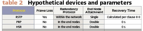
PRP: IEC 61850-90-4 describes three level 2 redundancy protocols for network redundancy; RSTP, PRP, and HSR. IEC 62439-1 provides a comparison of these redundancy protocols. Table 2 is a summary of the redundancy protocol comparison in IEC 62439-1.
Seamless network recovery (i.e. zero recovery time and no frame loss) is required for sampled values, therefore only PRP and HSR will be accepted for an interoperable process bus solution.
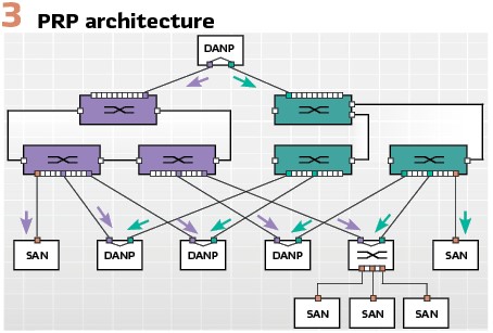
Doubly attached nodes (DANs) are preferred to singly attached nodes (SANs). A SAN has one network port with additional hardware required to interface with a PRP or HSR system. DANs support two network ports (i.e. doubly attached) natively supporting redundancy. A doubly attached node supporting PRP is referred to as a DANP while a doubly attached node supporting HSR is referred to as DANH. (Figure 3).
PRP was selected as the redundancy protocol for the station bus network, therefore preference was given to devices which supported PRP. When it was not possible to obtain a PRP capable device, a redundancy box (RedBox) was used. This, however, only applied to non-protection devices. We required all protection devices to be double attached nodes. This distinction emphasizes the requirement for no single point of failure while protecting the primary equipment.
Time Synchronization: Precision Time Protocol (PTP) was developed to simultaneously synchronize several devices on LAN with sub-microsecond accuracy. The protocol was developed to fill a void left by previous technologies. Network Time Protocol (NTP) was not accurate enough to meet a lot of industries technical requirements and multiple GPS receivers in the system is not a cost-effective solution.
IEEE 1588v2 PTP was selected as the preferred time synchronization method. All PTP capable devices are time synchronized to a PTP source except for one manufacturer. It was observed that the equipment from this manufacturer does not continuously synchronize to the PTP source and thus switched to IRIG-B.
Equipment Selection
AltaLink has approved manufacturers for protective relays, networking equipment, and satellite clocks. Additional manufacturers and device models were included in the pilot project equipment evaluations.
Protection Relays: Manufacturer A, B and C in Table 3 supply the existing protective relaying equipment used by AltaLink. Manufacturer C did not supply equipment for testing and was excluded from the evaluation.
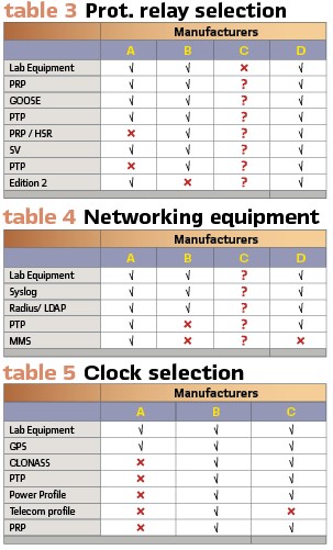
Manufacturer A is limited to a proprietary point to point solution between the control building and switchyard. Manufacturer D is an IEC 61850-90-4 HSR based process bus solution. Manufacturer B offers two solutions; a proprietary point to point and IEC 61850-90-4 PRP based process bus. IEC 61850 Edition 2 support is required for station bus interoperability; therefore, manufacturer A and D were selected.
Networking Equipment: Manufacturer A and B in Table 4 supply the existing substation networking equipment used by AltaLink. The Ethernet switch supplied by Manufacturer C repeatedly failed in the lab. Manufacturer C recommended using a product from a different business unit. The second Ethernet switch was less reliable than the original switch tested. The problems were not resolved, and the lack of operational units resulted in Manufacturer C products being excluded from the evaluation.
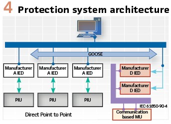
The absence of PTP transparent clock support excluded Manufacturer B. Manufacturer A and D are used for separate PRP channels (shown in green and purple channels in Figure 4).
Clock: Initially AltaLink used IRIG-B for SCADA and disturbance monitoring, and NTP for event logging time synchronization. In 2016 AltaLink deployed a pilot project using PTP grandmaster and boundary clocks to fulfill 1 millisecond accuracy requirements. The digital substation requires enhanced accuracy for sampled values. The time synchronization requirements for sampled values are specified in IEC 61869-9:
the accuracy of the time signal (mean error from absolute time) is expected to meet or exceed the IEC 61850-5 Ed. 2.0 performance class T5 with 1 μs accuracy.
Manufacturer A and B in Table 5 supply the existing substation clocks used by AltaLink. Manufacturer B supplies the clock used for the initial PTP pilot.
The substation clock supplied by Manufacturer B was selected for the digital substation pilot.
Time synchronization becomes a major factor in the implementation of process bus. The substation clock is considered a component of the protection system and the use of two different manufacturers is preferred.
Solution
AltaLink conventional 138KV protection design includes line, bus and breaker control protective relays. Trip commands are wired into the breaker control circuits. Alberta System Electric Operator (AESO) section 502.3 mandated two independently operating protection systems. AltaLink deployed protective relay manufacturer A and D at Blackie to fulfill this requirement. Conventionally noted as protection system A and B for manufacturer A and D respectively. Redundancy for the bus protection and bay controller is not a requirement for 138KV.
Protection system A, shown in black in Figure 4, consists of a line protection relay, breaker controller relay and process interface unit per bay. Protection system A uses a proprietary point to point system between process interface unit (PIU) and protective relays. Protection system B, shown in red in Figure 4, consists of line and bus protection relays, merging unit (MU) and a remote I/O unit per bay. Protection system B uses IEC 61850-90-4 HSR based process bus.
AltaLink’s current RTU manufacturer supports both PTP, and IEC 61850 Edition 2. For redundancy, two RTU’s are loaded with the same configuration and operate in hot standby for seamless failover. Alarms and controls are communicated digitally via MMS, between the RTU and protection devices. Some alarms remain hard-wired, those are converted by a digital I/O box.
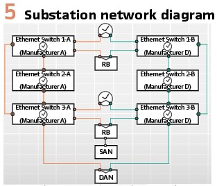
Six Ethernet switches are installed from networking equipment manufacturer A and D, constructing a fully redundant system with three pairs of Ethernet switches. One pair of switches is dedicated to process bus for protective system ‘B’, the other pair used for protection system ‘B’ station bus, and the third pair used for protection system ‘A’ station bus. The process interface for protection system ‘A’ is a point-to-point system which does not require networking equipment. The networks are physically connected, information is segregated using VLAN’s. (Figure 5).
Accurate and robust time synchronization is a critical component for the reliable operation of a protection system in a digital substation. The pilot project includes two clocks with individual antennas to provide a redundant source of time to the system. PTP is used as the primary time source at Blackie. An IEC 61850 T4 Class 4 microsecond accuracy is required for this application. The Best Master Clock Algorithm (BCMA) is used to set priorities on each clock. The clocks utilize PRP to connect to both sides of the PRP network. Redundancy boxes are used to connect SANs while DANs connect to each side of the network. The Ethernet switches are all configured as transparent clocks.
Protection manufacturer A relay and PIU must be configured as a point-to-point system. It is believed the protection relay operates as a boundary clock to the PIUs therefore PIUs are not explicitly synchronized by the external clocks. Testing showed the two protection relay manufacturers process PTP and respond to PRP failovers using different approaches, resulting in differences in the timing of protection relays. A comparison was performed against additional manufacturers and it was observed the behavior of Manufacturer A differed. Similar test was performed comparing IRIG-B and it was observed the Manufacturer A IRIG B implementation is more accurate. This left no choice for AltaLink but to implement additional hardware for IRIG-B time synchronization to manufacturer A relays.
Protection Operations
Following energization in 2018, Blackie experienced three independent faults on 138KV transmission lines. First fault experienced by L1, due to failed structure top arm. Second fault experienced by L4, also due to failed top arm. The most recent fault occurred on L3.
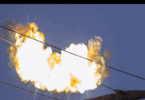
Fault #1: On January 15, 2019 approximately 10pm, L1 tripped on a B-C fault. It is suspected adverse weather condition combined with possible contamination from industrial plants in the area caused fault on the arm and ultimately the arm failed. The faulted arm is located approximately 36 kilometers away from Blackie. (Figure 6).
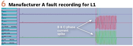
Manufacturer A and Manufacturer D line protections for L1 identified and operated correctly for the fault. Manufacturer A issued a trip after timing out 0.35 second zone 2 delay, and PIU received the trip command within 4.2ms followed by trip output contact operation in 35.5ms. Manufacturer D also issued a trip after timing out 0.35 second zone 2 delay. Remote IO (RIO) received a trip GOOSE message in 4ms, trip output contacted operated in 26ms.
Breaker failure protection relay from manufacturer A received break failure initiate and reclose initiate from both line protections. Reclose cycle began timing as programmed. Blackie is the follow end and can only reclose following live-line detection. Lead end attempted reclose as per design but failed to hold as arm failure persisted to be a permanent fault. Blackie reclose locked out due to unsuccessful reclose. AltaLink control center then attempted manual close from Blackie, causing the relay to operate again on Switch-onto-fault. Breaker 152 did open successfully; breaker failure protection was initiated but did not operate.
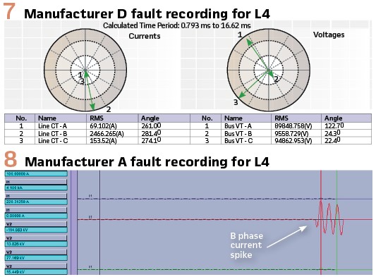
Fault #2: On March 24, 2019 at approximately 12:07am, L4 tripped on a B-G fault due to failed top arm. The faulted structure is located 1.1 kilometer away from Blackie.
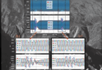
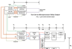
Manufacturer A and Manufacturer D line protections operated and identified the fault correctly for L4. Manufacturer A detected the fault in zone 1, and issued a trip immediately, PIU received the trip command within 2.2 millisecond followed by trip output contact operation in 12.5 millisecond. Manufacturer D also issued a trip immediately with zone 1 fault. RIO received a trip GOOSE message in 1 millisecond. (Figures 7 and 8).
Breaker failure protection relay received breaker failure initiate and reclose initiate from both line protections. Reclose cycle began timing as programmed. Lead end attempted reclose as per designed but failed to hold as arm failure persisted to be a permanent fault. Blackie is the follow end and eventually locked out due to unsuccessful reclose. Breaker 452 opened successfully; breaker failure protection was initiated but did not operate.
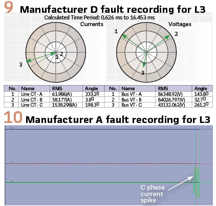
Fault #3: On June 10, approximately 2 AM L3 tripped on a C-G fault. The fault was located 30.4 kilometer away from Blackie. Manufacturer A and Manufacturer D line protections operated and identified the fault correctly for L3. Manufacturer A detected the fault in zone 1, and issued a trip immediately, PIU received the trip command within 4.2 millisecond followed by trip output contact operation in 27.7 millisecond. Manufacturer D also issued a trip immediately with zone 1 fault. RIO received a trip GOOSE message in 4 milliseconds. (Figures 9/10).
Breaker failure protection relay received breaker failure initiate and reclose initiate from both line protections. Reclose cycle began timing as programmed. Blackie is the lead end for L3 and reclosed unconditionally following 3 second programmed timer. The fault was temporary and reclose for L3 was successful.
Lessons Learned: The digital substation concept was proven successful at Blackie, however additional challenges surfaced during fault analysis. Manufacture A and Manufacture D are using two different timing sources: IRIG-B and PTP respectively. IRIG-B and PTP have inherently different accuracies, resulting in minor timing differences between two protection systems. Manufacturer A event reporting time stamp is reported to the microseconds while manufacturer D event report time stamp is reported to milliseconds. Different manufacturer event time stamp combined with different clock sources causes protection system performance difficult to compare between the two manufacturers. For example, a GOOSE message from Manufacturer A may be published at 00:00:00.10001 and received by Manufacturer D at 00:00:00.100 suggesting GOOSE message was received before publishing. For a large event with multiple entries, it would be difficult to clearly correlate publication and reception of signals.
Protection system using Manufacture A and Manufacturer D are said to operate independently except for breaker failure protection. Breaker failure protection is only implemented in one Manufacturer A relay. Three faults at Blackie all showed Station Bus communication between Manufacturer A devices are extremely fast, between publication and reception the time is less than 100 microseconds. Communication between Manufacture A and Manufacturer D is approximately 1 to 4 milliseconds. Although GOOSE communication timing is relatively small compared to overall protection operation, one would not expect such a large difference on Station Bus communication between devices from the same manufacturer and devices between different manufacturers.
Manufacture D is a new manufacturer for AltaLink protective relays. During design, signals were used to initiate event recording and oscillography recording but later determined to be excessive. Unnecessary triggering of fault report caused useful fault data to be overwritten by irrelevant system events. Settings has been changed on Manufacturer D relays to reduce event triggering to avoid the issue.
Conclusion: As AltaLink takes a step towards a networked architecture migrating away from copper wired systems, we realize the convergence of various technologies on common platforms. Blackie was successfully energized in November 2018, and successfully operated for three-line faults up to date.
Biographies:

Chu Cheng graduated in 2014 from University of Calgary with a Bachelor of Science degree in Electrical Engineering. Chu worked in AltaLink as a Protection & Control engineer in AltaLink Asset Management and is currently a Protection & Control engineer in project development. Chu focuses her work on high voltage protection and control setting design and testing involving transmission line protection, transformer protection, and various high voltage equipment protection. Chu is a member of the IEC TC57 Working Group 10. She is a registered Professional Engineer in the province of Alberta.

Randall Kimura, P. Eng. received his Bachelor of Science and Master of Science in Electrical Engineering from the University of Alberta. His 30+ years of work experience ranges from developing SCADA applications and communication protocols to System Engineering for domestic and international substation automation projects. Prior to his retirement from AltaLink in 2020 Randy was a member of the IEEE Power and Energy Society, the Power Energy Automation Conference organizing committee, several IEC TC57 Working Groups (10/15/17), and several IEEE PSCC subcommittees.