By Andres Rodriguez and Carlos Polanco, ENEL Codensa, Colombia, and Ivan Otarola and Julder Uzcategui, SOLTEC Soluciones Teleinformaticas y Control, Peru/Venezuela
During the last years there has been a growth in the implementation of fully digital protection, automation and control (PAC) system based on IEC 61850 around the world. As a result, the digitalization in electrical substations is being accepted for most electrical utilities since it has been proved to be reliable and secure.
With digital substations, the wired system of a conventional substation has now been converted to “digital wiring” translated into GOOSE, SV, PTP and MMS messages in the PAC system. This scenario increases the possibility to use redundancy techniques improving the reliability and availability of the PAC system since the amount of physical wiring (hard-wired and communication) can be optimized and the devices are able to easily subscribe to the desired information published in the process or station bus without the necessity of additional physical wiring. This article focuses on the redundancy techniques implemented in the PAC system of Portugal Digital Substation, property of ENEL Codensa, a Colombian electrical utility
The Portugal digital substation (115/11,4 kV) is located in Colombia, in the department of Cundinamarca, town of Suba. It is responsible for providing the energy necessary for the operation of the Salitre Wastewater Treatment Plant (PTAR Salitre), which is helping to decontaminate the Bogota River. This substation was commissioned in November 2020 and was the first fully Digital Substation commissioned in Colombia according to the standard IEC61850-9-2LE, using GOOSE, SV and MMS messages as well as PTP synchronization through a shared process and station bus separated by VLAN and Multicast filters.
This article describes and shows the results of redundancy techniques applied in the PAC system of Portugal Digital substation enumerated in the following parts:
- Level 0, hardwiring redundancy: Optimization of the amount of hardwiring distributed in the Merging Units to achieve a redundant level 0
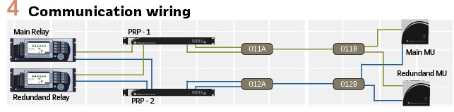
- Communication wiring redundancy: Details on how the redundant communication wiring for process/station bus was designed for the PAC system
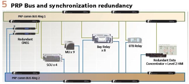
- Process/Station Bus and synchronization redundancy: How the use of PRP/RSTP and PTP redundancy ensure the high availability of the PAC system
- Level 1, SV and GOOSE message redundancy: The use of SV and GOOSE subscribed by the protection relays taking advantage of the redundant messages in the shared bus and using applications as Cross-checking and programmable logic, improving the conventional reliability of the PAC system
- Level 2 and 3, MMS integration redundancy: The use of redundant MMS integration in the Data Concentrator and using applications as Redundant I/O, Programmable Calculator and Input Point suppression achieving a high availability and reliability of the supervision and control from the local HMI and the ENEL Codensa Control Center
Description of Portugal Substation
Portugal Substation consists of four bays of 115kV simple busbar, AIS type, two transmission lines in 115 kV connected to SET Noroeste and SET Tibabuyes, one feeder in 115KV to PTAR Salitre and a power transformer bay 115 /11,4 kV.
The features of the PAC system are:
(1) Fully digital and redundant architecture according to the standards IEC61850-9-2LE, IEC61850-8-1, IEEE1588 v2 PTP and IEC 62439-3 PRP.
(2) One unique redundant communication bus PRP shared by process bus and station bus separated by VLAN and multicast filters. It is composed of two 4-switch rings using 1 Gb/s interfaces. Each switch has 68 Gb/s of switching capacity
(3) The VLANs in the communication bus are independent for each Service: Sampled Values, GOOSE, PTP, MMS and IEDs management, and using QoS (quality of service) and CoS (Class of service) functions. These services are differentiated with different priorities for the network traffic management according to the recommendations of the technical report IEC61850-90-4
(4) For time synchronization application, the bus has two GNSS (Global Navigation Satellite system), each with GPS + GLONASS service and compliance with IEEE1588 v2 PTP and IEC 62439-3 PRP standards
(5) Redundant Merging Unit and redundant protection relay for each bay and a busbar protection relay
(6) The Merging Units and SCU units are located near field devices (approximately 3 meters). They are compliance with the standards IEC61850-9-2LE, IEC61850-8-1, IEEE1588 v2 PTP and IEC 62439-3 PRP standards
(7) The protection relays have PRP redundancy for the IEC61850-8-1 GOOSE / MMS ports and PRP redundancy for the IEC61850-9-2 LE ports. The protection relays have properties of Bay Controller and are used as Level 1 of operation
(8) Redundant Data Concentrator with IEC61850-8-1 Reports and IEC 62439-3 PRP standards for the integration of IEDs using the IEC61850 standard. The Data Concentrator has embedded HMI and is used as Level 2 of operation
(9) Remote management of all IEDs involved in the communication bus, including Merging Unit and SCU
(10) The physical media used in the bus is fiber optic Multimode OM3 type, anti-rodent, anti-humidity and without conductive materials
Redundancy techniques implemented
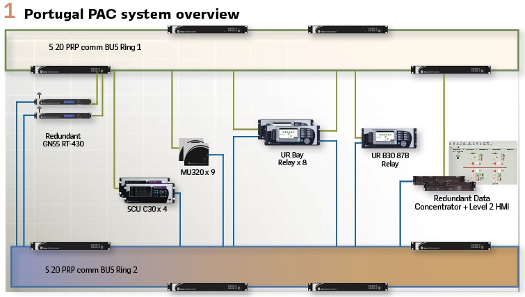
Level 0, hardwiring redundancy: Figure2 shows the typical hardwiring for a Portugal substation 115 kV bay. As mentioned before, each bay has two Merging Units working in a redundant mode. The substation has two 110 Vdc battery banks, so the Merging Units of the same bay use different power sources for the power supply and the digital inputs wetting. The necessary digital I/O signals for the operation and protection applications were connected to both Merging Units in an independent way and different CT cores were used, so the PAC system could keep working even in the case of one MU failure.
Communication wiring redundancy: Figure 4 shows the communication wiring. The communication wiring was designed so the connection to PRP bus ring 1 and PRP bus ring 2 of each IED had different cable routing. This was achieved by using different ODF and fiber optical cable for each bus ring.
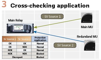
Process/Station Bus and synchronization redundancy: Figure 5 shows the shared bus (process/station bus) consisting of two PRP bus rings. Each bus ring is composed of four communication switches with redundant power supply supplied by different power sources. Thus, the PAC system could work normally even with a complete loss of a bus ring.
For time synchronization redundancy, the PAC system has two GNSS (Global Navigation Satellite system), each with GPS + GLONASS service and compliance with IEEE1588 v2 PTP and IEC 62439-3 PRP standards. Each GNSS is power supplied from different power sources.
Level 1, SV and GOOSE message redundancy: The information published by the redundant Merging Units of each bay to the network is used by the redundant protection relays so both protection relays can maintain the protection and control applications running even with just one Merging Unit working. This was achieved by setting SV and GOOSE message redundancy.
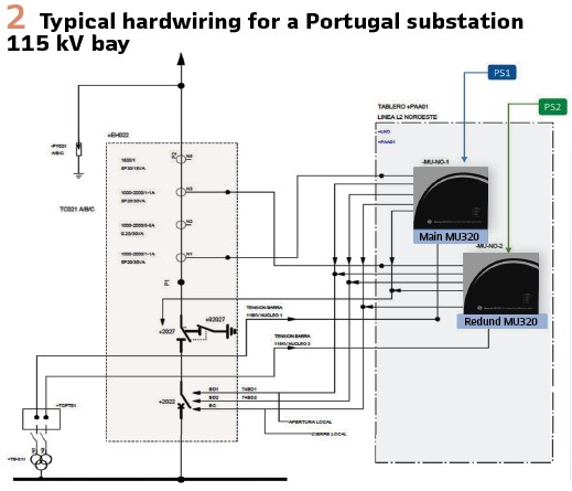
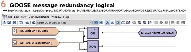
SV message redundancy: Figure3 shows how the Cross-checking application works. The protection relays are subscribed to the SV published by the main and redundant MU. One of the SV is set as the reference source and the other as the secondary source. The cross-checking application of the protection relay automatically decides to use the secondary source in case of bad quality of the reference SV (off-line or not synchronized). Thus, the control and protection applications could maintain running in case of a complete MU or SV quality failure.GOOSE message redundancy: Figure 6 shows the logic of the GOOSE message redundancy that was set using the programmable logic in the protection relays. The protection relays are subscribed to the GOOSE messages published by the main and redundant MU. The signals are connected to an OR logical gate, so in case of loose connection in the hardwired signals of MUs or loss of GOOSE messages from any of the MUs, both relays can have the correct information for control and protection application. The signals are also connected to an XOR logic gate to activate an alarm in case of discrepancy, so if the two signals are different, an alarm is activated.
Level 2 and 3, MMS integration redundancy: The redundant data concentrators receive the MMS reports from the two protection relays and uses some internal applications to manage the information in a redundant arrangement.
Redundant I/O: Figure 7 shows the logic of redundant I/O application setting in the data concentrators. The positions, commands and measurements are set in this application so the Level 2 (Local HMI) and Level 3 (ENEL Codensa Control Center SCADA) could supervise and control the substation even in case of a communication problem with one of the protection relays. The data concentrator can automatically or manually switch to the redundant signal in case of a reference signal failure.
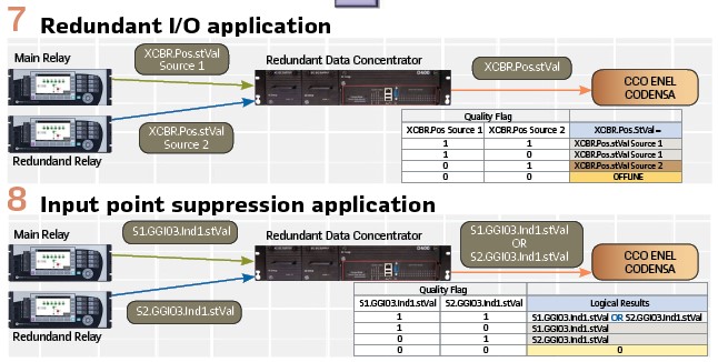
Programmable Calculator and Input Point suppression: Figure8 shows the logic of Input Point Suppression application setting in the data concentrators. ENEL Codensa Control Center SCADA has as a standard to receive some alarms as grouped. So, the programmable calculator application groups these alarms using an OR logical gate. When one or more of the signals conforming this grouped alarm goes offline, the logical result also goes offline regardless of the quality of the rest of the alarms. For that case the Input point suppression application, suppress this offline signal from the logical grouped, so the SCADA could be alerted in case another alarm is activated while another is offline.
Description of Results
Reliability Analysis
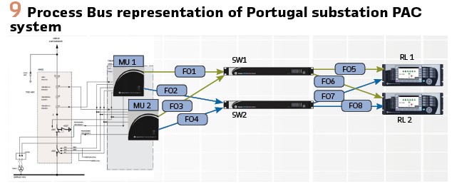
Process Bus Reliability: Figure 9 shows the Process Bus representation for each bay for reliability calculation purposes. The Process Bus Reliability for each bay of the Portugal substation system is calculated using the FTA method [2] as follow:
RSIST = [1 – [1 – [[1 – ((1 – RFO1) *(1 – RFO3))] *[1 – ((1 – RFO5) *(1 – RFO7))] *RSW1]] *
[1 – [[1 – ((1 – RFO2) * (1 – RFO4))] *[1 – ((1 – RFO6) *(1 – RFO8))] *RSW2]]] * [1 – [(1 – RMU1) * (1 – RMU2)]] * [1 – [(1 – RRL1) *(1 – RRL2)]] * [1 – [(1 – RFO1) *(1 – RFO2) *(1 – RMU2)]] *[1 – [(1 – RFO3) *(1 – RFO4) *(1 – RMU1)]]Where, RSIST, RMU1, RMU2, RFO1, RF02, RF03, RF04, RFO5, RF06, RSW1, RSW2, RRL1, and RRL2 are the reliability level of the protection system, merging units 1 and 2, optical fibers 1, 2, 3, 4, 5 and 6, switches 1 and 2, and protective relay 1 and 2, respectively.
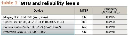
Table 1 shows the reliability level of the devices installed in the PAC System of Portugal substation.
Applying this reliability level to the formula, the reliability for the process bus of each bay of Portugal Substation is:
RSIST = 99.9930%
To achieve this level of reliability, it has to take into consideration that all of the following without exception has to be considered in the design of the PAC system:
- Two Merging Units, two protection relays, Ethernet redundancy
- Level 0 hardwiring redundancy, so both Merging Units have the same valuable information hardwired. It means all the positions, interlocking alarms, currents and voltage circuits
- Different ODF, optical fibers and fiber routes for each bus ring PRP1 and PRP2
- Process Bus PRP redundancy
- Cross-checking application for the protection relays to automatically switch the voltage and current source in case of a SV failure from any of the Merging Units and maintain the protection applications running
- GOOSE message redundancy, for the protection relays to keep running the 50BF and interlocking logic with reliability in case of loose connection in the hardwired signals of MUs or loss of GOOSE messages from any of the MUs
If any of the above is not considered in the design of the PAC system, the reliability level decreases. For example, if the PAC system has the hardwiring redundancy in the Merging Units but does not use the Cross-checking application or the GOOSE message redundancy, then the Process Bus could be represented for two parallel systems using one Merging Unit, Ethernet redundancy and one protection relay. The reliability for this Process Bus results in 99.989%.
The same way if it is not used hardwiring redundancy or PRP redundancy. A typical HSR system could result in about 99,11% to 99,30%.
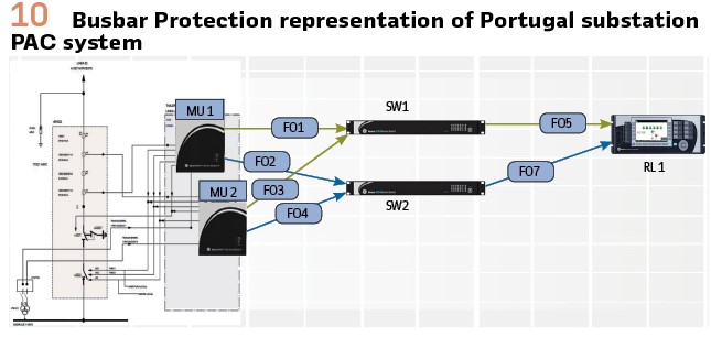
Busbar Protection Reliability: The Busbar protection relay in Portugal Substation is simple without redundancy but it is subscribed to the SV and GOOSE messages using the cross-checking application and GOOSE redundancy. Figure 10 shows the Process Bus representation for busbar protection for reliability calculation purposes.
The Busbar Protection reliability of Portugal substation is calculated using the FTA method:
RBBP = 99.7511%
Shared Bus Performance Test: The performance test of the shared bus (process bus and station bus) confirmed the expected results.
1. Blackout test, turning off all the IEDs of the system and turning on again. It is considered that the system is totally recovered when there are not failures alarms of SV, GOOSE, PTP or MMS messages active in any IED of the system (GNSS, Switches, Merging Units, Protection relays or Data Concentrator). The Portugal substation has obtained an average of about 7.5 minutes of total recovery (average after repeating three times the test).
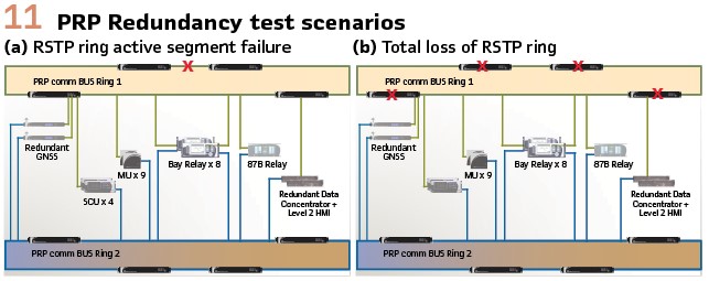
2. PRP redundancy test, simulating two possible failures on each RSTP ring of the communication bus as shown in Figure 11- an active segment failure of the RSTP ring and the total loss of the RSTP ring. In Portugal Substation there were no activation of failures alarms of SV, GOOSE, PTP or MMS messages in any IED of the system. That was the expected result since the recovery for a PRP system is 0 ms.
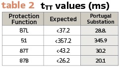
Protection applications performance: The response time of the protection application was measured by injecting a fault secondary current directly to each Merging Unit and receiving the output trip contact from the same Merging Unit. During the test it was generated eight bursts of GOOSE messages every ten seconds to simulate the worst condition of traffic in the network. Table 2 shows the Total Trip Time (tTT) measured in Portugal substation for the different protection functions, taken from bays test and compared with the expected tTT calculated.
Local HMI level 2 and SCADA level 3 applications performance: The Portugal substation has four level of Control. There the control from Level 2 (Local substation Data Concentrator HMI) and Level 3 (Enel Codensa Control Center) were tested and measured the time between a command and a change of state received in the mentioned Levels.
A Circuit Breaker Open/Close command cycle takes about 250 ms in Level 2 and about 320 ms in Level 3, and for a Tap Raise/Lower command cycle takes about 3500 ms in Level 2 and about 3900 ms in Level 3.
Conclusions:
The Portugal substation Process Bus has a calculated reliability level of 99.9930%. It was achieved by designing the redundancy in all the levels of control and using tools as Cross-checking and GOOSE redundancy logic.
The Busbar protection system of Portugal substation has a reliability level of 99.7511% since it is a single protection relay even when the Cross-checking and GOOSE redundancy logic is present in the system. ENEL Codensa is planning for new substation projects a redundant busbar protection relay to achieve the 99.9930% of reliability.
The reliability level calculation in Portugal substation shows that the reliability level of a PAC system depends on the design of the redundancy in all the levels and the capacity of redundancy settings in the IEDs that conforms the system.
The shared bus performance, protection application performance, and level 2 and 3 applications performance test show that the applications and logical settings implemented in the system do not affect the performance of the Portugal Substation PAC system.
The use of redundant application in level 2 and 3 as Redundant I/O and Input Point suppression permits that ENEL Codensa Control Center maintain and take advantage of the redundant PAC system since the smart objects in the substation diagrams screens normally has the capability to be linked just to one IED and signal (main protection relay). In case the main protection relay goes offline, the SCADA system loss supervision and control of the bay, so they have to prepare a second screen and manually open or replace the usual screen to continue operate.
This is not the case with Portugal substation system since in case of a signal or total main relay failure, the Data Concentrator automatically replace the offline signal(s) with the same from redundant relay.
This includes control, supervision and measurement points. So, the operator in the ENEL Codensa Control Center receives the alarm of main protection failure but can continue supervise and control the bay without the necessity to manually switch to another screen.
Biographies:

Andres Rodriguez was born in Bogota, Colombia. He has an electronic engineering degree from the Santo Tomas University, Colombia. He has sixteen years of experience in projects of the electrical sector. He is currently an expert professional of the Technical Planning & Solutions Optimization department in ENEL Colombia.

Carlos Polanco was born in Colombia. He has an electrical engineering degree from the La Salle University of Engineering, Bogota. He has twenty-three years of experience in Control and Protection system. He is currently expert professional of the Network System Department in Enel-Codensa, Colombia.

Ivan Otarola was born in Lima, Peru. He has an electrical engineering degree from the National University of Engineering, Peru. He has seventeen years of experience in Automation and SCADA system commissioning and nine years of experience in PAC system commissioning. He is currently the Manager of the Engineering and Service department in Soluciones Teleinformaticas y Control S.A. (SOLTEC), VAR of GE in Peru.

Julder Uzcategui was born in Barinas, Venezuela. He has an electronic engineering degree from the Experimental National University, Venezuela. He has twenty years of experience in PAC system commissioning. He is currently a Commissioning Engineer in the Engineering and Service department in Soluciones Teleinformaticas y Control S.A. (SOLTEC), VAR of GE in Peru.