by Walter Schossig, Germany, and Thomas Schossig, OMICRON electronics GmbH, Austria
The first part of this article shall cover the first half of the 1990s. It was a decade where protection as well as protection testing changed dramatically. To indicate the changes a publication of the IEEE Power System Relaying Committee, published in 1994, shall be cited. Based on a survey among 125 utilities, it compared the relay test intervals for electromechanical and non-electromechanical relays used in transmission, distribution, main generator, auxiliary bus, cogeneration, and large industrial substations.
Over the 20-year interval, 1971 to 1991, one can see a shift toward longer test intervals. For example, transmission electromechanical relays were checked every year by 63% of the utilities responding in 1971, compared to only 13% in 1991. These same relays in the 1971 survey were checked every 2 years by 15% of the respondents, and this had grown to 46% of the respondents in the 1991 survey.
Also, in the reunited Germany the working group “Relay and protection technology” at VDEW defined the requirements for a new protection test set. The test equipment shall be robust and easy to transport for instance in cars. The weight should not exceed 20 kg and allow manual as well automatic testing. It was the goal to have a unique data format for relay as well as test set vendors.
With the newly introduced digital technology with integrated hardware and software modules. Self-supervision allows to detect failures, devices with issues shall be taken out of service.
The self-supervision affects internal components as well as measurement circuits. The voltage 3Uo can be compared for instance as measured vs. calculated value. At the beginning there was a discussion, if all this makes routine testing obsolete. But it was obvious that also built in supervision could not deliver 100% safety, a risk for failures remains. For instance, binary inputs and outputs have been not included. Nevertheless, with the digital technology semi-automatic stationary test sets as used in the 1980s became obsolete.
So, the VDEW recommended in cooperation with the relay vendors to extend the testing period to 4 years. Within this period every 2 years a short function test was recommended (parameters, measurement values, binary inputs and functional test). Every 4 years a full test with primary values should be performed. In addition, batteries as well as electrolytic capacitor should be replaced.
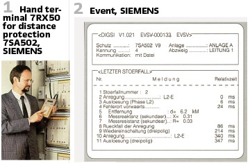
Digital relays are multifunctional and allow to store information. Setup via personal computers was introduced. Software allowed to set parameters, read disturbances, store, and print them out. The communication between PC and relay was serial (V24), with standardized transmission speed of 9600Bd or 19200 Bd. Another possibility for the setup remains the terminal (Figure 1).
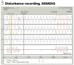
The software was called DIGSI (V1) already at this time. It allowed to show lists of events (Figure 2) and disturbances (Figure 3).
The first release of DIGSI for the digital distance protection 7SA500 was released in 1987 already. V2 for MS-DOS operating system followed in 1991, V3.3 supported.
Windows 3.x, Windows 95, Win. NT 4.0 and OS/2 Warp. In 1999 V4.0 supported Windows 98.
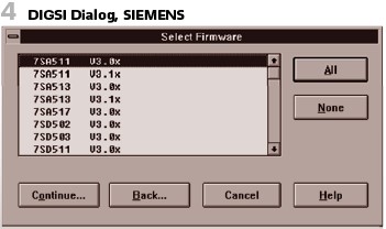
It is interesting to note, that DIGSI (SIEMENS item 7XS500) was delivered as a single floppy disk 3.5” (1.44 MB). Figure 4 shows the select firmware dialog box.
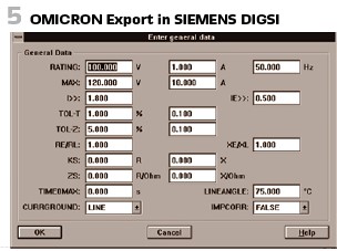
Also, testing was already supported. The partner of SIEMENS in this respect was OMICRON. DIGSI could export the data in the OMICRON format to support the use of the OMICRON’s test unit CMC 56 (SIEMENS item number 7VP15). Settings could be exported (Figure 5).

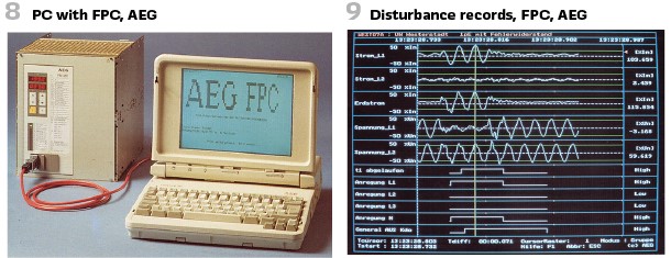
Another German vendor for protection devices was AEG. They introduced the setup tool for the protection of the integrated series for protection, automation, and control “ILS” in 1994 and called it “FPC”. Operating system was MS-DOS, the PC platform supported was IBM-AT compliant. All settings could be stored on floppy disks or hard drives. The connection to the relay was also a serial one (Figure 8).
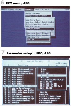
Figure 6 shows the typical DOS menus, in this case the German version.
Parameters could be edited as directly on the relay (Figure 7).
Also, disturbance records were available Figure 9.
As a part of the integrated system ILS also central setup and operation of the protection was possible. The central protection operation unit PSBE Figure 10 was capable to control 32 protection devices with ILSA-interface. Utilizing FPC software, dial-in modems or connected directly parameters could be set and disturbance records could be read. PSBE could also serve as a time master utilizing DCF77.
Additionally, the central protection data unit PZSE allowed the recording of all spontaneous messages, measurement values and to archive them.
Up to 127 protection devices could be connected. To collect the data and disturbance records IEC 870-5-103 protocol was used already, today known as IEC 60870-5-103.
It was 1991, when ABB released line protection REL316. It came with an own PC software for configuration, listing parameters, reading disturbances, listing events, and delivering diagnostics of the relay (Figure 11).
For the presentation of disturbance records an additional evaluation program was available (REVAL, MS Windows). For the GEM platform (Atari) there was the tool EVE. EVECOM (MS Windows again) was the tool for transferring disturbance records.
ABB produced an own test set, it was called XS92b (released in 1992). (Figure 12).


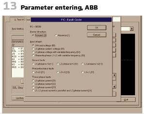
The computer based 3-phase test set has been designed for testing the functionality of all kinds protective relays (frequency, distance, directional or power relays) as well as being an aid for recording the operating and tripping characteristics of such relays. It contained a 16 bit microprocessor which permitted dynamic and static testing within wide ranges, whilst selecting current, voltage, phase-angle and impedance as parameters. The values of the settings could be checked by simply calling them up on a PC or onto a two-line liquid crystal display utilizing the hand terminal (option). The user could write testing sequences which correspond to his own particular circumstances and store them, or retrieve them, from the memory unit type YS92. Test programs for various protection relays. In the software values could be entered as shown in Figure 13.
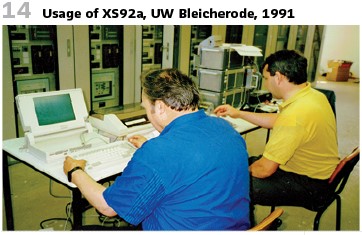
The author was involved in a project with ABB utilizing REL316 and RET 316. In the substation Bleicherode they realized the first project with digital protection in the new German counties after the reunion of Germany. It was put into operation on the 26th of July in 1991. Figure 14 shows the commissioning with the processor of the XS92b, the XS92a and with a COMPAQ laptop.
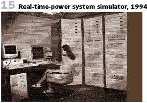
It was also in the 1990s, when Real-time digital simulators were used for protection relay testing. For instance, such a design has been built for Western Area Power Administration (WAPA) and delivered in 1994 (Figure 15).
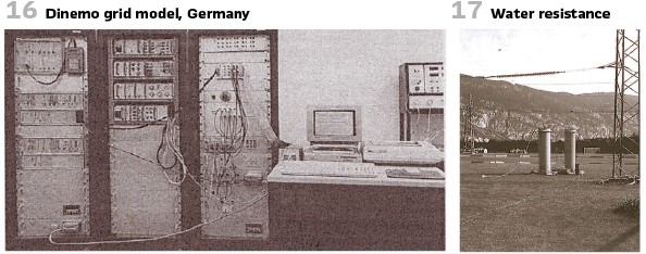
Another example for a digital grid model at this time was “Dinemo” at the institute for high voltage technology at the company Starkstromanlagenbau Berlin (Germany, Figure 16).
SIEMENS operated own real-time simulator “NETOMAC,” ABB built a lab for testing relays under real grid conditions in 1992.
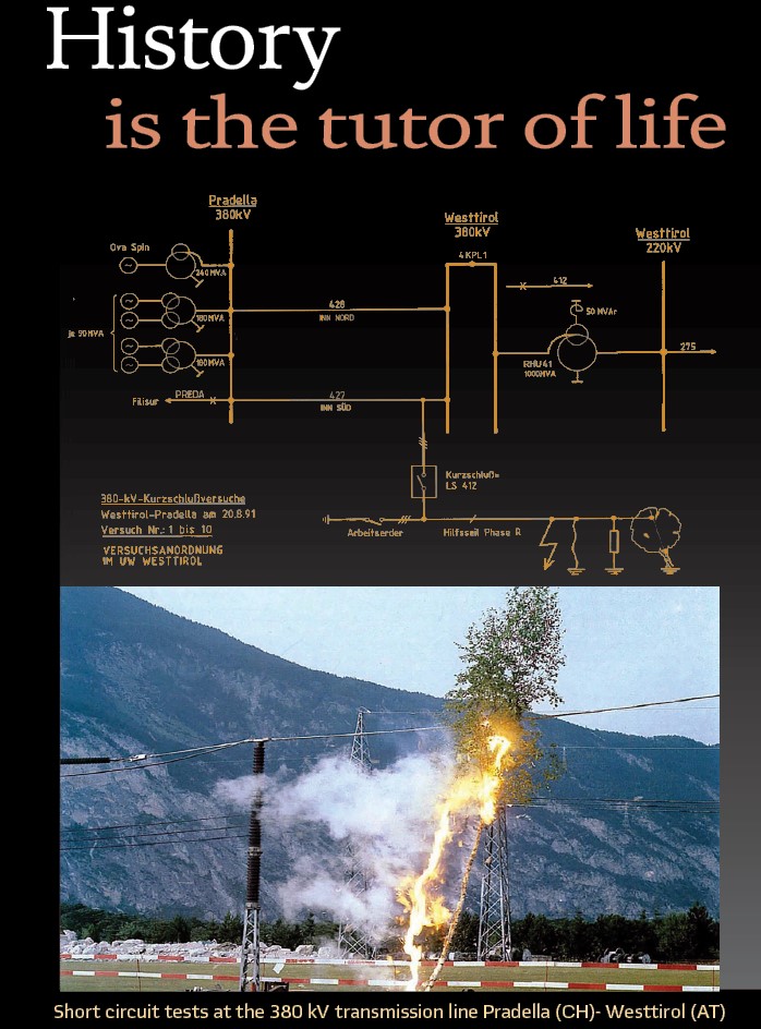
Another possibility to test protection under “real“conditions are of course short circuit tests in the field. An interesting example are the trials at a 380 kV transmission line between Westtirol (Austria) and Pradella (CH), performed on the 20th of August 1991 (see title page.) Relays used was ABB’s super-fast directional comparison protection LR91 and AEG’s digital distance protection PD551. The coupling line was put into operation for test at the end of 1990. Since there have been no experiences for those new relays at any utility in the UCPTE interconnected European grid, the TSOs Elektrizitätsgesellschaft Laufenburg, EGL and the Austrian Österreichische Verbundgesellschaft ÖVG, agreed on a two-years trial period and short-circuit experiments together. With AEG’s PD551 , ABB’s LR91 and the additional measurement element for high impedance earth faults RE93 several tests were performed.
- Single pol, metallic, full
- Single pol with arc
- Single pole with water resistance
- Single pole with tree
- Two-pole, isolated to earth
- Tree-pole with earthing disconnector
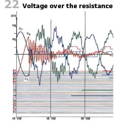
During the single pole earth short circuit fault, initiated by a copper wire 1.5 mm2 in substation Westtirol, the duration was 60 ms with a current of 1 kA . There was no damage to see on the wire inserted. Feeding from both sides the duration was 70ms (1.5 kA). No arc appeared, even after an unsuccessful auto reclose. Then the water resistance was inserted (130 Ω, Figure 17), duration of short circuit now: 100 ms at 1.3 kA. In case of single pole fault with tree (see title figure) it takes 4.5 s without a short circuit. The fault tree was 5 up to 7 A only. Repeating the experiment with the tree connected to lines it takes 2.5 s, then the arc starts. Duration of short circuit 80 ms at 2.1 kA. Figure 22 shows the voltage.
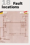
Other short circuit experiments were performed at the same time between Ukraine and Hungary. The 750-kV transmission line between Zapadno-Ukrainskaja and Albertirsa (Figure 18) had a length of 477 km. The designed transmission power was 2500 MVA. As protection relays again AEG’s PD551 was used, in addition SIEMENS 7SA502 and 7SA511, SIEMENS. The duration of the tests was 2 days. Alone at the Ukrainian side 1000 employees were busy to prepare and perform the six different tests. In addition, the vendors have been involved. SIEMENS net model was used for simulations when preparing the tests (Figure 19).
The results of the tests have been quite promising. The tolerance of the fault locations calculated was less than 5%, in case of fault with high currents even 2…3%. The operating times of the new relays were 30 ms.
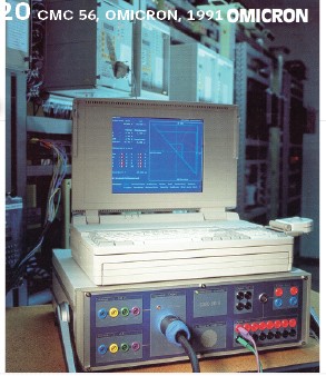
As mentioned already OMICRON was involved in the testing activities since 1990. The company, which started in the house of the founder Rainer Aberer in Hohenems, Austria was originally not in protection testing business but developed and marketed software for telecommunication applications. At a customer visit at an Austrian utility, they learned, that they are looking for a testing solution for the new digital relays and measurement transducers. Never been in touch with protection before a small team started the development and achieved first results very quickly. They called the device “CMC” which should stand for “calibrator for measurement converters” – based on the wrong translation of converters instead of transducers. The CMC 56 combined newest technology, visionary ideas, and new testing philosophy (Figure 20). Over the years the company became world leader in this industry.
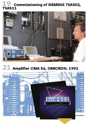
An easy-to-use software (MS-DOS as operating system) brought testing to a new level. The relay interface defined by OMICRON (RIO) became the standard for protection parameters as they could be used for testing as well. In 1992 the company was awarded with the local innovation price, in the same year with the CMA 56 (Figure 21) the first current amplifier was introduced.
In 1993 field trials at the Austrian Illwerke VKW took place, mainly testing the new software module for synchro check devices. The protection system for the 20-kV double busbar system was delivered by AEG.
The software modules in general shall be covered in a later paper more detailed.
It was also in the 1990s, when protection systems with Rogowski CTs were used for the first time. An example was a trial with busbar protection in a 1000-kV-UHV system in 1994.
This Busbar protection system was a multivendor and a separate feeder for the distribution system. This kind of system had been developed and operated in 1989. The difference to in-service systems was mainly that the UHV system used Rogowski CT and UHV Bus-bar protection used one slope characteristic. This kind of distributed system had been realized by proceeding two kinds of field test:
Environmental test: mounting a numerical relay in a cubicle outside.
Checking for interoperability: connecting with three manufacturers’ products.
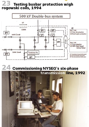
The general system configuration is shown in Figure 23. The overall Bus-bar protection element and the zone detect element are mounted in separate digital units. A line and/or transformer feeder is located near each GIS side. The current and voltage value is converted to digital data at each feeder terminal and is transmitting them to Unit 1 and Unit 2 relay calculation units via an optical LAN system. Trip signals also transfer from Unit 1 and Unit 2 to each feeder terminal. The physical topology is an optical star coupler method and network topology is a token ring method with IEEE802.4. It was also in 1994, when for the first time satellite-synchronized, end-to-end test outside the US was carried out at Zaporuzhye 750-kV-line in Ukraine. These dynamic tests were carried out using phasor values from load flow and fault calculations, and also with values from a recent troublesome fault.
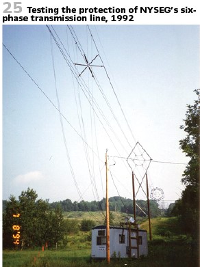
At the end we want to mention an amazing project. It was on 1992 when the editor of this magazine, Alex Apostolov and other experts worked on a project for a six-phase transmission line at NYSEG in the US (Figure 24).
Of course, protection and it’s testing was an important topic. Figure 25 shows Alex, testing the relays.
info@walter-schossig.de
www.walter-schossig.de
thomas.schossig@omicronenergy.com
Biographies:

Walter Schossig (VDE) was born in Arnsdorf (now Czech Republic) in 1941. He studied electrical engineering in Zittau (Germany) and joined a utility in the former Eastern Germany. After the German reunion the utility was renamed as TEAG, Thueringer Energie AG in Erfurt. There he received his master’s degree and worked as a protection engineer until his retirement. He was a member of many study groups and associations. He is an active member of the working group “Medium Voltage Relaying” at the German VDE. He is the author of several papers, guidelines and the book “Netzschutztechnik
[Power System Protection]”. He works on a chronicle about the history of electricity supply, with emphasis on protection and control.
Thomas Schossig (IEEE) received his master’s degree in electrical engineering at the Technical University of Ilmenau (Germany) in 1998. He worked as a project engineer for control systems and as a team leader for protective relaying at VA TECH SAT in Germany from 1998 until 2005.
In 2006 he joined OMICRON as a product manager for substation communication products. He is author of several papers and a member of standardization WGs.


