by Walter Schossig, Germany, and Thomas Schossig, OMICRON electronics GmbH, Austria
Looking into the 1980s we are starting in the GDR, Eastern Germany.
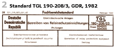
As a result of the comprehensive relay error statistics introduced in 1973 identified during commissioning and operation, regularity testing or fault clarification at the transmission and distribution network operators in the GDR, in 1982 the state prescribed standard TGL 190-208/03, February 1982, Operation of Relay Protection Devices. (See Figure 2).
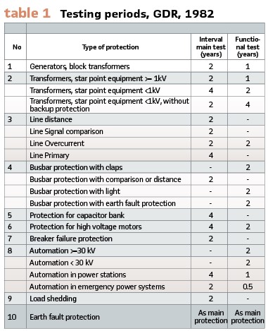
The testing period was doubled since the standard was in effect since 1962 (table 1).
It was possible to exceed the periods by 6 months. Additionally, in case of urgent operational needs, it was possible to eliminate some parts of the main test (for instance testing circuit breaker’s functionality) and catch up within 3 months. If the relay tripped selectively within this time or an auto-recloser took place, this was counted as a test of breaker’s functionality.
For main and backup protection systems for lines and busbars in the 220 kV and 380 kV it was allowed to double the interval if needed.
Also, BBC published a testing concept in 1981. The main parts (Figure 1) were:
- Continuous detection
- Testing the functionality
- Testing the accuracy
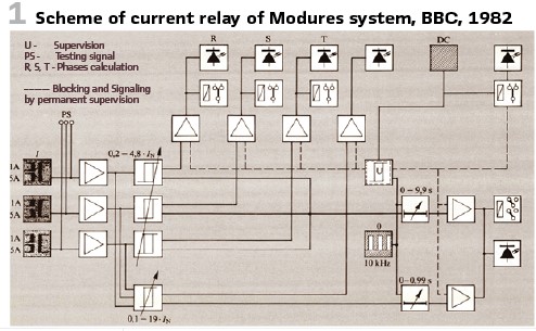
The continuous detection was used to detect malfunctions because of missing auxiliary power. So, the auxiliary power was supervised continuously. In case of loss of voltage, the relay was blocked, and a warning issued. BBC’s Modures systems came with stable crystal oscillators which were supervised as well. Additional logical checks, for instance with measurements for multiphase relays, improved the reliability.
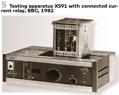
The functional check was the testing with a testing shot. The testing pulse superimposed the operating values and simulated a failure. This was essential for the static relays of this time, confirming the proper operation of measurement as well as protection. Relay’s availability was not much affected by the test. Due to low efforts, it was recommended to test every month at this time (Figure 4).
To test relay’s accuracy was mandatory. The test should include the measurement inputs and output contacts taking a lot of time. When relay’s functionality was tested regularly, the test of the accuracy was necessary once a year. Testing plugs increased the reliability. At this time portable testing devices instead of built-in testing possibilities were recommended. The devices were bought for the substations, in case of huge busbar protection systems built in testing devices were recommended by BBC. BBC’s testing device XV91 produced the testing signal and tripped the relay- even if the relay was in service. The “testing part” could choose among 7 measurement relays (this allowed for instance 2 3-pole and one single-pole relay to be tested. In a defined order, the tripping outputs were opened at first. After selection of the relay under test, in step number 3 the testing signal was connected to the relay. The relay indicates that it tripped. A secure, button allowed to trip the circuit breaker in addition. When changing to another feeder it was ensured that the tripping circuits did not remain open.
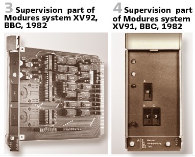
Figure 3 shows the supervision part XV92. For complex high voltage distance protection (as LZ96) also, the logics function should be supervised. All measurement values, their symmetry and logic signals could be supervised. In case of problems a warning was published, while severe problems blocked the protection.
To test Modures busbar protection INX5, the functional testing part XL91 was utilized. After manual trip, all feeder’s and busbar’s parts were tested. An external, as well as an internal fault was injected. A difference scheme supervises all the values during the test. In case of a fault, the test will be interrupted. This was necessary since the entire system was without proper protection at this time. The testing time was rather short. Less than 200 ms for the substation and 130 ms per feeder was possible.
The testing devices XS91 was intended to test mainly parts of the system with single measurement values. It allowed delivering a controlled current or a controlled voltage. An additional fixed voltage with phase shift of 0°, +60° or -120°/180° allowed the testing of medium voltage distance protection and directional relays. Figure 5.
For testing distance protection, the device QZW415 was in use. To test the accuracy 3 voltages and one current were available. The impedance characteristic of the relay could be tested with 2 angle settings.
The new XS92 allowed then to test every possible angle. Also, source impedance and time measurement were valuable features. Portable devices became the new choice for testing distance protection. Also, generator protection could be now tested.
The main functions of the distance relays LZ91 and LZ92 could be tested with test keys at relay’s front. Pushing them blocked the tripping output of the relay. Starting the startup elements allowed to test the timing elements and the stage indications.
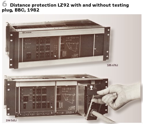
Also, the directional element could be tested in this manner. To test the characteristic, an impedance measurement suitcase was available. Connected via testing plugs, the current circuits were short circuited. This all happened automatically, the proper order of actions was guaranteed. Testing adapter XX91 and YX91 were connected. Additional measurement connectors allowed to connect multimeters. Currents were measured as proportional voltages. No disconnecting terminals needed to be opened, thus reducing the efforts. (Figure 6).
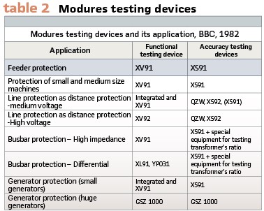
BBC’s testing devices for Modures and its application with technical data were covered in PACW December 2019 already. (Table 2).
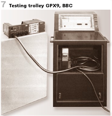
Especially for testing the modular system GSX9a BBC developed the testing trolley GPX9 (Figure 7).
For the evaluation of the testing results, manual methods as well as machine based with punched tape was common practice. Every computer, capable to read punched tape, could be used. Repeated tests could be stored now.
BBC’s static generator protection was GSX5e. It came by default with a “Manual testing rack” GSZ120 (Figure 8). Optional also the “fully automatic test rack” GSZ1000 (Figure 9) was available.
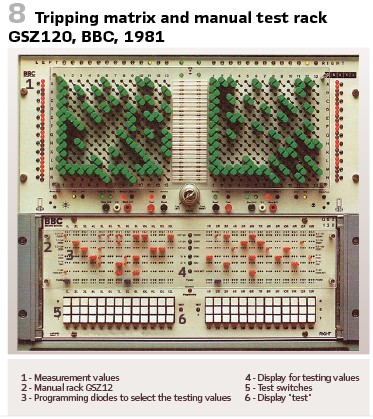
The testing system allowed the automatic testing of the protection as well as the wiring. Again, test switches at the front were used to inject testing values. The matrix and plugging diodes allowed testing of separate phases and protection functions. The currents (3 A or 15 A) as well as the voltages (20 V, 110 V, 220 V, and 100 V with 90° against the current) were predefined.
The automatic variant was compatible to the manual one and could be inserted even later. The protection functions were tested with test sequences. Startup values and the timing were predefined in setpoint storage (with tolerances). If the result was out of tolerance an alarm was indicated and recorded.
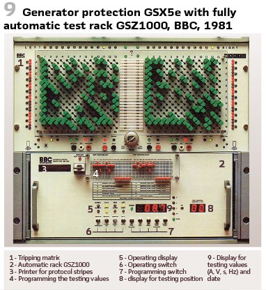
The bult-in printer printed the results on a paper role with date. Even an additional interface to send the results via telex or modem or the connection of a computer was available. To start the test a button could be pressed, or an external signal was connected. A built-in clock allowed the automatic test in a predefined period (8. 16, 24, up to 72 days) and with the part of the protection selected. Again, the test was performed when the relay was in operation. The trip could be disabled. The operating values were compensated during the test.
The testing values possible for this device:
- Current, variable automatically 0..20 A, 0..5A,0..1A
- Current, fix: 10 A, 2.5 A
- Voltage, variable automatically 0..220 V, 0..45 V
- Voltage fix: 110 V, 220 V, 100 V with 90° against the current
- Frequency, variable automatically 30 Hz. 80 Hz
Also, SIEMENS released in 1982 test equipment for overcurrent or tripping devices for currents of up to 2000 A (Figure 10).

Figure 10 shows the base unit with fine tuning and on the right hand-side the high current add-on. Both came with wheels for easy transport since the weight of 90 kg or 72 kg was high. It was a good idea to have two units, so the high-current unit could be based close to the measurement transformer but the base unit close to the relay. This also caused short connection cables to the high-current unit and reduced the voltage drops. Also, a 5000-A-device was available (Figure 11). This was much heavier: 290 kg and 315 kg. Figure 11 shows again on the left hand-side the current control unit, the right on is the high-current-unit.

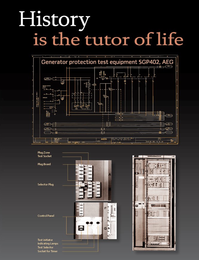
The German AEG released in 1986 the generator protection testing unit SGP402, with built in protection (title picture).
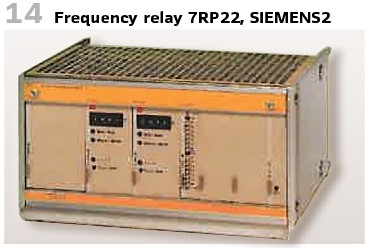
The documentation of SIEMENS frequency protection 7RP22 (Figure 14) came with a recommendation for commissioning:
- For the under-frequency measurement the setting of the relay should be a little bit above and below grid’s frequency. This allowed testing with grid’s voltage
- The tripping shall be tested during no-load proof of the generator. The revolution speed of the machine shall be according to a value of grid’s frequency
- The test with the primary testing equipment shall be repeated every 3 months, at least every 6 months
- A pick-up value check should be done routinely during machine overhauls. This check should include a check of the instrument transformer leads and the tripping circuits
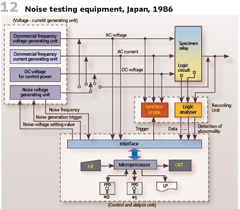
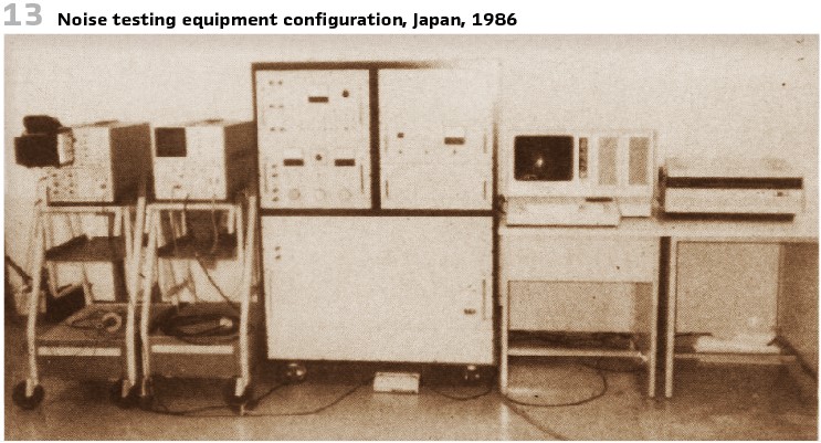
The Central Research Institute of Electric Power Industry in Tokyo, Japan, published a paper on noise testing equipment for existing protective relays in 1986. The goal was a view to making a precise analysis on operation of relays for noise. A new testing equipment has been developed and installed for trial, which was capable of generating a wide range of noise with frequencies from 1 kHz to 2 MHz A series of noise testing was performed with static relays. (See Figure 12 and Figure 13).
Also, ASEA in Sweden used the progress in electronics and computers for relay testing in that manner, that they develop simulators. With digital controlled analog simulators, they allowed grid’s and device studies. Results of a field test in the 735-kV grid compared with the results of simulation proved the quality of the new simulators. The RALDA protection was the fastest protection at this time (operating time less than 5 ms), even including static output relays and communication between both ends of the line. (Figure 15).
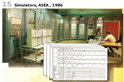
Grids with voltages between 100 kV and 1500 kV, with short circuit power of 50.000 MVA could be simulated. The digital controller communicated via IEEE 488 to the analog part. The computer was a HP 1000 F with 1 MB RAM. The control computer was HP 100 L with 512 kB RAM. It could store 24 analog and 64 digital signals. A hard disc with 200 MB, Floppy disk (1.2 MB), magnet tape, printer and plotter were connected as accessories. The software used the Jackson method and was written in PASCAL and Fortran 77.
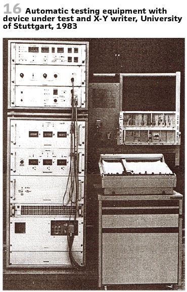
The German Utility Energie-Versorgung Schwaben (EVS) and the University of Stuttgart developed in 1983 a device for automated testing of distance protection. It came with X-Y writer. (Figure 16).
To be continued in the next issue.
info@walter-schossig.de www.walter-schossig.de
thomas.schossig@omicronenergy.com
Biographies:

Walter Schossig (VDE) was born in Arnsdorf (now Czech Republic) in 1941. He studied electrical engineering in Zittau (Germany) and joined a utility in the former Eastern Germany. After the German reunion the utility was renamed as TEAG, Thueringer Energie AG in Erfurt. There he received his master’s degree and worked as a protection engineer until his retirement. He was a member of many study groups and associations. He is an active member of the working group “Medium Voltage Relaying” at the German VDE. He is the author of several papers, guidelines and the book “Netzschutztechnik
[Power System Protection]”. He works on a chronicle about the history of electricity supply, with emphasis on protection and control.
Thomas Schossig (IEEE) received his master’s degree in electrical engineering at the Technical University of Ilmenau (Germany) in 1998. He worked as a project engineer for control systems and as a team leader for protective relaying at VA TECH SAT in Germany from 1998 until 2005.
In 2006 he joined OMICRON as a product manager for substation communication products. He is author of several papers and a member of standardization WGs.


