by Walter Schossig, Germany, and Thomas Schossig, OMICRON electronics GmbH, Austria

It was in 1986 when CIGRE Working Group 04 Study Committee 34 (Protection) published testing recommendations for the different types of relays, covering analog-statical protection devices. .
On 101 pages they covered Steady-State, Single-Source and Double-Source tests of distance, line, busbar, and transformer protection. The report was intended to provide guidance on the tests required to establish the characteristics and performance of power system protection relays and protective systems, leaving the issuing of a standard to IEC. The basic philosophy of this report was to propose functional type test programs by using generally accepted methods of testing and test conditions as much as possible.
Steady-state tests were intended to measure the operating characteristics of the measuring functions of the relay. For single-input measuring functions (as over-current) the operating and the resetting values are measured. For double-input measuring functions as impedance function, the operating characteristic depend on magnitude a phase angle of both energizing quantities.
Single-Source dynamic tests were intended to measure the operating times and dynamic accuracy or sensitivity of the relay whilst simulating basic types of faults on a single-source, three-phase power system.
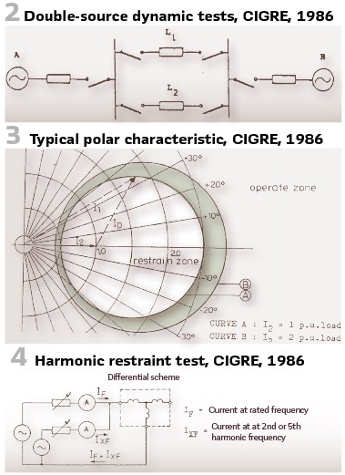
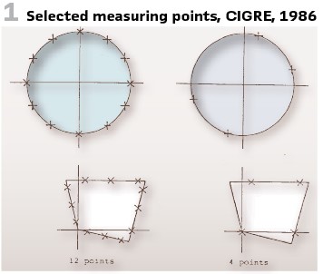
Double-Source dynamic tests were performed by simulating basic fault and fault clearance sequences on a double-source power system scheme (Figure 2). They were designed to establish the operating time and correct operation of the protection when simulating faults and faut clearance of the protected line (e.g., on line L1) and the non-operation of the protection when simulating faults and fault clearance sequences on an adjacent line (e.g. on line L2). Examples for functional tests of distance relays are shown in Figure 1, for transformer differential in Figure 3 and Figure 4.
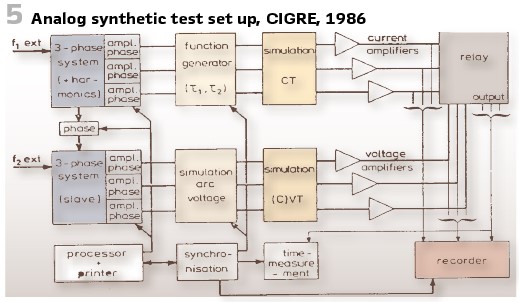
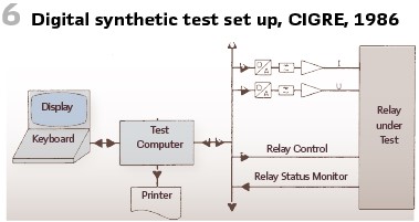
The publication “analog synthetisers” (Figure 5) describes how to perform steady-state measurements as well as digital ones for synthetic tests from digital computers with D/A outputs and amplifiers (Figure 6).
GEC ALSTHOM’s “Protective Relays Application Guide” was published in its third edition in June of 1987. The first edition of this book was published in 1966 and it is popular in the industry and is published by the different successors until today. It contained a lot on testing and testing devices, some of them to be mentioned here.
The CDG relay is still widely used today (Figure 8). It came with withdrawable features of relay case to simplify testing and maintenance of the device.
With the modern relays, printed circuit boards (PCB) became a part of the relay, tested already during production.
An entire chapter is covering testing and commissioning. The testing of protective schemes has always been a problem, because protective gear is solely concerned with fault conditions, and cannot therefore readily be tested under normal system operating conditions.
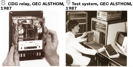
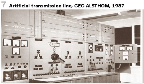
Factory and production tests are in the responsibility of the vendor and have been performed at test benches at this time (Figure 9). Figure 7 shows the artificial transmission line of the company. It provides an adjustable current or voltage, or both, at the relaying point, with control of the circuit time constant, duration of fault, point-on-wave at which the fault is applied, and the type of fault.
A push-button control panel was in use for medium current test plants (Figure on the top).
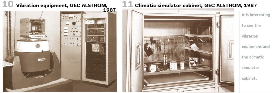

Also, interesting to see is the vibration equipment (Figure 10) and the climatic simulator cabinet (Figure 11).
On-site secondary injection was used. It was common practice to provide test blocks or test sockets in the relay circuits so that the connection can readily be made to the test equipment without disturbing the wiring (Figure 12, Figure 13).
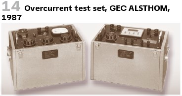
A typical test set for overcurrent relays is shown in Figure 14 and Figure 15. The current was controlled by means of tapped reactors in the primary circuit of the injection transformer. The injection transformer is provided with secondary tappings chosen to correspond with the current setting of the relay. This ensured that the relay impedance was small when reflected back into the primary circuit of the injection transformer, and reduced the harmonics in the test set current that were due to saturation of the magnetic circuit of the relay under test.
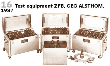
For distance protection portable test equipment type ZFB was available (Figure 16).
To test the stability of restricted earth fault relays, primary injection was used.
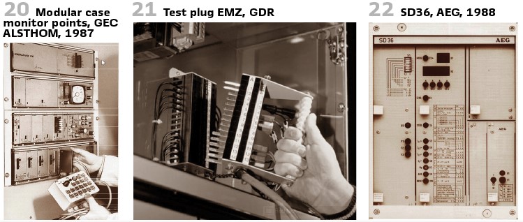
In the more complex transistorized protective schemes supplied in the modular test case shown in Figure 20, monitoring points on the front of equipment were essential for checking the various stages of the electronic circuits. This facilitated the rapid isolation of any faulty relay module, so that it could be replaced quickly.

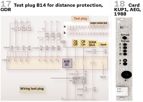
In Eastern Germany, the GDR, it was common practice and standardized to have test plugs in all substations and power stations for any protection applied. Also, the connection schemes as well as the terminals have been standardized.
Figure 21 shows the example for distance protection. Contact pins #9 -12 were longer than the others and interrupted the tripping of the circuit breaker as well as the position indication. In addition, contact pins #1a …4 a short circuited the CTs. Connections 1b …8b allowed now the injection of the testing values. On- and off pulse could be used via pins 9b and 11b. At pin #13b and #14b auxiliary voltage could be accessed. Later #13a and 14# were used to stop indications of digital protection (Figure 17).
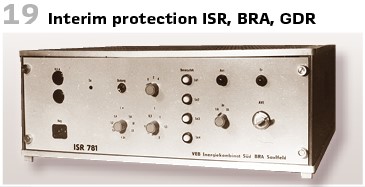
To make protection testing possible in live substations, the utilities in Eastern Germany developed an own “interim protection.” Produced in Saalfeld (Betrieb fur Rationalisierung und Automatisierung – BRA) it came with an overcurrent relay and could be connected to the test plug. Line’s protection settings have been taken over for overcurrent protection. In case of distance protection, the time was set as t2- this allowed limited selectivity (Figure 19).
At the same time in Western Germany AEG delivered as a part of the INTERMAS system a testing card KUP1 to test auto recloser (1988)- Figure 18.
It was designed to test 1- and 3-phase auto reclosers by pressing the test button. A 200-ms-pulse was injected, stimulating the protection startup and trip, starting the auto recloser.
AEG’s static distance protection relays SD36 have been available since 1985 (Figure 22).
To collect field experience, it was in operation during a period of thunderstorms to protect 220-kV-line. For 5 months there were 12 earth fault short circuits, and it started up once because of load current (the overcurrent startup value was chosen rather low.)
All measurement values and indications have been recorded during the trial period. Disconnectors have been in operation more than 100 times but there was no interference at all.
A protection startup could be simulated easily by pressing the buttons S5- S8. As long as the buttons were pressed , the relay sees a startup. According to the characteristic chosen, a trip signal is simulated via the button S9. The trip signal itself is blocked during the test. In case of operating currents of at least 10% the check of the direction was possible. When the impedance independent total time is reached, the LED in button S9 indicates the trip of the relay. Also, a tripping test was possible. There was a recommendation to test the relay 6 up to 12 months after the commissioning and every 3 years.
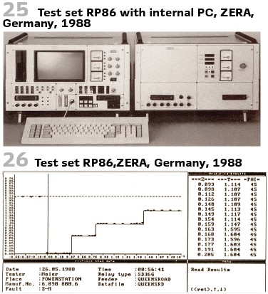
The German company ZERA presented in 1988 a computer-controlled testing device RP86 with external PC, or as a built-in variant (Figure 25) with 600-VA-current device.
The user could operate the device manually. U, I, Z, φand f could be entered utilizing keyboard and menu.
Alternatively, programed operation was possible. The program was loaded from floppy disk. After entering relay’s name, choosing the file with relay’s setting data, the program ran automatically. The results were written back into the settings file from which the settings were taken. The test results could now be printed out via printer or further processed to PC.
The third possibility was graphics mode. The operator could quickly obtain a survey of the set point and actual value curves of the tripping and the stepped characteristics. The curves were displayed on the monitor and could be printed out or saved. (Figure 26).
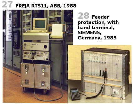
For the testing of numerical, static and electro-mechanical relays ABB presented the FREJA in 1988. The relay test system could be used for manual and automatic field testing. With three-phase current and three-phase voltage output is could be used for several applications. It was supplied complete with computer, display, device, keyboard, and printer. The accuracy was 0.5% of reading. Tests could be stored in device’s memory or printed out. Figure 27 shows the device.
Also, SIEMENS was working on testing solutions. Due to the huge amount of functions in the devices for static protection dedicated setting element for every function were not possible anymore. So, they came with a flexible terminal, like a pocket calculator (Figure 28.)
Via serial connection parameters could be set, and fault information could be read. On the LCD display of the device 7XR51 information could be read as clear text. Changing the settings of the protection demanded a special permission, reading was possible without this.
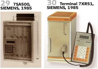
SIEMENS’ first digital distance relay was 7SA500. Also, here an additional terminal to be connected was available (Figure 29).
All settings could be entered utilizing the hand terminal 7XR50 or 7XR51 (Figure 30).
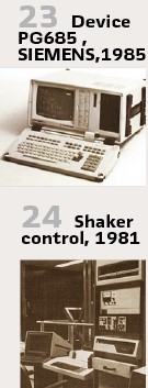
Another option was the portable setting device PG685 with menu operation (Figure 23).
It allowed setup, definition of the test cases, reading the values and visualization- with menu-driven handling. All values could be stored on floppy-disks, printers could be connected as well as plotters for printing disturbance records.
It was also in 1985 when BBC presented the programable testing device XS92a.
It contained a 16-bit-microprocessor. The alphanumerical hand terminal YB92 was used to enter the testing parameters. Amplitude and phase angle have been calculated automatically out of this. The calculated values were visualized on the 2-line LCD display at the terminal or to a monitor connected. With the serial V24 (RS232) connection a printer could be connected. The additional printed board YS92 delivered memory to store the test plans. YV92 was the board to connect an x-y-writer. The testing device allowed static and dynamic tests. All types of faults, considering source- and fault-impedances could be injected. All types of protection could be tested.
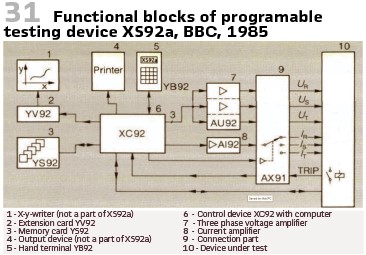
Figure 31 shows the functional blocks. Another type of testing was the test on seismic requirements for protective relays.
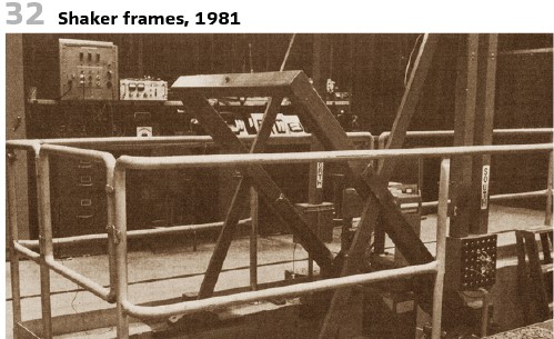
The importance of safe and reliable nuclear generating stations has been emphasized by the power industry in a number of ways. These include the development of standards which define requirements of performance for related equipment as well as provide guidance for test and maintenance of such equipment. “IEEE Standard for Qualifying Class lE Equipment for Nuclear Power Generating Stations”, IEEE Std. 323, identifies the earthquake as one of the environmental factors which equipment must withstand. IEEE Recommended Practices for Seismic Qualification of Class 1E Equipment for Nuclear Power Generating Stations”, IEEE Std. 344, further identifies the earthquake environment and describes methods for testing. Figure 24 shows the control of shakers used for this purpose; Figure 32 shows the frames.
The technical data of shaker and controls:
- Static force 2495 kg
- Dynamic force 1647 kg
- Reaction mass 36287 kg
- Vibration performance from 1 Hz = 1.2 g (acceleration) up to 40 Hz = 15.3 g
- Control PDP 11/04 processor with 28k memory and RX11 dual flexible disk
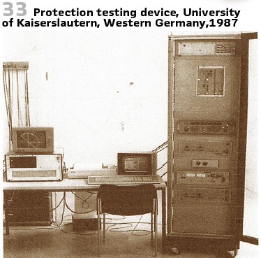
To test the impact of ideal testing signals the university of Kaiserslautern developed a testing device in 1987. (see Figure 33). Phenomena considered:
- Harmonics
- Fault resistances as arcs
- DC components in short circuit currents and voltages
- Electromechanical transients between generators
- Current transformer saturation
- Transient oscillation of capacitive voltage transformers
- Change of faults during short circuit
- Transformer inrush
info@walter-schossig.de www.walter-schossig.de
thomas.schossig@omicronenergy.com
Biographies:

Walter Schossig (VDE) was born in Arnsdorf (now Czech Republic) in 1941. He studied electrical engineering in Zittau (Germany) and joined a utility in the former Eastern Germany. After the German reunion the utility was renamed as TEAG, Thueringer Energie AG in Erfurt. There he received his master’s degree and worked as a protection engineer until his retirement. He was a member of many study groups and associations. He is an active member of the working group “Medium Voltage Relaying” at the German VDE. He is the author of several papers, guidelines and the book “Netzschutztechnik
[Power System Protection]”. He works on a chronicle about the history of electricity supply, with emphasis on protection and control.
Thomas Schossig (IEEE) received his master’s degree in electrical engineering at the Technical University of Ilmenau (Germany) in 1998. He worked as a project engineer for control systems and as a team leader for protective relaying at VA TECH SAT in Germany from 1998 until 2005.
In 2006 he joined OMICRON as a product manager for substation communication products. He is author of several papers and a member of standardization WGs.


