by Sakis Meliopoulos, Georgia Tech, USA
The IEC61850 standard evolved through many innovations and attempts to harness the benefits of these innovations. Pivotal was the development of the first computer relay in 1970 and the implementation via microprocessors in 1984. These innovations demonstrated that the logic of electromechanical relays can be duplicated and improved by computer algorithms and most importantly, communications among relays. The Utility Communication Architecture initiative was an attempt to develop an architecture that numerical protection and control devices would communicate and improve the protection of the system. UCA evolved into IEC61850 which promises an object-oriented approach to the overall protection and control (P&C) with interoperability among manufacturers. This has been an exciting goal.
The separation of the data acquisition system from the P&C functions via the introduction of merging units (MUs) was another step towards that goal. It enables the broadcasting of all measurements into a centralized depository to which multiple or all devices have access. This architecture coupled with the software approach to P&C defines the digitization of the power grid.
The possibilities are enormous, the sky is the limit towards addressing all the needs for protecting and controlling the system against power faults as well as protecting the system against cyber-attacks with many additional benefits such as providing a new paradigm for SCADA, situational awareness of the system, monitoring the health of the P&C of the system and others. In general, these are the objectives of the digitization of the power grid.
The IEC 61850 is pivotal in facilitating the digitization of the grid and achieving the goal of automating all the relevant functions.
Digitization of the Power Grid
The digitization of the power grid is considered a requirement of the smart grid. But what is it? Why we should do so and how to do it? The concept of the smart grid is based on the basic principle that knowledge of the operating conditions of the power grid enables the intelligent protection, control, operation and optimization of it via appropriate analytics. This implies that the smart grid can be 100% computer controlled. The digitized grid comprises a monitoring system that measures the vital signs of the system, voltages, currents, frequency, topology and other and provides this information in digital form to computers that can perform the above-mentioned intelligent functions.
There are many reasons why we do so: (a) automation, automation, automation, (b) to improve the protection, control and operation of the system and (c) address and provide reliable solutions to many known problems such as P&C mis-operation, reduce P&C complexity, reduce P&C cost, adjust to changing characteristics of the system as more and more inverter based resources are added to the system, address life cycle and upgrading issues.
The question of how we can do so has two components: (a) enabling technology and (b) integration of technology to achieve the goals. Numerical relays, PMUs, MUs, Fault Recorders (FR) and any other Intelligent Electronic device provide the technology. Integration is an ongoing process that will require a lot of innovative work to reach the goals. Digitization also introduces the need for time tagging each measurement with sufficient accuracy which is provided by GPS clocks. Communications standardization is necessary for streaming the information to computing devices where it can be used for the ultimate goal of operating the system. The full implementation of the digitization of the power grid will take time and achievement of the goals of the smart grid will take even longer. In between, many progressive utilities will get there much sooner.
Today’s Challenges: The technological developments of the last 100 plus years resulted in powerful but complex P&C schemes. Complexity rises by the need to coordinate all protection functions for the purpose of selectivity, and speed, i.e. isolating only the faulted component(s) and allowing the rest of the system to continue operation. While tools for performing relay coordination studies have improved dramatically, yet the inherent competing factors in relay coordination has substantially contributed to the unreliability of P&C; a substantial percentage of relay mis-operations are attributed to mis-coordination. Thus, reducing complexity will be an effective approach towards minimizing relay mis-operations.
Another challenge to the performance of P&C has been created from the introduction of inverter interfaced generation resources. Specifically, the majority of protection functions have been designed to detect faults and abnormalities in a system that is dominated by synchronous generators. This system is characterized with high fault currents and presence of substantial negative and zero sequence components. Legacy protection functions utilize these characteristics during faults to detect them, determine the direction of the fault and the location of the fault. An inverter dominated power system has different characteristics: reduced fault current levels, absence (or substantially reduced) of negative and zero sequence components. In addition, inverter systems have complex control loops that can interact among various inverters as well as with relay logic in ways that can be very complex. These interactions must be studied for the purpose of understanding the possible vulnerabilities. It is recognized that new protection approaches need to be developed to address these problems. One can ask, “how can we modify the protection functions to perform well in the new systems,” or “can we develop new protection approaches that will be immune to the new characteristics.”
In addition, we have a number of perennial problems. Hidden failures in P&C systems, i.e. AC wiring, DC wiring, etc. frequently result in relay mis-operations. Protection gaps, i.e. fault events that we do not have reliable ways to detect and protect against. Protection gaps include downed conductors in distribution systems, faults near the neutral of transformers, reactors, capacitor banks and others.
Another challenge is cyber-security as P&C systems are becoming computer and communications dependent. Cyber-vulnerabilities have been identified in today’s P&C systems.
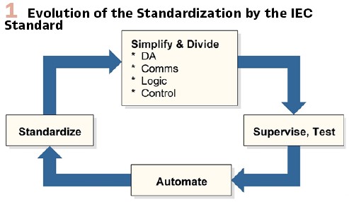
Addressing the Challenges: The present challenges can be effectively dealt with through the digitization of the grid and relevant technologies. These technologies allow the automation across all protection and operations of the smart grid. First, the digitization provides reliable technology to supply accurate data to all applications for the modern power system, including P&C. Second, reliable data enable effective performance of all applications. Therefore, the two important features are: (a) providing accurate and secure data, and (b) using the data to run the applications. IEC 61850 is critical in both, the implementation of the digitization technologies and the applications. Figure 1 illustrates the process by which IEC61850 addresses these two features. It provides standards for Data Acquisition (DA) via merging units and all the associated “glue” technologies, i.e. communications, controls and logic. It also addresses issues of supervision and testing. Automation of the applications provides feedback to the process to fine tune the standardization as showed in Figure 1. This process enables the evolution of the IEC61850 towards a mature technology. It is important to recognize that the MU technology, including switchgear control hardware provides a greater flexibility and the hardware platforms to better achieve the objectives of the IEC standard.
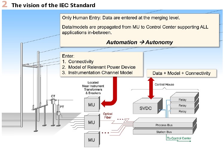
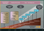
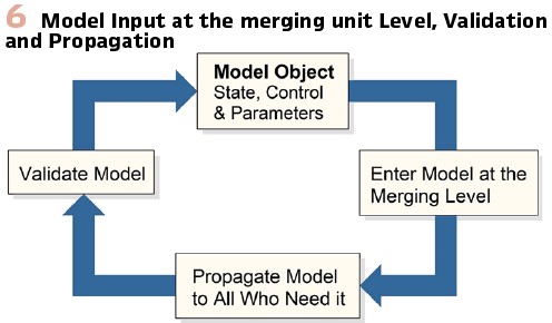
The ultimate goal is the automation of P&C and optimized grid operation. The promise of the IEC61850 is to provide the platform to achieve this goal. IEC61850 is based on the vision that all the applications will be object oriented, and they will be performed by computers with minimum or no need for human inputs. This vision can be realized with the concepts illustrated in Figure 2. Specifically, the physical system model can be defined at the merging unit level. The inputs consist of the power device models, their connectivity and the instrumentation channels (measurements) connected to MUs. Then this information together with the actual measurements consisting of analog and digital data will be transmitted to the process bus, forming the sample value data concentrator (SVDC) as shown in Figure 2, and be availablefor any conceivable application. Relays represent the logic applied to these data to take decision for P&C of the system. For data management, since logic may require phasor or sample value data, voltage and current data can be converted to phasors and stored at the station bus and an associated phasor data concentrator (PDC) as shown in Figure 2. Note this allows any application to access any amount of data, models and connectivity that are stored at the SVDC and the PDC. Data, models and connectivity can be also transmitted to the control center for system wide applications, such as voltage/VAR control, optimal power flow, security analysis and other.
To achieve this vision, all the information exchanges and applications must be objectified, so that computing devices can perform the analytics without any additional specifications. The IEC standard has the capability to address these issues, but it will require a lot of innovative work to reach these goals. To paraphrase the words of a past US president: Ask not what IEC61850 can do for you; Ask what you can do for IEC61850.
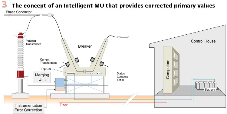
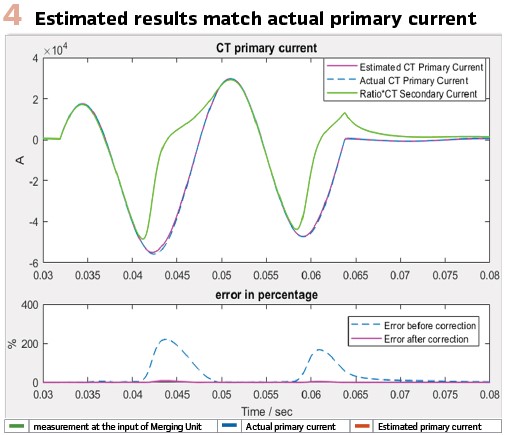
Data Accuracy, Validation and Correction: The objective is to deliver data – accurate and valid – to all, i.e. protective relays, controllers, control center, etc. Data exist at the merging Level and may have errors, small or large. One can adopt the norm that Merging Units Provide Primary Values and be provided the intelligence to perform Error Correction as it is illustrated in Figure 3. Error correction can be achieved by dynamic state estimation (DSE) methods that can model the instrumentation channel and formulate a dynamic state estimation problem which represents the primary quantity as a state of the DSE. The solution of this problem provides the best estimate of the primary quantity. An example of this process is illustrated in Figure 4 which shows a case of electric current measurement during a saturation event of the current transformer. Note that the best estimate of the primary current matches very well the actual primary current even during severe CT saturation. The correction is performed one sample at a time in real time, i.e. once a sample is measured, the DSE operates on this sample and past history of the measurements and provides the corrected value of the primary current. The same procedure applies to voltage measurements. This way the merging units provide streaming sample values simply delayed by the time required to execute the dynamic state estimation. This delay is much less than the sampling period.
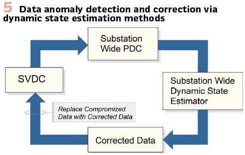
The standard should address all sources of error, such as hidden failures, model parameters errors, switch/breaker status errors and others. The dynamic state estimation provides a powerful tool to address this need as shown in Figures 5 and 6. Note that the sample value data concentrator feeds the substation wide phasor data concentrator by computing the phasors from the sample values. At the substation level, the data redundancy is very large, typically more than 2000%. The redundancy is defined as number of data (measurements) over the number of states describing the substation. Using the PDC data and the models and connectivity, the substation wide dynamic state estimation is constructed automatically. The DSE detects any data anomaly via the well-known chi-square test. In this case, hypothesis testing identifies the wrong data which then can be corrected by using the estimated real time model of the substation. Note that the corrected data can replace the wrong data in the SVDC to allow the system to operate with corrected data. It is important to emphasize that hypothesis testing can identify wrong data for a variety of reasons such as actual power faults, hidden failures in instrumentation, cyber-attacks to specific devices, and others.
Estimation Based Protection: System characteristics are changing due to inverter interfaced resources as discussed. The IEC standard, providing synchronized sample values is the perfect platform for new approaches to P&C that are immune to the characteristics of an inverter dominated power grid. The Estimation Based Protection (EBP) has been proposed as a reliable, fast, secure and immune to the effects of inverters P&C system.
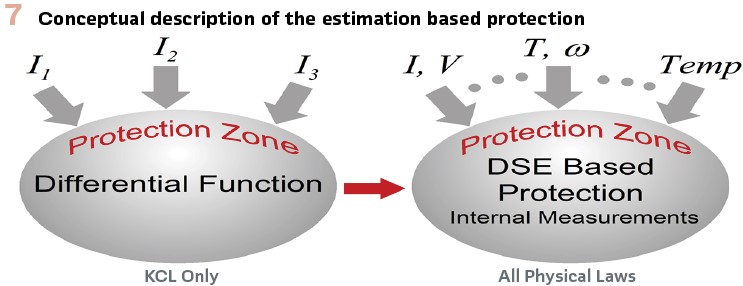
EBP has been inspired from the differential protection function as it is illustrated in Figure 7. In differential protection the electric currents at all terminals of a protection zone are measured and their weighted sum must be equal to zero (generalized Kirchoff’s current law). As long as the sum is near zero no action is taking. In EBP relays, all existing measurements in the protection zone are utilized and compared to the dynamic model of the protection zone via a dynamic state estimation procedure that quantifies how well the measurements satisfy the mathematical model. The EBP relay performance is independent of fault current levels and direction and other protection functions, i.e. it does not need to be coordinated with any other protection functions. Because of these properties the EBP relay provides full protection (against all abnormal and intolerable conditions) to any protection zone. It requires a high-fidelity model of the protection zone which needs to be entered, tested and validated at the time of commissioning. It requires simplified settings, such as maximum operating temperatures or other specific operating limits depending on the nature of the protection zone.
Model Objectification and Validation: A valid objectified model is fundamental for the automation of the power grid because the majority of applications are model based control. Validated objectified models are needed for the EBP relays. This can be achieved with the process shown in Figure 6: (a) models are entered at the merging level only as objects. (b) models propagate from the merging level to control center for use anywhere in-between. (c) model objects are validated at the EBP relay level by dynamic state estimation methods.
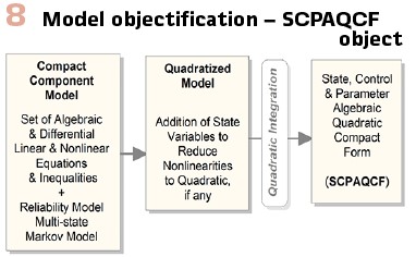
Model objectification has been a goal for many years. The development of the common information model is an attempt to describe models as objects. Yet, we have not achieved the goal of having a standard model object that will support all applications. We have developed a standard that can achieve this goal as shown in Figure 8. The model starts from first principles which lead to the detailed mathematical model of the physical power device as a set of algebraic and differential equations which may be linear or nonlinear. The model involves state variables, control variables and parameters. In order to develop the model as a structured object, we first quadratize the model by simply converting any nonlinear expression of degree higher than two to a nonlinear expression/equations with nonlinearities of degree less or equal to two, i.e. quadratic model. This is achieved by introduction of additional state variables. Subsequently, application of a numerical integration method the model is converted into an Algebraic Quadratic Companion Form in terms of state, control and parameter variables. This model is cast into a standard syntax, named SCPAQCF: State, Control and Parameter Algebraic Quadratic Companion Form. Quadratic integration is the preferred numerical integration method which fits well with the quadratic model.
One can realize that the IEC standard and the validated model objects can automate all functions in the power grid in the same way as we have discussed the automation of the P&C functions. Specifically, it can automate the system wide state estimation that will provide situational awareness to the operators. It can enable self-regulating by converting frequency control, voltage/VAR control and other regulating functions into autonomous procedures. The same can be done for all the management functions, such as multi-period optimization, operations planning and others, i.e. resulting in a self-management process.
Monitoring the Health of the P&C System: Failures in the P&C system adversely affect the reliability of the power grid. The IEC standard should be designed to provide continuous monitoring of the health of the P&C system and to self-heal the system in case of failures until the failures are repaired. This is the Big Gorilla that will make a dramatic improvement in the performance of P&C systems and the reliability of the power grid. The system of interest includes everything from the instrument transformers to the Control Center and all components in-between. This is of huge practical value. Hidden failures can manifest themselves in a variety of ways. They have caused major disturbances and blackouts.
Security: Security of P&C systems has taken two dimensions: integrity and cyber. Digitization means more computers, less human supervision. Security of cyber assets becomes a big issue, as we have seen the proliferation of cyber-attacks. It has been recognized that malicious players, if successful in gaining access to cyber assets, can inflict damages in multiple ways. The most feared cyber-attack is the weaponization of the P&C of a critical infrastructure.
Sleeper attacks can be designed to inflict maximum damage to the system. One such example is an attacker altering relay settings, i.e. CT ratios or PT ratios. This attack will manifest itself when a fault occurs which normally should result in the tripping of one circuit; instead, a number of circuits may be tripped because of the altered settings.
There are also soft cyber-attack targets, such as GPS Spoofing. Many relays are relying on synchronized measurements for proper functioning, such as line differential. GPS spoofing may result in multiple mis-operations of multiple relays causing major disturbances.
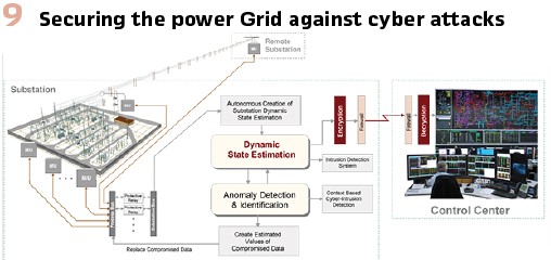
While we have identified many mechanisms of cyber-attacks, and substantial work has been done to harden systems against known threats, it is impossible to predict the ingenuity of the attackers. So the question becomes: What can be done to secure the P&C system from cyber-threats? There are multiple ways to mitigate the risk. First, cryptography is an ephemeral solution to cyber-security. Cryptography evolved with the computational technology. The basic design remains the same: encode information with keys that are not discoverable with present-day computational tools. IEC 61850 is able to provide end to end cryptography, MU to Control Center. Computational burden is manageable, and latencies can be minimal. Second, the cyber-infrastructure of the power grid moves information throughout the system that is related to the physical system. This provides a reference to detect any intrusions in the system. For example, the dynamic state estimation that has been described at the P&C level and at substation wide applications provides the operating conditions of the system. A system that continuously compares the data throughout the system to the operating conditions of the physical system can detect in real time any alteration of data (data attacks) or can determine whether a control is consistent with the present operating conditions (insertion of malicious controls). These are powerful techniques to detect intrusions in real time. The IEC standard is structured to provide the source (cyber-assets) of data and commands and thus to identify the attacked cyber-assets. This capability allows for quick containment and sanitization of cyber assets, as illustrated in Figure 9.
Conclusion: The P&C field has been experiencing a rapid development of relevant digital technologies that enable not only effective automation of these systems but also all other functions of the power grid. The digitization of the system requires standardization and imagination. Standardization to enable interoperability of hardware and software from multiple manufacturers; and imagination to create better automated solutions for P&C and also to create solutions to new challenges and old gaps in P&C systems; ensure the health of the P&C system; self-heal the system in case of failures; detect cyber-attacks; quarantine and disinfect compromised cyber-assets; automate system regulating functions; automate system management functions and many more. The IEC standard is critical to the digitization of the power grid and provides the platform for transforming imagination into reality.
Biography:

Sakis Meliopoulos received the M.E. and E.E. diploma from the National Technical University of Athens, Greece, in 1972; the M.S.E.E. and Ph.D. degrees from the Georgia Institute of Technology in 1974 and 1976, respectively. In 1976, he joined the Faculty of Electrical Engineering, Georgia Institute of Technology, where he is presently a Georgia Power Distinguished Professor. He is active in teaching and research in power system protection, control, operation and optimization. He authored more than 430 technical papers, four books, and holds three patents. Dr. Meliopoulos is the Chairman of the Georgia Tech Protective Relaying Conference.
.