by Michael Haecker and Christoph Bennauer, Schneider Electric, Germany
One of the main disadvantages of past communication standards have always been the limitations on the compatibility between devices from different vendors. This refers to the provision of sufficient system functionality by exchanging data in the right form and content. The IEC 61850 standards address this topic as a central requirement under the heading of “Interoperability.” A new tool and implementations for configuring the IEDs allows to ease the engineering process by a simple and efficient customized profiling within IEC 61850. A key benefit to users is the ability to customize the naming in any given installation allowing for a common, uniform naming convention across a site which is meaningful to that site.
When this is applied to all products with the same features it results in a common data naming and vocabulary regardless of manufacturer and promotes the goal of interoperability. Before a detailed description of this solution and the concept behind is given, a few notions shall be explained in the next section to get a common understanding.
Interoperability versus Interchangeability
Interoperability is the ability of two or more intelligent electronic devices from the same or from different manufacturers, to exchange information in such a way that a correct functional co-operation between information producer and information recipient is achieved.
To achieve this goal the standard provides the following key elements:
- Standardized class-oriented data modelling method to describe each possible data in its functional context which each tool and component in the system can understand and process (as long as both sides are using the same common data class)
- Standardized file format for the data model description and the device capabilities between tools of different manufacturers
- Standardized communication procedures called “services” to facilitate system wide interaction between components of different manufacturers to act as a complete system
- Standardized mapping on a network to use unique communication and hardware layers
- Test methods definition to verify an interoperable behavior of all system components during testing
Interchangeability is the possibility to replace a device supplied by one manufacturer with a device supplied by the same or another manufacturer, providing the same functionality with no impact on the rest of the system.
In terms of a communication protocol, compromises can be found to achieve an acceptable level of interchangeability without the devices providing the exact similar number and structure of data objects of their data models.
Conformance Testing
Conformance Testing was added to verify that the implementations of IEC 61850 into devices and tools of different manufacturers are conformant to this standard. Running a set of predefined test procedures, proof is given of the correct data modelling, implementation of services, provision of description files and documentation.
This testing only proves that there is no inconsistency between the data model, the description files and the documentation. The validation of which functional objects are modelled and how they are modelled is out of scope of conformance testing.
PN, FN versus fPN
As the standard offers a very flexible way of data modelling and allows a lot of room for interpretation, the data model of each IED from different manufacturers can diverge.
The freedom of defining the data model and the level of implementation allowed to manufacturers may result in an issue around interchangeability. In IEC 61850 the base data model of an IED as predefined by the manufacturer is referred-to as “Product Naming” (PN).
Product naming (PN) is the fixed or default data model of an IED reflecting the information content of the hierarchy/structure of functions inside an IED.
IEC 61850 also defines Functional Naming (FN), which is the reflection of the functional application view in the reference of information and is typically a primary equipment-oriented view.
To reach any level of interchangeability, it is required to align the data models in the IEDs to have the same naming and semantic of all data exchanged. IEDs that allow to modify and to customize parts of the whole data models, provide “Flexible Product Naming” functionality.
Flexible Product Naming (fPN) allows the data model of an IED to be modified up to a certain level to reflect the hierarchy/structure defined by the overall scheme. The user, in control of the naming details is able to arrive at installation specific, manufacturer independent IED data model conventions. The data model definitions can be applied to all IEDs supporting this facility, to modify their Product Naming into data models which are conformant and relevant to both the site and customer specific conventions. Based on this customized data model, all relevant data can be exchanged between the IED and its communication peers in an interoperable way.
Virtual versus Physical IED
A user specified IED data model which is not linked to an existing IED is called a Virtual IED. The used data objects are given independently of a real device and its function. It is typically linked to the FN view as the user bases all information to the application itself. A Virtual IED contains all required data for integration into the substation automation system.
A manufacturer specified IED data model, which is linked to the real functions of a real device and presented in PN view, is called a Physical IED.
fPN Concept
When using the method of modifying the IED data model, the Logical Node instances (representations of the functions) can be renamed by changing the logical node prefixes or suffixes or both of them. The logical node classes and the data object names cannot be changed. LDname, a concatenation of IEDname and LDinst, can be changed (Figure 1).
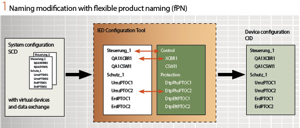
To reach interchangeability, not only the data model, but also the names of the elements for the data exchange, the communication service elements, data sets and report control blocks must be aligned.
Modelling Examples
Table 1 shows an example for an FN of a protection starting signal in bay “E2” of a “E110kV” substation called “Frankfurt,” provided as status information from a 2nd stage of a protection function called “Schutz1” with its sub-function overcurrent protection (“Umz”).
Table 2 shows an example for a PN of a protection starting signal modelled for a device “P433”, provided as status information from a 1st stage of the protection scope named “Protection” with its sub-function definite-time phase overcurrent protection (“DtpPhs”).
With the help of a tool a user can merge both data signal representations into an fPN model (see Table 3).
The tool will replace the main hierarchy elements as of IEDName, LDInst and the Prefix and Suffix of the LN class PTOC and to create a new IED data model.
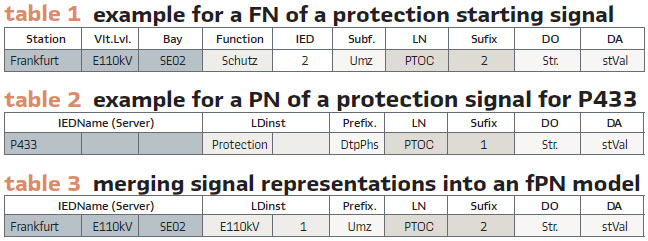
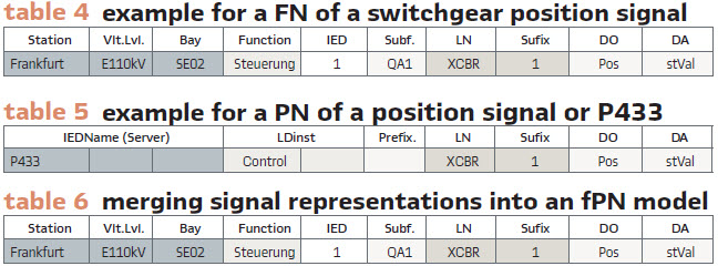
Table 4 shows an example for an FN of a switchgear position signal in bay “E2” of an “E110kV” substation called “Frankfurt,” provided as status information from a circuit breaker indicated as “QA1” according to IEC 81346 from a function called “Steuerung1.”
Table 5 shows an example for a PN of a position signal modelled for a device “P433,” provided as status information from a 1st circuit breaker node of the control scope named “Control” without an LN prefix.
With the help of the tool a user can merge both data signal representations into an fPN model (see Table 6).
fPN Editor Tool
The information concept of a user is specified in a System Specification Description (SSD). Part of this file are a number of Virtual IEDs, which each contain the structure and data model required for the user profile. To transform a Virtual IED specified by the user into a customized fPN IED model, a new data model editor feature was added to the Schneider Electric IED Configuration Tool (ICT). In this editor, the user will import the SSD to visualize in a tree view representation the Virtual IED model, to compare it with the Physical IED model in PN in a synoptical tree view. On basis of the two tree views, the user will add mapping links per drag and drop between objects of the Virtual IED and of the Physical IED in a simple way. The resulting fPN model is visualized in a third tree view. The user will map the specified objects only, which reduces the size of the resulting fPN model to a minimum complexity.
Figure 2 shows the three sections which visualize:
- The data model tree of the Virtual IED of the user (left hand side)
- The data model tree of Physical IED (right hand side)
- The mapped output data model (bottom section)
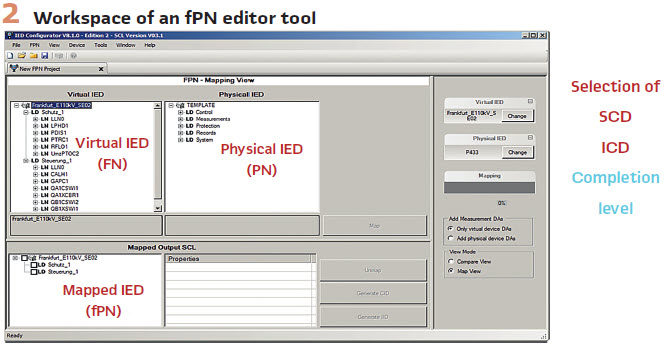
Opening a new fPN mapping project, the user defines the two data sources for doing the mapping, when selecting on one hand, an IED section in the project SSD/SCD for Virtual IED, and on the other hand, an ICD for physical IED. In the following example, a Virtual IED called “SE02″ is selected which contains the data for a protection device. An Easergy MiCOM P433 device model was identified to answer the requirements of the Virtual IED SE02.
As a matter of interest, the Virtual IED contains two LDs only, whereas the Physical IED has five LDs to structure the data model elements. The resulting fPN model will take over the structure of the Virtual IED as defined by the user in terms of LD and LN assignments, also each LN with its prefix and suffix. Therefore, the final data model will include only two LD.
Figure 3 shows the mapping procedure itself. After selecting an LN in the tree structure of the Virtual IED on the left-hand side by clicking on it, all data elements of the same LN class become visible on the right-hand side within the tree structure of the Physical IED window. The next step is to select the matching LN instance on the right-hand side. The actual mapping of this element is done by clicking on the “Mapping” button next to the Physical IED window. Boxes below the model trees of the Virtual IED and the Physical IED provide the IEC 61850 references and the description texts of the selected elements in both the Virtual IED and in the Physical IED. This information is helpful to identify the correct LN instance when having to choose among several LN instances of the same class. For that the user is supposed to have provided an application-oriented description in the SSD/SCD which he can compare with the function identifiers from the manufacturer when mapping the data.
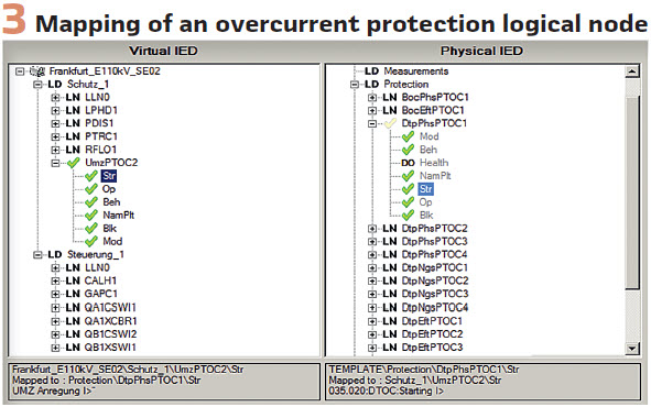
Ticks in green color confirm that the mapping of corresponding elements of the Virtual IED and of the Physical IED was made. Mapping can be done on logical node level and on data object level. LN level ticks in yellow indicate that the mapping of the subordinate elements is done only partially. If the Physical IED provides more data objects (DO) than those mapped to the Virtual IED, the tick on the Physical IED appears in yellow; the mapping of the required elements of the LN of the Virtual IED is done, though. The example shows a successful mapping for an overcurrent protection LN instance UmzPTOC2. Selected DOs are Beh, Str and Op which are mapped, visible at the Virtual IED and also in the output file tree structure.
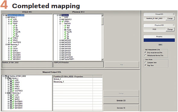
As soon as all logical nodes on the Virtual IED side are marked with green ticks, all mapping is done and the mapping progress bar on the right-hand side indicates a completion index of 100% (see Figure 4). The resulting device data model tree is visualized in the bottom section. Then, using buttons next to the output tree view an IED configuration file (Configured IED Description, CID) or a configuration export file (Instantiated IED Description, IID) can be generated.
Engineering Procedures
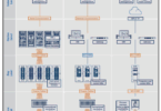
Basically, there are two procedures for engineering a system in Flexible Product Naming. The main difference between the two is the SCD: It can be manufacturer independent, i.e. built out of Virtual IEDs, or the SCD engineering can make use of fPN templates.
SCD of Virtual IEDs: For a manufacturer independent engineering, the system specification is transferred into a system configuration based on Virtual IEDs. The functional specifications of these Virtual IEDs are given user specific LN prefixes and suffixes. As the SCD is complete, it also includes the data exchanges of the Virtual IEDs. For the creation of an fPN configuration, the SCD is imported into the ICT and the steps described above are taken on a selected IED model. The resulting configuration is complete and can be loaded into the IED.
The said engineering steps have to be taken for all IEDs, since a configuration file is unique as shown in Figure 5.
Should there be the wish to keep an ‘as-built’ SCD, then it is necessary to export the fPN configurations for each IED as IIDs and to import them back into the System Configuration Tool (SCT) to generate the SCD.
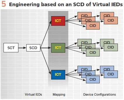
Engineering steps:
- Creation of an SCD with Virtual IEDs (functional specification) including data exchanges
- One-by-one import of a Virtual IED into the ICT
- Mapping of structure and data between Virtual IED and Physical IED data models
- Creation of project specific IED configurations
- Export of the CID files and download to the real IEDs
- For a full project documentation SCD: IID export and re-import of all IIDs into SCT
Working with fPN Templates: For projects with a big number of IEDs and for repetitive use in more projects it does make sense to modify the manufacturer ICDs into fPN modified ICDs before instantiating the IED models. Here, the system specification is made for typical bays only. In the SCT, the functional specification is given user specific LN prefixes and suffixes. The system specification is exported as an SSD (no instantiation yet).
For the creation of the fPN templates, the SSD is imported into the ICT and the steps for mapping described above are taken. At this step the real IED type and model is selected. The mapping export is still a template (ICD), but it includes the fPN definitions. Such fPN mapping is done for all the typical bays, providing new ICD files for the SCT.
With these fPN templates imported back into the SCT, the system engineering is made using the selected IED models for instantiation. Once the data exchanges of the IEDs are engineered, the project SCD is created. The SCD is imported into the ICT and the IED configurations (including the fPN definitions) can be generated without further mapping effort (see Figure 6).
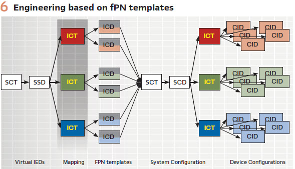
Engineering steps:
- Creation of an SSD with Virtual IED typicals (one template for each typical bay; functional specification, no data exchange)
- Import of each IED typical of the SSD into the ICT
- Mapping of structure and data between Virtual IED and Physical IED data models
- Export of the new fPN data models as ICD/IID files (IED templates)
- Import into the SCT, instantiate the templates to several IEDs, adding the data exchanges
- Creation of an SCD file with all instantiated IEDs
- Import one-by-one of all pre-configured IEDs into the ICT
- Export of the CID files and download to the real IEDs
Comparing the Procedures: Depending on the size of the installations and the expertise level of the engineering personnel, one of the two engineering procedures above is applicable.
The procedure using SCD with Virtual IEDs offers a minimum effort on the SCT and allows most of the actions to be engineered on ICT level, but it requires for each IED an individual fPN mapping. The SCD stays manufacturer independent.
Working with fPN templates on the other hand offers a high level of unification on the SCT level, doing fPN mapping one time per IED type and model. IED instantiation and the engineering of the data exchange is made on SCT level, resulting in a model specific SCD.
Conclusion
Generally, the communication standard IEC 61850 is intentionally designed as open and flexible to avoid unnecessary restrictions for future use and applications. The standard was not anticipated to achieve interchangeability beyond interoperability which was granted right from the start.
Where IEC 61850 to a certain degree allows manufacturers to decide on details of their implementations, this freedom permits the creation of similar, but not equal data models for the same applications. Engineering tailored to the individual device is needed and exchanging devices requests users to update configurations. To avoid this effort, applying fPN the user is able to design his system in such a way that it permits interchangeability by using unified data representations. It is the solution to arrive at harmonized data, system wide, fully in line with the system engineering process as of IEC 61850-6.
There is some effort to be spent in engineering the data model specifications and in creating the mappings, which pays back from a certain number of installations onwards which the user would equip with fPN data models.
Flexible product naming can provide a solution to come close to a user profile, meaning that the exchanged data representations become aligned and manufacturer independent.
Biographies
Michael Haecker studied Electrical Engineering with focus on Electrical Systems at the Darmstadt University of Applied Sciences, Germany. Since his entry into business life in 1987 with former AEG, followed by ALSTOM and AREVA T&D, he has been working in the field of substation automation. At present, he is Energy Automation Application Expert with Schneider Electric. Michael Haecker is member of several international working groups dealing with IEC 61850 and since 2015 Speaker of the German National Committee for IEC/TC 57. It is part of his business to define application-specific solutions in IEC 61850.
Christoph Bennauer studied Electrical Engineering with focus on Industrial Electronics at the University of Applied Sciences, Wiesbaden, Germany. He has been working for more than 30 years in the field of energy automation in Schneider Electric, AEG, ALSTOM und AREVA T&D. With professional expertise in R&D in particular, he leads the German R&D activities for more than 10 years. Five years ago, he took the position of global Application Expert with focus on railway protection and switchgear control.