by Walter Schossig, Germany, and Thomas Schossig, OMICRON electronics GmbH, Austria
Continuing the last article will investigate more earth fault compensation solutions. The paper will focus on Germany, at the end we will mention developments in the United States.
It was in 1921, when in 1921, Reithoffer was looking for a three-phase arrangement that would make the zero point connection superfluous. He clearly set himself the task of combining high idle noise dance with a zero reactance of different orders of magnitude in only one winding system and an electromagnetic circuit. These trains of thought led him to an asymmetrical zigzag circuit (Figure 1).
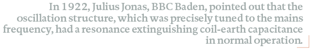
In 1922, Julius Jonas, BBC Baden, pointed out that the oscillation structure, which was precisely tuned to the mains frequency, had a resonance extinguishing coil-earth capacitance in normal operation. The presence of a slight voltage shift significantly increases this and suggests the dissonance of extinguishing coil. Also in this case, these trains of thought led him to an asymmetrical zigzag circuit (Figure 2).
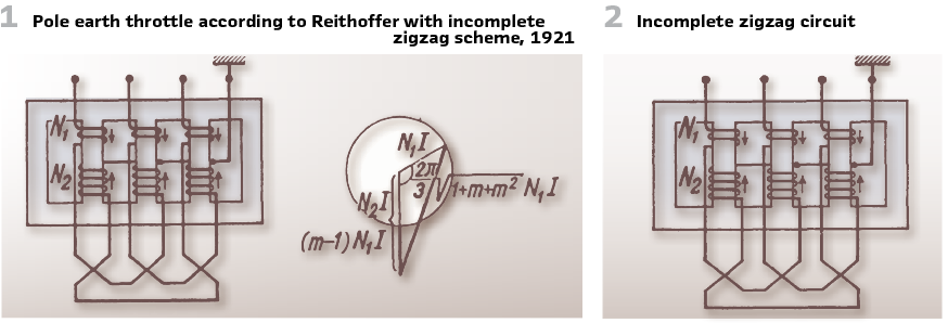
Figure 3 shows a dissonance extinguishing coil to protect 197 km of network length, for 50 kV and 905 kVA for 30 minutes.
As early as 1920, Schrottke, F. published a paper on “automatic detuning” in neutral compensator transformers (“Löschtransformator”). The most important feature of this transformer is the slight current control, which can be adapted to grid’s conditions. The inductance could be set. To avoid failures by manual operation, the device was equipped with a motor. It took 3 seconds to move from the highest to the lowest value. This is the maximum time for an earth fault arc to remain. (Figure 4). The municipality of Berlin (“Städtische Elektrizitätswerke Berlin”) decided to introduce Petersen coils in the 30 kV cable network in 1921. The reason was to make grid operation easier. The 30 kV stations Oberspree and Moabit were equipped with earth fault coils.
So, the entire cable grid could be fed by the coils. The grid was visualized on boards made of wood. Strings indicated the cables, plugs the switching devices. This is why the engineer quite easy could see which cables were connected to the coil. The length of the cables was visualized using the size of a small wooden board. This allowed the current to be adjusted accordingly. (Figure 5).
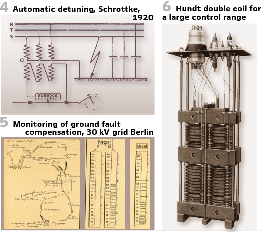
Sometimes a control range far exceeding the usual 1:2 is required. A control ratio of up to 1:4 can be achieved without significant saturation fluctuations using the double coil described by Hundt.
It (Figure 6) consists of two choke coils arranged one above the other and joined by a common yoke. Their windings can be used individually or in parallel. The common intermediate spar only carries a magnetic flux if the coils are operated individually or connected to taps where they do not require the same flux.

The coils are preferably made with different windings. For example, consider combining a coil for 7 A with one for 12 A. This allows for use at 7, 12, and 19 A without any taps and without saturation fluctuations. Extending the two partial windings by moderate amounts with intermediate taps, for example for 7, 6, 5 and for 12, 10, 8 A, yields 13 closely adjacent current levels: 5, 6, 7, 8, 10, 12, 13, 14, 15, 16, 17, 18 and 19 A.
Constructing a Hundt coil from three elements with 6, 9 and 12 A allows for the following current range without taps: 6, 9, 12, 15, 18, 21, 27 A, corresponding to a current ratio of 1:4.5.
The requirement for adjustable current consumption is a guiding principle for the design of earth fault coils. It is understandable that the inventors’ efforts were directed towards achieving continuous control without the aid of winding switching. Thus, it was proposed to adjust a ring-shaped filler piece with likewise wedge-shaped boundary surfaces in a wedge-shaped transverse gap of the leg and thereby influence the effective air gap (Elin, 1921).
All three-phase extinguishing devices have disadvantages compared to the inductive zero-point earthing of operating transformers that they constantly carry flux caused by the three-phase operating voltage and cause gauge losses year after year.
The single-phase ground fault coil for connection to the operating transformer at zero point asserts its precedence and prevailed.
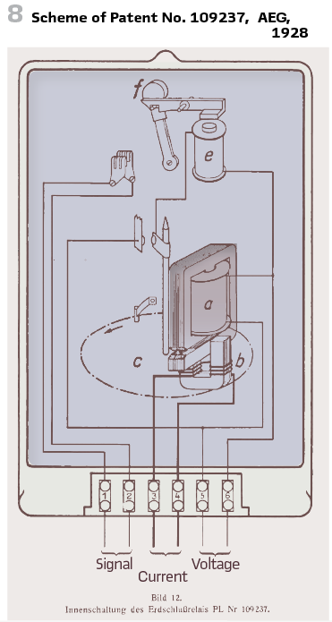
In 1922, v.d. Sterr, V&H, proposed the first power direction relays for selective earth fault detection. Here the current coil of the earth fault directional relay was applied to an asymmetric scheme. The voltage coil, as well as the timed voltage relay were supplied by the resulting phase-earth voltage. The scheme of those voltage coils can differ (Figure 7).
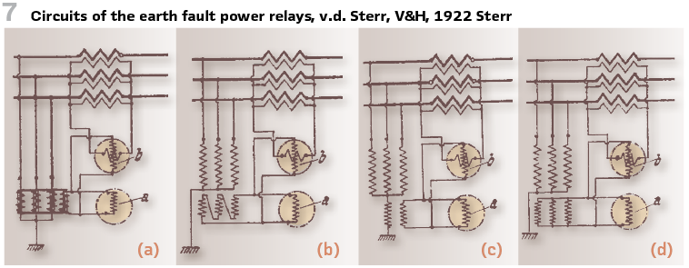
They can be connected to the fourth limb of an earthing coil (a). They can be connected to star-delta of a transformer with an open delta winding (b). Another option is to have the coil between transformer and earth (c). Option (d) is an asymmetric scheme at the secondary coil of the earthing reactance. Another option could be a connection via 3-phase series resistor.
In practice, the solutions according to c) as “open triangular winding” and d) additional voltage measurement winding in the Petersen coils have become established.
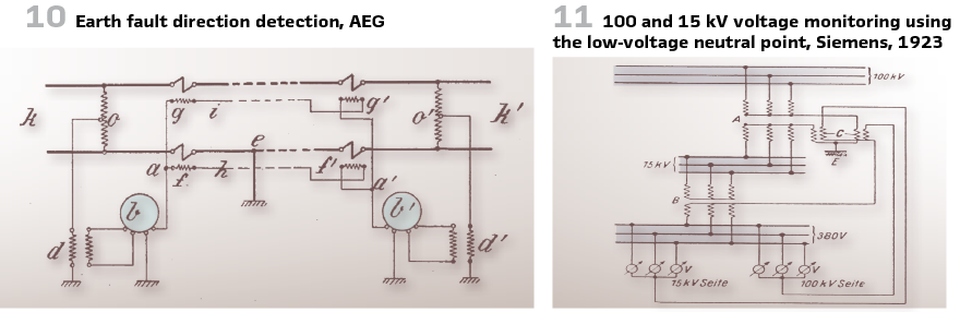
In 1923, in order to save costs and space by eliminating the need for voltage converters, Siemens proposed the use of the neutral point. A solution for the arrangement was to connect the neutral point with an intermediate voltage transformer with low isolation to monitor the voltage on the 100 and 15 kV side (Figure 11).
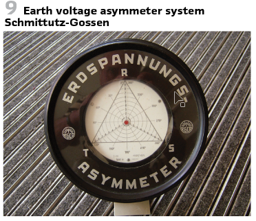
An earth voltage “asymmeter” by Schmittutz, Gossen, (Figure 9) shows the shift of the reticulated star point against the Earth’s potential very clearly. It has an equilateral triangle as a scale shield, which symbolizes the triangle of tension. A small round disc, which hovers above the scale sheet, represents the position of the earth’s potential. The rotary motion of 3 voltage measurement systems is transmitted to the small earth potential disk via cocoon threads. The position of the disk thus corresponds to the position of the earth’s potential in the stress triangle.
In the 1920s, the so-called wattmetric earth fault detection, in which the zero-power direction is determined from the product of the displacement voltage and zero current, became established for selective earth fault detection. The term “watt-metric” method refers to the evaluation of the power of the zero system.
While in the isolated network (in German Ohne Sternpunkterdung-OSPE without star point earthing) the capacitive earth fault current predominates, in the compensated grid (RESPE -Resonanzsternpunkterdung- resonance star point earthing) only the ohmic residual earth fault current is predominantly available.
Thus, in the isolated network, the sin Phi circuit with evaluation of the zero-power reactive power was used, and in the compensated network, the cos Phi circuit with evaluation of the active power was used.
The term “watt-metric” for both methods can be traced back to the fact that in the past, the reactive power in watts, e.g. in BkW.
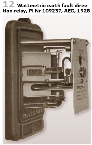
In 1924, for example, AEG manufactured the earth fault direction relays Pl No. 69046 and Pl No. 109227 in accordance with DRP 336210 (Figure 10) and the RMS and RE relays ASEA.
Figures 8 and 12 show the internal gearshift and the view with the Ferraris disc of the Pl No. 109237 from 1928, which has been used for a long time in meters.
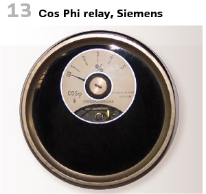
The cos Phi relay developed by Schleicher and Graz, Siemens, is shown in Figure 13.
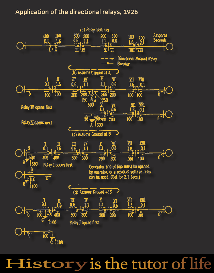
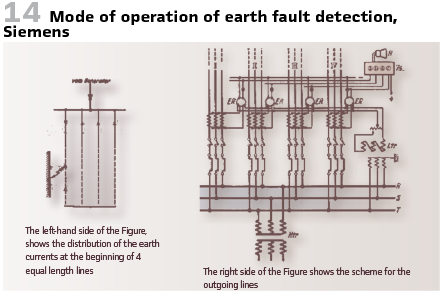
The mode of action can be seen in Figure 14. On the left-hand side, we see the distribution of the earth currents at the beginning of 4 equal length lines. On the right is the scheme for the outgoing lines.
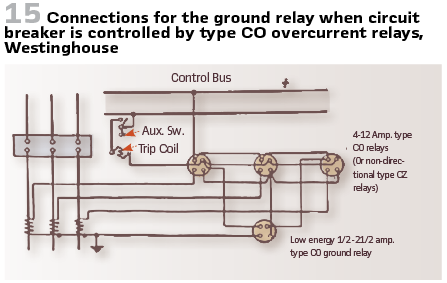
At the end we are looking at what happened in the US. In older issues we already looked into the book SILENT SENTINELS-Protective Relays for A-C and D-C Systems by Westinghouse, published in 1924. One chapter is covering the methods of clearing ground faults.
For solidly and low-Resistance-grounded neutral systems, protection with overcurrent relay (“CO”) and directional relays (“CR”) was recommended. Selective differential relays (“CD”) should be added to not require additional relay for wire-to-ground faults. Three current transformers and three relays are necessary for the complete protection of each circuit breaker. (Figure 15).
However, where type CZ impedance relays are used in order to obtain the minimum time for clearing faults, two sets of impedance elements are required for phase-to-phase and phase-to-ground faults.
The reason for this is that a ground-to-ground fault on one wire results in 57.7 per cent voltage being maintained across two sides of the voltage triangle, and 100% voltage across the third side. The voltage between the grounded wore and neutral is of course zero, or nearly so.
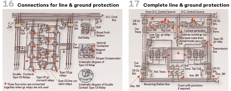
In medium resistance grounded neutral system, CO-relays were used, added with CD. (Figure 16).
In high resistance grounded neutral systems protection against wire-to-ground faults on high-resistance-grounded neutral systems cannot readily be provided unless the magnitude of the ground current in the circuit and the ratio of the current transformers are such as to produce 1 or 2 amperes in the secondary of one current transformer with a ground fault on that wire.
Since the ground current is less than the load current in the circuit to be protected, a directional element which shall be independent of load is required. Figure 17 shows complete line and ground protection for two parallel lines on a high-resistance-grounded neutral system.
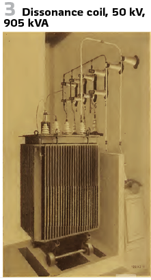
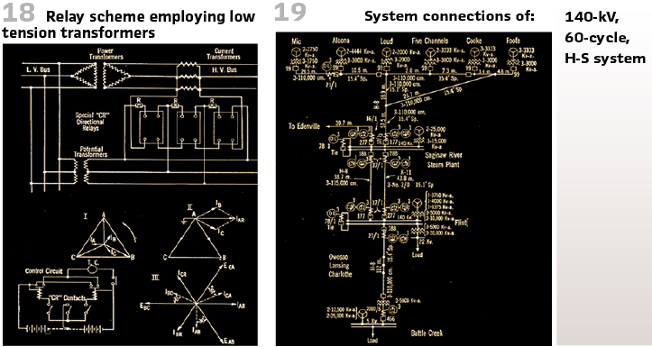
In 1927, Breiskyi, North and King published a paper at AIEE on “Directional Ground Relay Protection of High-Tension Isolated Neutral Systems.” This paper discussed the problem of obtaining selective relay protection in case of accidental grounds on high-tension isolated neutral systems. A relay was developed whose overcurrent element operates on the residual charging current which exists, when a ground occurs on such a system, and whose directional element is operated by residual charging current and residual voltage. Two schemes could be employed: One using high tension potential transformers for energizing the voltage coil of the directional element. The other, which is more complicated but cheaper, makes use of low-tension potential transformers.
Tests were undertaken in the 140-kV system of Consumer Power Co to determine the effectiveness of this relay system in conditions of arcing and solid grounds. These tests were successful and it was decided to make general use of this equipment. The relay scheme was put into operation in March of 1926. (the Figure on page 70).
Figure 18 shows the scheme, and Figure 19 the system connections.
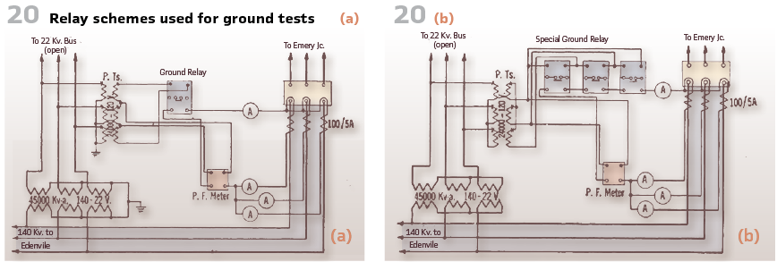
The relay schemes used for ground tests are shown in Figure 20.
Figure 20 A shows the high-voltage potential transformer scheme, while Figure 20 B shows the low-voltage.
info@walter-schossig.de www.walter-schossig.de
thomas.schossig@omicronenergy.com
Biographies:

Walter Schossig (VDE) was born in Arnsdorf (now Czech Republic) in 1941. He studied electrical engineering in Zittau (Germany) and joined a utility in the former Eastern Germany. After the German reunion the utility was renamed as TEAG, Thueringer Energie AG in Erfurt. There he received his master’s degree and worked as a protection engineer until his retirement. He was a member of many study groups and associations. He is an active member of the working group “Medium Voltage Relaying” at the German VDE. He is the author of several papers, guidelines and the book “Netzschutztechnik
[Power System Protection]”. He works on a chronicle about the history of electricity supply, with emphasis on protection and control.
Thomas Schossig (IEEE) received his master’s degree in electrical engineering at the Technical University of Ilmenau (Germany) in 1998. He worked as a project engineer for control systems and as a team leader for protective relaying at VA TECH SAT in Germany from 1998 until 2005.
In 2006 he joined OMICRON as a product manager for substation communication products. He is author of several papers and a member of standardization WGs.