by Anick Pomerleau, Eric Thibodeau, Samuel Gouin, Hydro-Quebec, Canada
Hydro-Quebec’s power grid is predominantly radial, with approximately 85% of electricity generation concentrated in Northern Quebec and about 85% of the electricity load in the southern part of the province. This results in roughly 1000 km separating generation from consumption. The extensive use of the 735 kV transmission system, spanning over 12,500 km, is characterized by a relatively small number of long transmission lines located along two main axes. While this configuration is required to efficiently transport electricity over such distance, it also makes the transmission system more sensitive to events that could lead to a collapse of a large part of the network.
During the 1990s, Hydro-Quebec made significant efforts to enhance the reliability and security of its grid. The utility designed a fully automated Defense Plan based on the following principles:
- Ensure service continuity without the assistance of Remedial Actions Schemes (RAS) in the case of likely events
- Take measures to prevent a general outage after extreme events
- Avoid damage to strategic equipment in the case of a general outage
- Enable system restoration within a reasonable timeframe following a catastrophic event
The RPTC RAS
The Generation Rejection and Remote Load Shedding system (RPTC acronym in French), a very important automatism of Hydro-Quebec’s Defense Plan, aims to avoid general outages during extreme events. Examples of such events include losing the generation from an entire power plan, tripping of multiple 735kV transmission lines, or bypassing of series compensation.
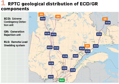
RPTC operates independently across four different corridors, rejecting up to 5 000 megawatts of generation at four different sites (GR) and remotely shedding up to 3 500 megawatts of loads (RLS) and 1 500 megavars of shunt capacitors. (Figure 1).
The logic of the RPTC RAS in the high-voltage substations relies mainly on two functional components:
- ECD: Extreme Contingency Detection unit (UCE in French)
- GR: Generation Rejection unit (URP in French)
To ensure the grid stability, the generation rejection action of RPTC must be completed within a maximum of 180ms, including the telecommunications time budget allowed to send the signal over 1000 km, from the ECD to the GR.
RPTC and its components have been in service since the late 1990’s. Both the ECD and the GR are implemented in a GE Fanuc PLC (Programmable Logic Controller) (system A) and a Siemens TI PLC (system B). Their logic is coded using Ladder language and uses more than 500 wired inputs / outputs.
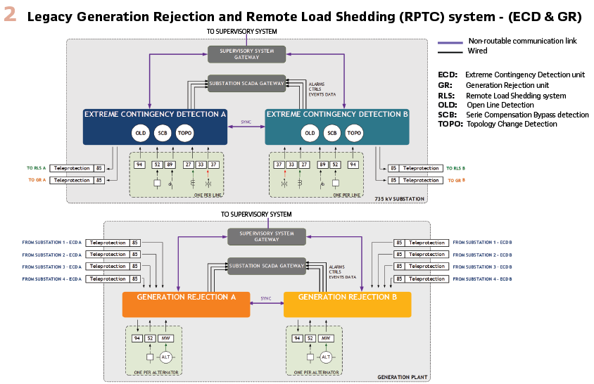
ECD: The detection of 735 kV transmission line loss and series compensation bypass is made by the ECD. Those detections are made using line protection trip signals, undercurrent relays, high-voltage switchgear position contacts, and series compensation bypass circuit breaker contacts and protection trip signals.
Among multiple wired inputs and outputs, the ECD publishes many statuses and alarms to the substation SCADA system. Most importantly, the ECD publishes the events to be sent to the GR using teleprotection units (C37.94). (Figure 2).
GR: The GR receives events from all ECDs within the corridor, and initiates production rejection by tripping the alternator circuit breakers at the generation plant where it is located. The amount of power to be rejected is conditioned by a central / provincial supervisory system, ensuring that RPTC acts in accordance with the real-time state of the grid.
Both GRs (systems A and B) continuously exchange substantial volumes of data to maintain synchronization. This ensures coordinated responses and guarantees that identical decisions are made whenever an exceptional event is detected on the grid.
The Replacement Solution: Transition to IEC 61850
The RPTC replacement solution introduces significant changes to the RAS architecture deployed in strategic substations.
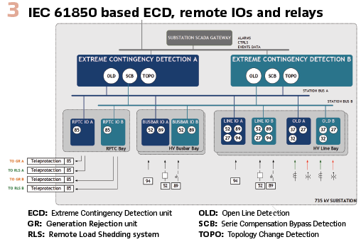
The intelligence and the algorithms for topology change detection and generation rejection are now decoupled from the inputs/outputs. Instead, inputs and outputs, such as switchgear position contacts or line protection trip signals, are distributed through remote IOs installed near the signal sources. They are routed to the new ECDs of both systems A and B via GOOSE, using PRP on their respective station bus. Additionally, SCADA communication (signals, commands, and alarms) is fully implemented through MMS protocol, which eliminates the need for numerous physical I/O connections.
The individual replacement of RPTC per substation is simplified by reusing current communication channels and tele-protection units (C37.94).
This technological shift is driven by the anticipated modernization of the grid planned in the next 5-10 years, which is essential to support the energy transition and associated increase in electrical loads. (Figure 3).
The IEC 61850 migration of the RPTC RAS brings several advantages:
- The installation of remote IOs and relays that convert electrical signals to GOOSE near the signal source reduces cable lengths, thereby minimizing the risk of parasitic voltage on antenna circuits, which can cause misoperations
- The use of PRP minimizes the odds of communication failure. Both ECDs subscribe to GOOSE messages of various relays and remote IOs from both systems A and B, enhancing overall system availability in the event of an IED failure
- Once digitalized, the signals acquired by RPTC remote IOs are available for future RAS needs
- During future substation upgrades, protection relays and new switchgear equipment should be able to directly publish their data via GOOSE, allowing the removal of remote IOs that convert binary signals, and therefore speeding up detections
- More data can be published to external systems via communication protocols, including Sequence Of Events (SOE) recorders. Also, the IEC 61850 modeling facilitates data interpretation at all levels
- The portability of ECD/GR algorithms to other platforms that support IEC 61131-3 programming and IEC 61850 GOOSE and MMS communications is simplified
Developing the Programmable Logic
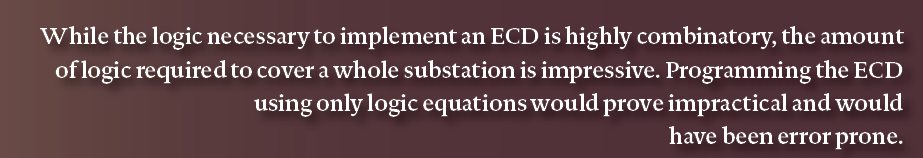
While the logic necessary to implement an ECD is highly combinatory, the amount of logic required to cover a whole substation is impressive. Programming the ECD using only logic equations would prove impractical and would have been error prone.
The obvious choice to develop the system was to resort to a Programmable Logic Controller (PLC) using IEC 61131-3 as development language. Moreover, special care was taken to select a PLC that did support the third edition of the standard, which allows Object-Oriented Programming (OOP).
Object-Oriented Programming in IEC 61131-3: The concepts behind Object-Oriented Programming were born in the early 1960s, Simula being recognized as the first language that allowed it. It is now well established that OOP helps developers to better organize and modularize their code. It also greatly improves code reuse, and maintainability.
Despite such advantages, the concepts of OOP took more than fifty years to make their way to PLC languages. The third edition of IEC 61131-3, published in 2013, was the first to allow OOP. Needless to say, it is not yet supported by all PLC manufacturers.
Adding OOP to IEC 61131-3 is not a huge leap when you have a look at the base language. Regardless of the language they use (Structured Text for example), PLC programmers organize their code into three types of Program Organization Unit (POU): Functions, Function Blocks and Programs. The second type, Function Blocks, maintain their state over time between every call. Now in short, the definition of an object is a programming structure that encompasses both data and behavior. Functions Blocks already have ”member” data that is accessible only from the object context. All Function Blocks needed to become objects was the ability to add them methods. Add inheritance and interfaces in the mix, and a Function Block is now equivalent to a class in any modern OOP language.
Being able to design IEC 61131-3 PLC software using OOP allows developers to use the SOLID principles in their designs:
- Single responsibility: classes should have only one intent
- Open-closed: classes are open to extension to increase their functionality, but closed to modification, disallowing direct external access to their data
- Liskov substitution: classes should be able to use other objects including all their derived objects interchangeably
- Interface segregation: classes should not depend on interfaces they do not use
- Dependency inversion: classes should depend on interfaces, not on concrete implementations
These are the principles that were followed in the design of ECD and GR.
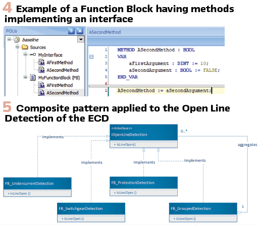
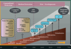
OOP applied to the ECD and GR: To give an example of how OOP can be used in the design of the RPTC PLCs, we will provide an example that concentrates on the detection logic at the core of the ECD. The intent of the ECD is to issue events upon detection of transmission lines being deenergized. As seen in Figure 3, several conditions may be used to detect a line being deenergized.
For example, a detection could be based on undercurrent, or on switchgear positions. It may even be anticipated from a trip signal being issued by a protection. And in some specific cases, transmission lines going through a substation not equipped with an ECD may require combining the detection results for more than one line.
Using OOP to develop the system enables the use of design patterns. While very specific, the requirements exposed above can all be fulfilled by a few basic building blocks that implement a Composite pattern. This is widely used in many IT applications where you need to construct a hierarchy of leaf and composite elements. Figure 5 illustrates how the different objects are related.
That design allows virtually any combination of detection elements to produce an indication that a transmission line is open. This can in turn be used by the event generation unit of the system in a transparent manner, regardless of the detection methods that are used. The other portions of the automation that use the interface do not need to depend on how the detections are implemented.
Using interfaces and polymorphism in this way not only allows better encapsulation and modularization of the code; it also opens the door to Test Driven Development. The less Function Blocks (or classes) depend on each other, the easier it is to use Unit Testing in the long run, as will be seen further below.
Fallacies and pitfalls: From the experience surrounding the development of the RPTC ECD and GR, using Object-Oriented Programming raised various concerns among OT engineers and technicians. The most voiced concern was about the readability and understandability of OOP code to field technicians that will have to deploy and debug these automation systems.
It might be true that OOP uses more complex code constructs than procedural code. Making use of inheritance, interfaces and encapsulation may make a program more difficult to understand to a non-initiated. The learning curve looks steeper, but understanding OOP automation code is within the reach of all OT practitioners; it is only a matter of training and experience.
This experience may require time and resources. However, utilities that take down this path will benefit from the investment in the long run. Object-oriented code is leaner, requiring less lines of code to perform the same job. And according to countless IT studies, less lines of codes directly result in less bugs.
While using OOP brings several advantages, using it in IEC 61131-3 still has some pitfalls. The most irritating one encountered during this development was related to the order of construction of objects. In opposition to more modern languages, IEC 61131-3 does not guarantee the order of construction of objects. Neither it allows to pass down constructor arguments to object members from an object that contain them. Our solution to that culprit was to disable the automatic constructions of objects that were instantiated within another object, and to explicitly invoke their constructor later during execution. The solution is not elegant, but it allows the desired behavior.
Testing Strategy
In addition to shaping the design and development methodology, IT orientations also influenced the testing strategy of the RAS. The validation of the solution is divided into five major testing phases. The common thread among these phases is the extensive use of automated tests, which cover both typical execution cases and anomalous situations that can only be generated through simulation.
The OOP approach to IEC 61131-3 programming has made it possible to verify incrementally both the development of PLC functions and the automated test programming associated with these functions. The effort and money invested in setting up the tests are significant, but it is justified by:
- The expected functional evolutions for the system in the context of the energy transition, and the technological/cybernetic evolutions that will inevitably be required in the coming years
- The use of a single IEC 61131-3 code base for all PLC performing the ECD or GR function. This code base will also be used for our future modernization of other RAS
Unit Testing: Unit testing is a concept directly derived from software development methodologies, and it is adapted to a PLC implementing complex logic, such as the ECD and GR. Unit Testing is widely proven in the IT world, though some frameworks are now available for PLCs. Despite the effort required to program and maintain the unit tests, their benefits are obvious, including:
- Early error detection and identification of faulty components
- Ease of modifications and maintenance of the code without affecting the stability of the system and existing components
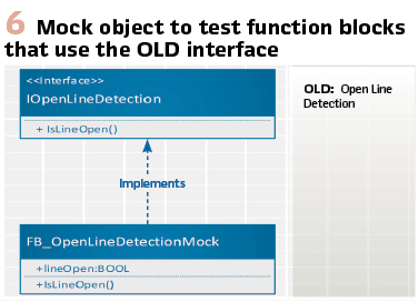
As described above, the use of interfaces enables the implementation of unit tests that focus on the functional aspects of single Function Blocks. When a Function Block only depends on interfaces, and not on actual implementations (Dependency inversion principle), it does not care what other Function Block it is using. This means that any interface can be mocked. A Mock is a simple implementation of an interface that allows easy manipulation of results returned by the methods that need to be implemented for a given interface, as showed in Figure 6. To implement the unit tests on a specific Function Block in a good OOP design, one only needs to instantiate the Function Block under test, and the Mocks of the interfaces it uses.
Such tests can be fully automated. Unit tests programming is done within the PLC’s development environment, usually by the PLC programmers. They do not require a simulation environment, as they run directly on the PLC, in test configuration POU.
Module Testing: Module testing is the closest thing to validation typically carried out on IEDs. It ensures that an equipment behaves as expected from an outside point of view.
Since RPTC now decouples its main algorithms from its electrical inputs /outputs, module testing is applied to each type of IEDs:
- Remote IOs:
- Since the inputs/outputs are distributed across several standardized remote IOs, the module test for those IEDs requires a limited number of inputs/outputs (typically 20 to 30 inputs and less than 20 outputs – compared to more than 500 inputs and outputs in the first version of RPTC). Those tests were mainly done using our integrated testing environment (see Figure 7,) since we had already all the wiring done with different variations of the remote IOs configurations
- A commercial relay test and commissioning tool was also used to validate this type of IED. The test sequences programmed within the tool enable verification of the simple logic that is implemented, and of the electrical-to-GOOSE or GOOSE-to-electrical conversion performance
- Undercurrent relays:
- These relays use specialized algorithms to detect the opening of a 735 kV transmission line. They are tested using various use cases based on network simulations and COMTRADE files recorded from past events on the network. The relays must detect the absence of current quickly (less than 30ms), while avoiding any spurious detections.
- A commercial relay test set is used to verify the IEC 61850 model, the specific protection functions, as well as the physical inputs/outputs and the GOOSE performances.
- PLC implementing the programmable logic of ECD/GR:
- As the PLC has no wired inputs/outputs, its module tests are performed using an IEC 61850 GOOSE / MMS simulator, which can act as both client and server. The complexity and speed of the PLC and the amount of data that is involved in a test scenario justify the programming and automation of the simulation and associated validation of the response behavior
- The validation strategy is time-based: for a given test case, the server part of the simulator emulates the PLC’s execution environment (remote IOs, undercurrent relays, SCADA gateways, supervisory system), while the client part of the simulator logs all GOOSE and MMS transitions received by the PLC in response to the test case. These transitions are afterwards compared with the anticipated behavior: all expected transitions must be recorded by the client within the expected times, with no unexpected transitions. A time tolerance of a few milliseconds ensures a certain flexibility in validation
- Full IEC 61850 module testing covers functional as well as performance/speed, safety and reliability aspects of the PLC’s implementation. Automated test programming adds an element of randomness to testing, going beyond common operating scenarios. This enables the verification of error cases that are not possible with a realistic execution environment, thus verifying the robustness of the ECD/GR
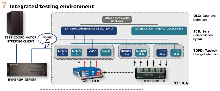
Integrated Testing: The Integrated testing phase aim to confirm the correct operation of the entire system, including the switches constituting the LAN, particularly the station busses, as well as the clock and firewalls. They detect potential incompatibilities between the various IEDs, as well as timing problems or execution dynamics specific to a realistic substation environment. They cover end-to-end functional, performance and stability tests for typical and abnormal scenarios, also adding a randomness in each test execution, and verifying expected and unexpected behaviors for all IEDs of the environment.
The Integrated Testing environment includes two partial and two fully replicated sub-environments, that contain the RPTC infrastructure. The last two act as replicas for an 8-line substation (distributed across 3 different buildings) as well as a 3-line substation / generation plant. Altogether, the environment comprises 81 IEDs, 19 cabinets, 58 switches, 8 firewalls and 4 clocks. Wiring and engineering practices mirror those used in live deployments. The high number of switches reflects the complexity of the multi-building architecture, the segregation of systems A and B, as well as the deliberate choice to create four distinct, isolated replicas. Also, the interconnection of all four replicas is enabled to constitute a complete RPTC corridor, enhancing system testing.
The integrated testing environment is driven by Hypersim, a sophisticated grid simulator developed by OPAL RT and Hydro-Quebec. Hypersim coordinates all necessary wired and virtual inputs and outputs, more specifically:
- Over 144 wired outputs (simulating switchgear positions, protection trip signals, …) as inputs to remote IOs
- 48 wired inputs, receiving event tele-protection and generation breaker trip signals, interfacing with remote IOs outputs
- 48 Sampled Values relayed by OMICRON amplifiers into current and voltage outputs, connected to undercurrent relays
- 1420 GOOSE subscriptions, incoming from all IEDs throughout the test environment
- 73 published GOOSEs, to simulated additional IEDs
With a step of 100 µS, Hypersim enables a high volume of transitions of both wired and virtual I/Os (via GOOSE), effectively stressing the IEDs and generating realistic bursts of changes that simulate real-world conditions.
The integrated tests are executed each time a new version of the ECD or GR is issued. It is intended to maintain this test environments for the entire life of the system, to facilitate upgrades and maintenance. (Figure 7).
Factory Acceptance Tests: The main objective of the Factory Acceptance Tests (FAT) is to verify the integration of the solution before its deployment in the substation. These tests aim to ensure the integrity of all the wiring inside the panels and validate the configuration of all IEDs.
Test sequences programmed in a commercial relay test set are used to verify each IED. Additional validations cover non-OT components, such as the switches, the clock, the firewall and the IT services. This ensures that the whole system operates correctly.
Limited Operational Phase: The User Acceptance Tests: The final test phase takes place in production, at the substation or generation plant where the RPTC system is to be replaced. The new infrastructure (LAN, IEDs, etc.) is installed in parallel with the legacy RPTC PLCs. As a result, the new system receives the same inputs as the legacy system, but its action is redirected to an event recorder. This limited operational phase is carried out for 6 of the 16 installations (for the other 10 installations, the infrastructure is deployed in parallel, but there is no limited operational phase).
During this supervisory go-live, a weekly analysis is conducted on the new RPTC system, comparing its action and performance with the legacy system in response to voluntary / involuntary events. The weekly cadence is sufficient, as topological changes in production are relatively rare.
The goal of the limited operational phase is for the users to build confidence in the new RPTC. It allows maintenance teams to familiarize themselves with the system and the technological change. From an operational point of view, it is an opportunity to adapt the monitoring strategies and develop SCADA and control center displays.
At this point, the types of anomalies addressed were all minor:
- Addition of new alarms, and adjustment to the timing of existing alarms
- Minor adjustments to local PLC displays
The main observations made during this period are:
- The new RPTC system is significantly faster, even though there is more equipment in the chain (remote IOs)
- The additional IEC 61850-modeled supervisory data allows for detailed system monitoring, which is expected to positively impact the overall availability of RTPC during maintenance operations
Conclusion: The design and OOP of RPTC PLCs, and the modular infrastructure of the whole system, should provide important leverage for the development of future RAS and the replacement of existing ones. The adopted testing strategy helped deliver a stable and compliant implementation of RPTC, and should contribute to the long-term maintenance and support of the system.
Future directions:
- To reduce dependency on a single supplier, activities to transfer the ECD / GR implementation to other PLCs should be planned. The use of Object-Oriented Programming and pointers in IEC 61131-3 could complicate the transition, as edition 3 of the standard is not uniformly supported by the different platforms
- Continued development should include support for simulation mode, allowing for more robust testing and validation of configurations both before deployment and during maintenance activities
- Adding application layer security to IEC 61850 MMS communications to enhance adhesion to defense-in-depth principles should be envisioned
- The modernization of tele-protection units is required in upcoming years. Replacement solutions considered involve using an IED with the capability to convert GOOSE to C37.94, or the direct communication between the PLCs using GOOSE messaging over the WAN. Special attention must be given to safely and securely support this functionality
- The evolution of the network will see the integration of new substations, transmission lines and distributed wind farms to meet the growing demand for electricity. RPTC algorithms will need to evolve and consider the impact of these additions, particularly the fact that wind farms need to be rejected first to guarantee grid stability, as alternators have more inertia.
Biographies:

Anick Pomerleau is an Automation Engineer in the Remedial Action Schemes team at Hydro-Quebec. She has been working in the energy sector and with utilities for over 20 years. Her past experiences include embedded systems software development and project management for SCADA and automation system replacements. Anick completed a bachelor’s degree in computer engineering from École Polytechnique de Montréal in 1998, graduating with honors, as well as a Specialized Graduate Diploma (DESS) in Engineering Management from Université de Sherbrooke. She is a Registered Professional Engineer in the province of Quebec.

Eric Thibodeau is an Automation Engineer at Hydro-Quebec. His prior experiences include being Product Manager for Protection products at Gentec, and Software Developer specialized in communication protocols at Eaton. He is involved in the activities of the IEEE PSCCC and IEEE PSRCC. Formerly, he obtained its B.Ing. in Computer Engineering, as well as M.Sc.A. and Ph.D. degrees from Universite de Sherbrooke. While a graduate student, he was also a lecturer in this same institution about network protocols specification and design, network components and architecture as well as electronic power supply design. His main areas of expertise are TCP/IP networking, SCADA communication and cybersecurity, and digital protective relaying. He is a registered professional engineer in the Province of Quebec.

Samuel Gouin graduated from Polytechnique Montréal in 2014 with a bachelor’s degree in electrical engineering. Since then, he has been working at Hydro-Québec in Automation, specializing in the deployment of IEC-61850 protection & automation systems in high voltage substations. Samuel has also contributed to the modernization of large RAS at Hydro-Quebec, from designing solutions to deployment. He is a registered professional engineer in the Province of Quebec.