By Alex Apostolov, PACWolrd, USA
IEC 61850 has been identified for more than twenty years as a cornerstone technology for the Smart Grid. One of the key components that gives it this role is the Generic Object-Oriented Substation Event (GOOSE) message that supports peer-to-peer communications between multifunctional Intelligent Electronic Devices (IEDs) which meet the high-speed performance requirements of protection and automation applications.
It was originally designed as a non-routable message used within the substation over the local area network. The success of using GOOSE messages for substation protection applications makes it attractive for use in wide area protection systems. These are applications that impose different requirements on the peer-to-peer communications.
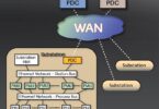
Even that GOOSE messages have already been used in protection and automation applications outside of the substation, the fact that they are transmitted over wide area networks makes them vulnerable to cyber-attacks. In order to address such concerns IEC TC 57 Working Group 10 developed the technical report IEC 61850 90-5, which defined the communications of synchrophasors and GOOSE over wide area networks. The communications are based on the full seven-layer OSI stack and use TCP/UDP multicast. The document also describes the use of end-to-end cyber security based on the definitions in the IEC 62351 standard.
The availability of secure peer-to-peer communications allows the use of R-GOOSE messages in distributed wide area protection systems. The bi-directional exchange of information between field IEDs and the System Integrity Protection Schemes controller is for the monitoring of the power system, as well as for the execution of required actions to isolate faulted sections and maintain the stability of the electric power grid.
System Integrity Protection Schemes
System Integrity Protection Schemes (SIPS) are distributed applications based on exchange of information and control signals between intelligent electronic devices located in different substations or feeders throughout the electric power system.
They play a very critical role in maintaining the reliability of the electric power system through different advanced protection and control functions, such as:
- System reconfiguration
- Adaptive protection settings control
- Distributed energy resources control
- Load management
- Load shedding
SIPS can be considered as systems that have three main types of functional elements:
- System monitoring elements
- Protection elements
- Execution elements
The function of the system monitoring elements is to:
- Detect a change in the electric power system topology
- Detect a change in system load
- Detect a change in generation
The function of the system integrity protection is to determine if any of the above changes or their combination represents a threat for the stability of the electric power system. If there is a possibility for a local or wide area disturbance, it needs to make a decision and send signals for some action required to prevent the disturbance or at least limit the effect from the event.
The function of the execution elements is to receive the signals from the SIPS and execute locally the required action.
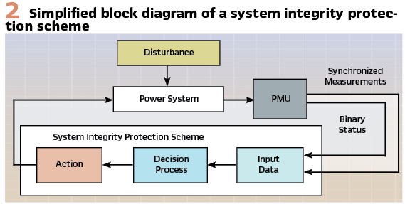
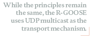
SIPS can be simple and complex with different number of levels in the hierarchy depending on the complexity of the system. Figure 2 shows a multilevel SIPS that uses multifunctional protection IEDs as the devices at the monitoring and execution levels of the system.
A wide area protection system requires different types of communications:
- Between multifunctional intelligent electronic devices (IEDs) at the bottom of the hierarchy and the substation level (Local SIPS)
- Between SIPS at the same levels
- Between the different levels of the SIPS
- Between SIPS and smart loads
All of the above communications interfaces may be based on different protocols and use different types of communications links. IEC 61850 is playing an increasingly important role due to the significant benefits that high-speed peer-to-peer messages play in the implementation of different functional elements of the scheme. The monitoring functions are typically based on:
- Current, voltage, active and reactive power measurements
- Synchrophasor measurements
- Monitoring the status of breakers and disconnecting switches associated with transmission lines, transformers and generators
The execution elements usually operate a breaker or other switching device in order to perform a specific action such as system reconfiguration or to reduce the load. They may also reduce the output of a distributed generator or completely shut it down.
GOOSE versus R-GOOSE
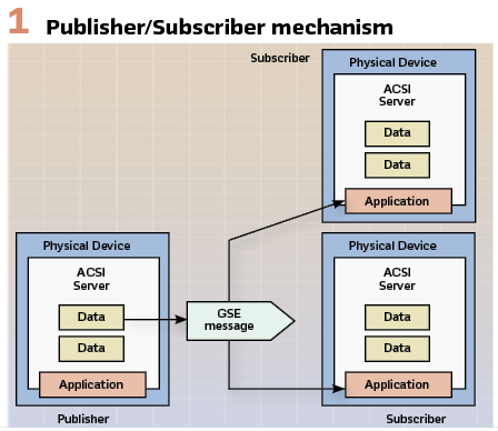
Peer-to-peer is the characteristic communications type for the IEC 61850 based systems. It is one of the distinguishing features of the standard that makes it attractive to protection and control specialists. It describes the ability of arbitrary pairs of IEDs connected to the substation network to manage the exchange of information as necessary with all devices having equal rights, in contrast to the master/slave communication. High-speed peer-to-peer communications in IEC 61850 based protection and control systems use a specific method designed to meet a variety of requirements. It is very important that the concept of the Generic Substation Event (GSE) model is not based on commands, but on the sending indication by a function that a specific substation event has occurred. It is designed to support reliable high-speed communications between different devices or applications and allows the replacement of hard-wired signals between devices with communication messages exchange while improving the functionality of the protection, automation and control system. It uses a connectionless Publisher – Subscriber communications mechanism shown in Figure 1.
The model includes several features that can be used to improve the reliability and availability of the system. At the same time the proper use of these features in vendors’ implementation will allow the reduction in maintenance and increase in the flexibility of the system. Initially GOOSE was developed for substation communications, but due to the benefits that it provides there was a need to define how it can be used for substation-to-substation or wide area communications.
To understand the differences between the substation GOOSE and the wide area GOOSE, we need to look into some of the details of the Generic Substation Event model.
The GSE method can be considered as a mechanism for reporting by a logical device. The achievement of speed performance, availability and reliability depends on the implementation in any specific device.
The GSE model is used to exchange the values of a collection of Data Attributes defined as a Data Set. GOOSE supports the exchange of a wide range data types organized in a data set.
The publisher writes the values in a transmission buffer at the sending side and multicasts them over the substation local area network to the different subscribers. The data in the published GOOSE messages is a collection of values of data attributes defined as members of a data set. The receiver reads the values from a local buffer at the receiving side. A GSE control block in the publisher is used to control the process. If the value of at least one of the DataAttributes has changed, the transmission buffer of the Publisher is updated with the local service “publish” and the values are transmitted with a GOOSE message.
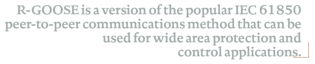
The publisher/subscriber mechanism allows the source IED to reach multiple receiving IEDs thus significantly improving the efficiency of the communications interface. In substation communication networks this is based on the use of a MAC multicast destination address in the Ethernet frame shown in Figure 3 where:
Destination address (6 bytes) identifies which station(s) should receive the frame
Source addresses (6 bytes) identifies the sending station
Length is 6 Octets and contains the value of the destination Media Access Control (MAC) address to which the GOOSE message is to be sent. The address shall be an Ethernet address that has the multicast bit set TRUE.
If a port has an 802.1Q-compliant device attached (such as another switch), these tagged frames can carry VLAN membership information between switches, thus letting a VLAN span multiple switches.
Specific communication services in the subscribers update the content of their reception buffers and new values received are indicated to the related applications.
Since the GOOSE messages replace hard-wired signals used for protection and control applications, IEC 61850 introduces mechanisms that ensure the delivery of the required information.
Once a new value of a data attribute has resulted in the multicasting of a new GOOSE message, the repetition mechanism ensures that the message is sent with a changing time interval between the repeated messages until a new change event occurs.
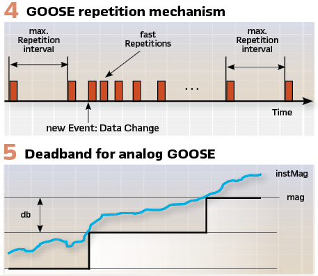
As shown in Figure 4, at the beginning after a change the interval is very short – a few milliseconds, which later increases until it reaches a value of a few seconds. This method achieves several important tasks:
- Ensures that a loss of a single message is not going to affect the functionality of the system
- Allows any new device to inform all subscribing devices about its state
- Allows any new device to learn the state of all publishing devices it subscribes to
The GOOSE messages contain information that allows the receiving devices to know not only that a status has changed, but also the time of the last status change:
- T –time stamp representing the time at which the attribute StNum was incremented
- StNum indicates the current state number – a counter that increments every time a GOOSE message including a changed value has been sent for the first time.
- SqNum is the sequence number – the value of a counter that increments each time a GOOSE message with the same values has been sent. The value is reset to 0 after change in SqNum
At the same time the repetition mechanism can be used as a heartbeat that allows the continuous monitoring of the communications interface – something that is not possible in conventional hard-wired systems.
The state number and the sequence number can be used to detect intrusion, thus allowing significant improvement in the cyber security of the system without the need for encryption or other cyber security methods.
The Routable – GOOSE – (R-GOOSE) represents a significant advancement in power system communication technology. Building upon the foundation of the GOOSE defined in the IEC 61850 standard, R-GOOSE extends these capabilities to enable communication over wide area networks (WANs) and the internet, rather than being limited to local area networks (LANs).
Analog GOOSE (Figure 5) can be very useful in SIPS applications both at monitoring and execution locations. This is based on the fact that the members of the GOOSE data sets do not need to be only binary or integers but also can be analog values such as currents, voltages, frequency or active power. In this case an analog event that requires the transmission of a message with a new state number is defined by a dead band (db) for the magnitude or angle values of the measured values. (Figure 5).
While GOOSE operates at the data link layer (Layer 2) of the OSI model, using Ethernet multicast to deliver time-critical messages with minimal latency, R-GOOSE evolved from this foundation by incorporating IP-based (Layer 3) routing capabilities. While maintaining the core functionality of GOOSE, R-GOOSE allows messages to traverse network routers, enabling communication between geographically dispersed substations across WANs.
R-GOOSE utilizes User Datagram Protocol (UDP) multicast for communication over IP networks. This allows a single message to be sent to multiple recipients simultaneously, reducing network traffic compared to sending individual messages to each destination.
Publishers send messages to multicast group addresses, while subscribers receive messages by joining these groups, creating a streamlined publish/subscribe model. As a connectionless protocol, UDP eliminates the overhead associated with establishing, maintaining, and terminating connections, resulting in faster message delivery. The multicast approach scales efficiently as new devices can simply join existing multicast groups without reconfiguring publishers.
The Internet Protocol (IP) is a Layer 3 protocol. The Network layer adds the concept of routing above the Data Link layer. When data arrives at the Network layer, the source and destination addresses contained inside each frame are examined to determine if the data has reached its final destination.
If that is true, this Layer 3 formats the data into packets delivered up to the Transport layer. The IP allows the routing of data packets (IP packets) between different networks over any distance.
The User Datagram Protocol (UDP) is a Transport Layer 4 network protocol. While TCP (Transmission Control Protocol) is a connection oriented protocol that requires first to establish communications between a client and a server, UDP is connectionless, which makes it more suitable for GOOSE communications.
UDP network traffic is organized in the form of datagrams. A datagram comprises one message unit. The first eight (8) bytes of a datagram contain header information, and the remaining bytes contain message data.
A UDP datagram header consists of four (4) fields of two bytes each:
- Source port number
- Destination port number
- Datagram size
- Checksum
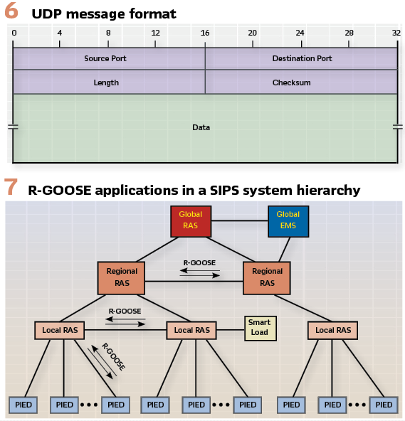
The UDP checksum protects the message data from tampering. The checksum value represents an encoding of the datagram data calculated first by the sender and later by the receiver. If the checksum does not match indicating a tampered or corrupted data during transmission, the UDP protocol detects it. In UDP the check sum is optional as opposed to TCP where it is mandatory. The many working applications of the IEEE C37.118 protocol confirm that the use of UDP for the streaming of the synchrophasor data is a proven method that can also be used for the routable GOOSE. (Figure 6).
R-GOOSE Apps in SIPS
The R-GOOSE described above has multiple applications in SIPS. It brings some significant benefits for wide area distributed applications, especially when they are based on wireless communications technologies. The cyber security features defined in IEC 61850 90-5 and IEC 62351 provide a high level of security, which is a key requirement for SIPS.
R-GOOSE can be used for both vertical and horizontal communications in hierarchical SIPS
The following are some of the main applications of R-GOOSE communications in SIPS:
- Exchange of load and power flow information between the local monitoring elements of the SIPS and the higher levels of the SIPS hierarchy based on analog R-GOOSE
- Exchange of breakers and switches status information between the local monitoring elements of the SIPS and the higher levels of the SIPS hierarchy based on R-GOOSE
- Exchange of aggregated load, power flow and status information between the higher levels of the SIPS hierarchy based on R-GOOSE and analog R-GOOSE
- Exchange of tripping and control signals between the higher levels of the SIPS hierarchy and the local execution elements based on R-GOOSE
GOOSE messages also play an essential role related to load-shedding in System Integrity Protection Schemes (SIPS). They are used to:
- Provide information about the changes in the loading of the system that can be used do define where to send the load-shedding commands in case of a wide area disturbance
- Provide information about the change of state of electric power system components such as transmission lines or power transformers that may trigger load-shedding
- Execute the load-shedding between the different layers of the wide area protection system hierarchy
As it is shown in Figure 7, R-GOOSE messages are used both as vertical (between the different levels of the hierarchy) communications or horizontal (between components of the SIPS at the same level of the hierarchy) communications.
The communications are bi-directional, since they are used on one hand to provide information to the SIPS about the state of the electric power grid, and on the other to send the information from the SIPS in order to execute the load-shedding or generation control.
The final stage of the load-shedding execution is implemented in the substation using a combination of R-GOOSE and GOOSE messages by a centralized load shedding system. It is also used in substations when it is executed as the result of operation of a remedial action scheme as shown in Figure 8.
In order to achieve adaptive load shedding the substation level controller receives analog GOOSE messages from the distribution feeder relays every time when there is a change in the load outside of the user defined tolerance setting. The load shedding controller uses this information to determine an optimal combination of loads to be shed based on the selected optimization criteria.
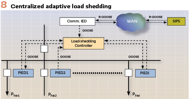
In case of a wide area disturbance the system integrity protection scheme sends an R-GOOSE message over the wide area network to the substation controller containing information about the amount of load to shed in the substation. This amount of load is then matched with the possible groups of feeder loads and a GOOSE message is sent to the substation network indicating which feeders need to be tripped in order to shed an amount of load as close as possible to the required value.
Any distribution feeder IED that belongs to the load shedding system and subscribes to GOOSE messages from the substation controller will receive the message and if it indicates that it belongs to the group of feeders to be shed, it will trip its associated breaker. Since a centralized load shedding system is subject to the failure of the load shedding device, a second backup IED may be required to ensure the reliability of operation in case of system disturbance.
Further improvement of the load-shedding execution can be achieved by using R-GOOSE to reach individual loads within the distribution system instead of tripping the substation feeder breakers and thus de-energizing the complete feeder.
Conclusions
R-GOOSE is a version of the popular IEC 61850 peer-to-peer communications method that can be used for wide area protection and control applications.
While the principles remain the same, the R-GOOSE uses UDP multicast as the transport mechanism.
R-GOOSE offers significant benefits for many different electric power system protection, automation and control applications, such as System Integrity Protection Schemes at the transmission level. It can be used for load-shedding related functions between the different levels of the SIPS hierarchy and also for the execution of the load shedding at the distribution level of the system.
Such applications will have a positive impact on the efficiency of the protection and control systems in smart grids.
Biography:

Dr. Alexander Apostolov received his MS degree in Electrical Engineering, MS in Applied Mathematics and Ph.D. from the Technical University in Sofia, Bulgaria. He is Principal Engineer for OMICRON electronics in Los Angeles, CA. He is an IEEE Fellow and Member of the PSRC and PSCC. He is past Chairman of the Relay Communications Subcommittee, serves on many IEEE PES WGs. He is a member of IEC TC57 WGs 10, 17, 18, 19, Convenor of CIGRE WG B5.86 and member of several other CIGRE B5 WGs. He is a Distinguished Member of CIGRE. He holds 4 patents and has authored and presented more than 500 technical papers. He is an IEEE Distinguished Lecturer and was Adjunct Professor at the Department of Electrical Engineering, Cape Peninsula University of Technology, Cape Town, S. Africa. Alex is a member of the National Academy of Engineering (NAE). He is Editor-in-Chief of PAC World Magazine.