By Farokh Aminifar, Dan Brancaccio, and Damir Novosel – Quanta Technology, Davis Erwin – PG&E, Steven Prsha, Will Ragsdale, and Robin Manuguid – SDG&E®, Marianna Vaiman and Michael Vaiman – V&R Energy, all from USA
While increasing use of electrical energy due to hyperscale data center integration and electrification opens new opportunities, the integration of inverter-based devices, including renewable generation, requires technological advancements to address challenges in maintaining power system stability, security, and reliability. Large-scale disturbances, such as the April 28, 2025, blackout in Spain and Portugal, also underscore the critical importance of advancing technologies to address emerging risks. In addition to addressing grid adequacy, inverter-based devices have been significantly altering the dynamics of the grid while introducing new and often unforeseen challenges. There have been multiple instances of unnecessary triggering of protection systems of inverter-based resource (IBR) and data center inverters due to faults on the transmission system. Frequency deviations occur more rapidly with less rotational inertia in the system, requiring faster response mechanisms. While IBRs reduce inertia, they offer the advantages of faster responsiveness and more flexible control. Advanced System Integrity Protection Schemes (SIPS) can leverage these capabilities by dynamically adjusting IBR output to counteract disturbances in real time.
Power systems have also become more tightly interconnected to address resource adequacy needs and provide grid reliability services. While it helps strengthen the grid, preserving system integrity and preventing the propagation of disturbances require the use of advanced technologies.
Fast developing outages have been addressed by SIPS, which have been widely used in practice, particularly in the systems affected by stability issues, such as the Western Electricity Coordinating Council (WECC). SIPS are automated protection schemes designed to detect predetermined or abnormal system conditions and take corrective actions to maintain the integrity of the overall power system. SIPS encompass special protection schemes (SPS), remedial action schemes (RAS), and a variety of other “safety nets.”
SIPS actions may include changes in demand, power transfer, generation, switch in/out of devices, and system configuration to maintain system stability, voltage, and power flow.
The evolution of power systems toward more dynamic behavior and energy adequacy issues makes the limitations of conventional approaches increasingly evident. Modern power systems demand faster, more accurate, and more coordinated control mechanisms capable of detecting abnormal conditions and initiating corrective actions in real time. This need has driven the development and deployment of advanced SIPS.
Advanced SIPS leverage enabling technologies such as phasor measurement units (PMUs), wide-area communication networks, and real-time data analytics to provide a more dynamic and flexible approach. They utilize system-wide information to detect instability patterns early, assess the severity of disturbances, and initiate coordinated control actions beyond the local level. Adopting advanced SIPS is a technological upgrade and a paradigm shift requiring reliable communication, robust decision-making algorithms, and the ability to integrate seamlessly with existing Supervisory Control and Data Acquisition (SCADA) and Energy Management Systems (EMS). Furthermore, validating and verifying the performance of advanced SIPS under realistic system conditions require thorough studies and often the use of real-time digital simulators. This paper presents a comprehensive overview of advanced SIPS (or RAS), their design, technology enablers, and practical applications.
Overview of SIPS
As power systems with large penetrations of renewable energy resources, storage, and data centers exhibit more dynamic behavior, designing systems that can deploy automated actions to address various scenarios is crucial. Disturbance propagation involves a combination of several phenomena, including equipment tripping, frequency instability, unintentional islanding, transient instability, small-signal instability, and voltage instability/collapse.
Traditional SIPS vs. Advanced SIPS: Traditional SIPS or RAS rely on predefined, static controls and remedial actions to address known contingencies and faults within a power system. These schemes typically include load shedding, generator tripping, or other actions triggered by specific fault conditions. While effective in certain situations, traditional SIPS have limitations in handling unforeseen disturbances, especially in increasingly complex and dynamic systems. They are often localized, with limited coordination across wide areas, making them slower to react to large-scale or cascading events.
Advanced SIPS leverage advanced technologies such as synchrophasor measurements, real-time data analytics, and wide-area communication networks to provide a more dynamic, system-wide approach to system integrity. They can monitor the grid in real time, enabling faster detection of disturbances and more coordinated, automated control actions across the system. These systems integrate decision-support algorithms, which analyze the collected data to predict potential system failures and initiate appropriate responses, such as adjusting generation or transmission flows. Advanced SIPS are also more flexible and scalable, capable of adapting to the increasing integration of renewable energy sources, data centers, and other technologies, ensuring better power system stability, resilience, and reliability.
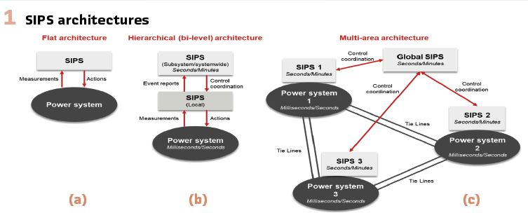
Classification of SIPS Architecture: SIPS architecture could be classified as flat and hierarchical based on purpose and operating times, as shown in Figure 1 (a) and (b). Flat architecture, measurements, and operating elements are typically in the same location. For hierarchical architecture, local measurements and a series of predetermined parameters at various locations are transmitted to multiple control locations, and decision processes and output actions involve multiple locations. The purpose of the scheme will drive the design. A hierarchical scheme may involve multilayers and will involve communication among various locations whereas a flat scheme involves a single layer of decisions and actions. In interconnected power systems, SIPS from neighboring areas can be coordinated under a global scheme, allowing for the exchange of critical information and coordinated control actions to improve the overall effectiveness of each individual area’s scheme, Figure 1 (c).
SIPS Adoption Criteria: The deployment of SIPS must follow strict criteria to ensure their effectiveness, safety, and compatibility with existing grid operations and coordination with neighboring systems. The design should be highly reliable and scalable for future expansions, achieving both secure and dependable operation, as SIPS failure can have huge consequences. SIPS are not a substitute for sound planning or infrastructure investments; rather, they serve as complementary tools for enhancing grid reliability and resilience.
Enabling Technologies and Engineering of Advanced SIPS
Synchrophasor Measurement Technology: Synchrophasor technology, enabled by PMUs, provides time-synchronized voltage and current phasors, and frequency measurements across the power system, offering real-time visibility into grid dynamics that traditional SCADA often misses. PMUs monitor the system’s dynamic state with sub-second resolution, enabling early detection of instability. Integrated into SIPS, PMU data supports fast, informed decisions based on real conditions, allowing adaptive, flexible responses to disturbances, especially with changing topologies or variable renewable generation.
Wide-Area Communication Infrastructure: A robust wide-area communication infrastructure is essential for advanced hierarchical SIPS, enabling rapid, reliable data and control exchange across the grid within critical timeframes. Key performance metrics include latency, bandwidth, reliability, and security, with deterministic, low-delay communications vital for responding to fast-changing events, like voltage collapse or frequency excursions. Common technologies include fiber optics, microwave links, and packet-switched networks that use protocols such as IEC 61850, IEEE C37.118, and IEEE 802.1 to ensure interoperability, time alignment, and low latency. Software-defined networking and segmentation further improve critical traffic prioritization.
State Estimation and Data Analytics: State estimation and data analytics are vital for decision-making in advanced SIPS, turning SCADA and synchrophasor data into real-time insights. Linear state estimation (LSE) uses high-speed PMU data to provide an accurate system state. In the context of SIPS, LSE forms the foundation for detecting abnormal conditions (such as angular separation, line overloads, or approaching stability/voltage limits) and enabling proactive actions when equipped with contingency analysis. Data analytics further identifies patterns and anomalies using machine learning (ML) and artificial intelligence (AI) that enables systems to learn from data. Integrating AI-driven analytics supports adaptive, scalable protection as power systems grow more complex.
Adaptive Protection and Control Methods: IBRs like wind and battery energy storage systems (BESS) can provide headroom to support system imbalance response (SIR) and fast frequency response (FFR) amid low inertia. However, IBR headroom varies. A wind turbine’s ability to provide SIR directly depends on its available kinetic energy, which can vary significantly with wind speed fluctuations. BESS can provide headroom more consistently, but their efficacy is dependent on state of charge. Beyond inertia challenges, addressing the sudden loss of generation supplying data centers is required to preserve system integrity. Leveraging control and communications technologies to utilize IBRs’ headroom is paramount.
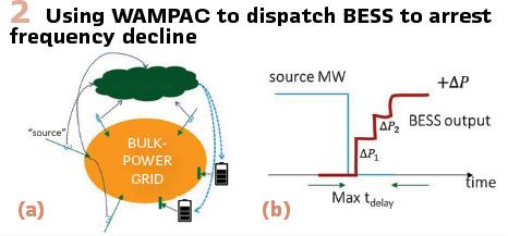
An example of deploying BESS to provide SIR using Wide Area Monitoring and Protection (WAMPAC) technology with synchronized measurements is shown in Figure 2. WAMPAC’s role is to monitor several generation sources to detect active power imbalance and communicate with several BESS units to detect the level of available active power. As shown in Figure 2(a), BESS units inform WAMPAC of their capability. Upon detecting sudden imbalance -ΔP, WAMPAC instructs each BESS to inject ΔPi so that ∑i ΔPi = +ΔP.
Figure 2 (b) shows that the maximum time delay is due to long-distance communications and the coordination of multiple devices. These types of control algorithms could be integrated into advanced SIPS.
High-Performance Computing (HPC): HPC enables advanced SIPS by providing computational power to process massive datasets and support real-time decision-making. As power systems grow more complex, HPC allows fast, large-scale simulations, testing of protection algorithms, and execution of wide-area control strategies. For example, HPC can simulate thousands of fault scenarios to develop robust inter-area oscillation damping controls. Beyond offline studies, HPC enhances online situational awareness with faster-than-real-time analytics, enabling SIPS to evolve into intelligent, adaptive systems that proactively prevent cascading failures.
SIPS Engineering: SIPS engineering includes the following categories:
- Equipment/hardware selection, including detection equipment, power supplies, batteries, and chargers, telecommunications equipment, etc.
- Monitoring and measurement functions and inputs selection, including status inputs, station alarms, SCADA monitoring, sequence of events recorders, and synchronized measurements, etc.
- Telecommunications and security selection, including network availability, monitoring, maintenance agreements, network cyber-security, etc.
- Interaction and coordination with protection and control systems to ensure that system configuration changes due to SIPS operation will not adversely affect protection and control functions (e.g., distance relay, overcurrent supervision, breaker failure pickup) and that transient or sustained voltage deviation during or after SIPS operation will not cause cascading outages
Case Studies in WECC
RAS in WECC are utilized to maintain or increase the transmission system capability, mitigate adverse system impact of certain low probability/high consequence system events, and prevent events from spreading out across large regions or onto wide area system. There are approximately 280 RAS in the WECC of which, the most used ones include generation trip, brake insertion, fast valve/generation ramp, HVDC ramp, configuration changes/islanding, load shed or rejection, excitation forcing, shunt capacitor/reactor switching, and series capacitor/reactor switching. They are designed, maintained, and evaluated in accordance with the WECC RAS Design Guide.
WECC identifies three types of RAS, depending on their potential impact:
- Local Area Protection Scheme (LAPS)
- LAPS constitute 66% of installed RAS at WECC
- LAPS type is used to meet an owner’s performance requirements within their system
- Wide Area Protection Scheme (WAPS)
- WAPS constitute 27% of installed RAS at WECC
- WAPS type is needed to meet WECC performance requirements and operating standards
- Safety Net (SN)
- SN constitutes 7% of installed RAS at WECC
- SN type is intended to minimize the impact of extreme events when such impacts cannot be entirely avoided
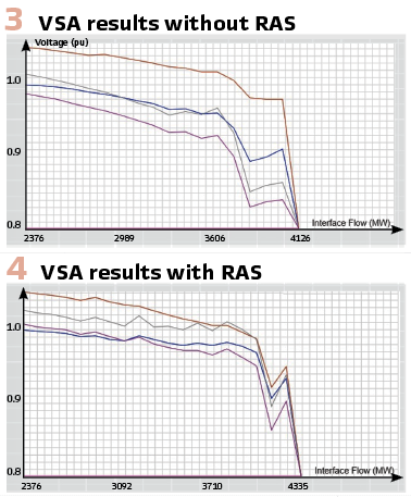
RAS actions have a significant impact on voltage stability limits in WECC. An example shown in Figures 3 and 4 illustrates how RAS actions impact the voltage stability analysis (VSA) results. Without RAS, post-contingency voltage collapse occurs at 4126 MW of interface flow (Figure 3), whereas when RAS actions are applied, the collapse point shifts to 4335 MW (Figure 4). Thus, considering RAS actions as part of the VSA, increases transfer capability by approximately 200 MWs for this voltage stability scenario.
Use of RAS during On-Line VSA at San Diego Gas & Electric®: San Diego Gas & Electric (SDG&E), a subsidiary of Sempra, is a regulated investor-owned utility in WECC that provides electricity to 3.6 million customers in San Diego and Southern Orange Counties. Its transmission ties in with four other entities in the Western Interconnection: Southern California Edison (SCE), Imperial Irrigation District (IID), Centro Nacional de Control de Energia (CENACE), and Arizona Public Service (APS). The company owns, operates, and is responsible for designing RAS needed to meet the requirements of its Planning Coordinator and Transmission Planner. (Figure 5).

On-Line VSA at SDG&E: SDG&E had traditionally been a voltage stability constrained utility. After over 30 years of studies resulting in important additions to the system, the utility reached a point where it is no longer voltage stability constrained. To get to this point, voltage stability studies and operating practices were performed using different tools. Since 2015, SDG&E has been running real-time version of the ROSE VSA software every 5 minutes. Two transfer scenarios are analyzed during on-line VSA:
- Scenario 1: Import Into SDG&E
- Scenario 2: Import Into SDG&E and CENACE combined
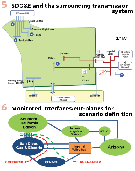
The cut-planes, or interface definitions, for these two scenarios are shown in Figure 6. There are two major 500 kV paths from Imperial Valley to the SDG&E bubble where single line contingencies, two on each path, are currently modeled during on-line VSA. RAS actions are modeled as scripts during VSA, which are invoked through the scenario files. RAS actions are automatically invoked provided that certain triggering conditions are met.
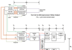
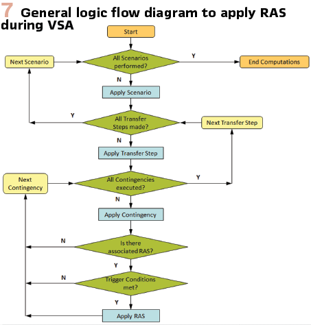
RAS Modeling during VSA: The process for modeling RAS actions during on-line VSA is shown in Figure 7. During each State Estimator cycle, trigger conditions and RAS actions are computed for all contingencies at each transfer step for all scenarios. The process described in Figure 7 is repeated every 5-minute cycle when a new State Estimator case arrives.
Five SGD&E RAS and 3 CENACE RAS are modeled during VSA.
The following five SDG&E RAS are modeled during VSA:
- RAS A: Designed to trip a calculated amount of generation, is enabled when all 500 kV lines west of Imperial Valley are in service. The total amount of generation that is tripped by the RAS is controlled by the California Independent System Operator (CAISO) and provisions are made to exclude generation from tripping, depending on the contingency. Operation includes:
a. Protects a 230kV line and prevents a CENACE RAS G from operating
b. Operates for contingency of any of the four 500kV lines
c. Mimics calculation in the microprocessor for calculating generation amount to be tripped
d. Instantaneously trips generation amount that was calculated in item (c) above - RAS B – E: When one of the four 500 kV lines is out of service, a RAS is enabled, which triggers the tripping of all the generation connected in the Imperial Valley Area that is in the CAISO Balancing Authority area. Operations include:
a. Protects CENACE internal lines
b. RAS is armed when planned outage of one of the four 500kV lines occurs
c. Loss of the remaining 500kV path trips all generation in the Imperial Valley area
The following three CENACE RAS are modeled during VSA:
- RAS F:
a. Detects for direction and overload on five line sections
b. Trips load sequentially in up to five locations in X seconds
c. A VSA has an option to stop stressing if this RAS is getting triggered - RAS G:
a. Detects for the same overload as RAS F
b. If After X seconds+ delay, overload is present and flow is southbound on CAISO-CENACE eastern connection:- During summer months: trips CAISO-CENACE western connection.
- During non-summer months: trips CAISO-CENACE eastern connection; trips units if overload persists
- RAS H:
a. Detects for southbound overload on CAISO-CENACE eastern connection
b. Trips load sequentially in up to five locations in Y seconds
c. Trips eastern connection if overload persists
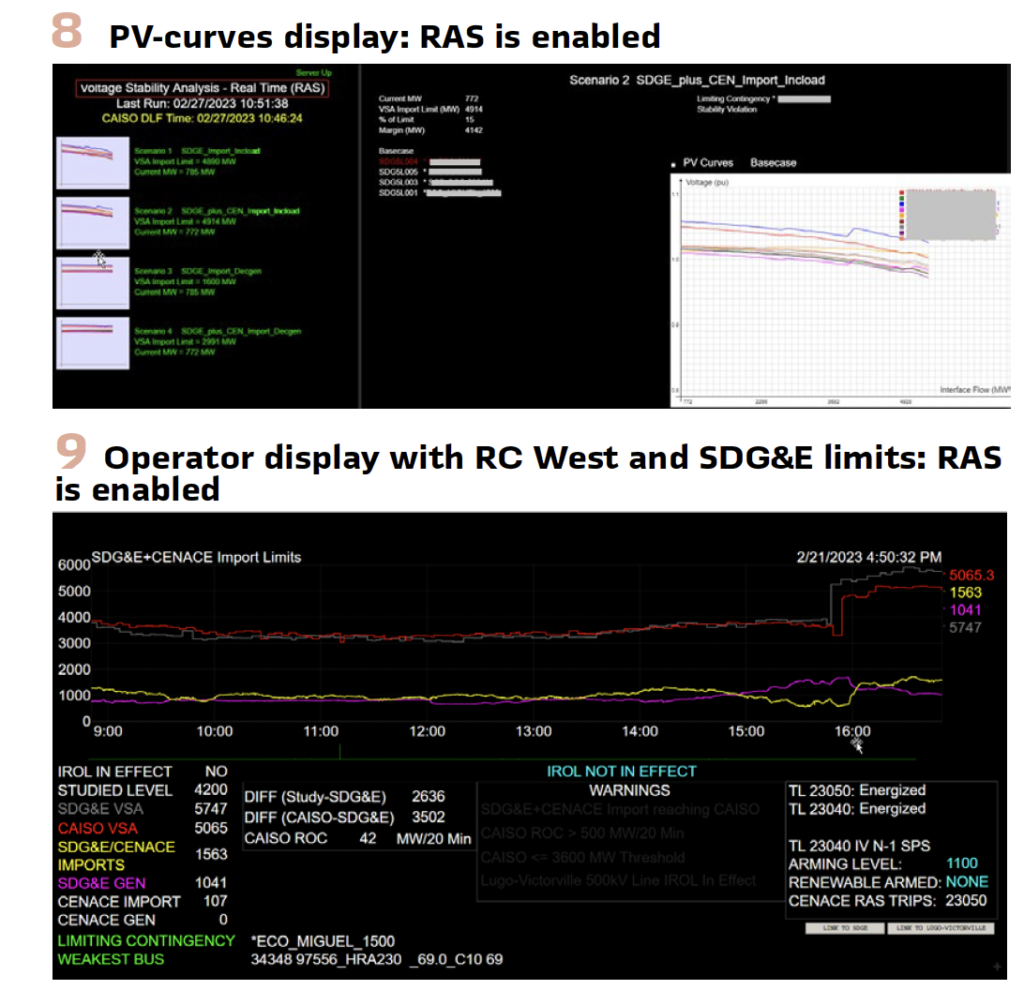
A PV-Curve display plotted during VSA, with RAS enabled, is shown in Figure 8. An operator display for VSA, with RAS enabled, is shown in Figure 9.
VSA is an important aspect of situational awareness for SDG&E. SDG&E-ROSE VSA software incorporates RAS during on-line voltage stability analysis, thus providing operators and engineers situational awareness based on actual system conditions and post-Contingency RAS actions.
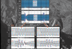
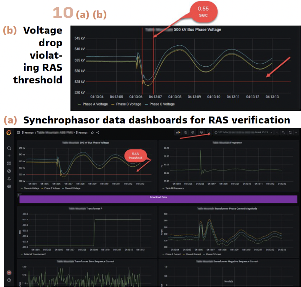
RAS Verification by Synchrophasor Data in PG&E: PG&E operates one of the most extensive and interconnected power systems in the United States, linking multiple utilities and balancing authorities. Given its scale, disturbances in PG&E’s territory can have widespread implications across the WECC. To mitigate large-scale disruptions, PG&E has developed sophisticated RAS, also known as SPS, that respond to grid contingencies in real time. PG&E utilizes PMUs primarily for post-event verification of RAS performance. The high-speed, time-synchronized measurements provided by PMUs allow engineers to analyze how RAS executed control actions during disturbances and assess their effectiveness. By correlating PMU data with RAS event logs (Figure 10), PG&E enhances the accuracy of models, identifies potential misoperations, and fine-tunes protection settings for future contingencies.
In alignment with NERC Standard PRC-012-2 and associated reliability guidelines, PG&E is required to periodically review and report the performance of RAS, including confirmation of expected operation during events and identification of any misoperations or failures to operate. PMUs play a critical role in meeting these obligations. Their precise time alignment enables engineers to chart event timelines with sub-second resolutions, offering clear visibility into whether a RAS operated as designed, delayed, or failed. This evidence-based verification supports compliance documentation and improves internal and external audit readiness.
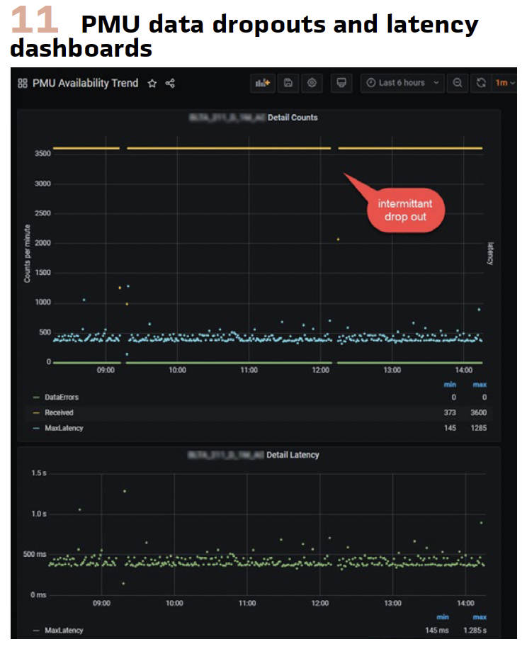
Because RAS-triggering events occur infrequently, it is essential to maintain a high degree of data readiness and visibility. To address this challenge, PG&E has developed Key Performance Indicator (KPI) dashboards and tracing tools (Figure 11) that continuously monitor the availability and quality of PMU data across the system. These dashboards enable operations and engineering teams to proactively identify data gaps, communication issues, or synchronization problems before a critical event occurs.
By ensuring real-time data integrity, PG&E can confidently rely on PMU records for forensic analysis following an event. This degree of insight also aligns with best practices in WAMPAC, where continuous data health tracking is recognized as a key enabler of resilient grid operations.This continuous stream of high-resolution data is not only critical for real-time situational awareness and post-event analysis, but it also provides a powerful tool for diagnosing data quality issues. With such dense measurement intervals, engineers can accurately pinpoint the onset and duration of data dropouts, latency spikes, or signal anomalies, often down to the exact second.
PG&E also collaborates with neighboring utilities to coordinate RAS operations. This inter-utility coordination ensures protection schemes work cohesively across regional boundaries, preventing cascading failures. The ability to analyze system-wide events through PMU data has significantly improved RAS optimization, reducing unnecessary load tripping and improving overall system reliability.
Conclusion and Outlook: Modern electrical power systems are backbone to society’s growth and improvement and require technological advancements to maintain stability, security, and reliability. SIPS have been helpful in preventing large outages, and the expanded use of SIPS due to grid needs is expected, requiring the use of advanced technologies.
PMU technology has been implemented to support SIPS deployment and can further help address grid needs using modern IBRs, including solar, wind, and battery energy storage systems. IBRs can offer fast and programmable support during disturbances. Their ability to provide fast frequency response and voltage support make them valuable participants in wide-area protection schemes. Furthermore, the evolution of SIPS is increasingly driven by emerging technologies such as AI and ML. AI/ML tools will support SIPS to shift from deterministic, rule-based approaches to predictive and adaptive systems that learn from vast historical and real-time data.
Biographies:

Farrokh Aminifar received B.Sc. from Iran University of Science and Technology, Tehran, Iran, and M.Sc. and Ph.D. from Sharif University of Technology, Tehran, Iran, all in electrical engineering. He is a Senior Advisor at Quanta Technology, LLC.

Dan Brancaccio trained in advanced electronics and systems engineering through U.S. Navy A and C schools during the Vietnam War, supporting combat missions by maintaining complex fire control radar systems on carrier-based fighter aircraft.. He is an Executive Advisor at Quanta Technology, LLC.

Damir Novosel holds PhD, MSc, and BSc degrees in EE from Mississippi State University, the University of Zagreb, Croatia, and the University of Tuzla, Bosnia and Herzegovina, respectively. He is the President and Founder of Quanta Technology, LLC.

Davis Erwin received BSEE and MSEE from New Mexico State University and is a registered professional engineer in California. He is the Director of Protection & Control at Pacific Gas and Electric (PG&E).

Steven Prsha holds a BS in Electrical Engineering from San Diego State University and an MS in Business Administration from the University of Arizona Global Campus. He is the Manager of Grid Operation Services at San Diego Gas and Electric.

Will Ragsdale received his BSEE degree in Electrical Engineering from the University of Arkansas at Fayetteville in 2014. He is the Supervisor of the Grid Operations Engineering Support Team at San Diego Gas and Electric.

Robin Manuguid received his BSEE degree in Electrical Engineering from California Polytechnic State University at San Luis Obispo in 1992. He is a Principal Engineer I, Electric Grid Operations Department at San Diego Gas & Electric.

Marianna Vaiman received BSEE and MSEE from Moscow University of Transportation Engineering, Russia. She is the co-founder and CEO of V&R Energy.

Michael Vaiman received MSEE from Kaunas Polytechnic University, Lithuania, M.Sc. in Applied Mathematics from Kiev University, Ukraine, Ph.D. in Electrical Engineering from Moscow University of Transportation Engineering, Russia, and D.Sc. in Electrical Engineering from St. Petersburg Polytechnic University, Russia. He is the co-founder and Chief Innovation Officer at V&R Energy.