by Reza Ganjavi, Martin Mangold, Rainer Krebs, Siemens, AG, Germany, and Ashok Gopalakrishnan, Yaming Zhu, Wayne Dias, Siemens, Inc., USA
Distributed Energy Resources (DERs) are mostly renewable energy resources (wind, solar, electric vehicle, energy storage, etc.) that have been directly integrated into the distribution system. With the high penetration of DERs, traditional radial distribution feeders now demonstrate bi-directional current flows under both load and short-circuit fault conditions.
Additionally, DERs are variable energy resources with output/input dependent on:
a) Time – on daily, weekly, monthly, and seasonal basis
b) Renewable resource availability – sufficient solar/wind & operation status
The change from radial to bi-directional current flow can lead to protection misbehavior – such as failure to clear the fault, Coordination Time Interval (CTI) violations and miscoordinations. Higher penetration of DERs will lead to a higher likelihood of misbehavior of conventional protection devices such as fuses, IEDs and autoreclosers.
The coordination of protection devices in networks with highly integrated DERs is a challenge for power utilities at the distribution level.
To address this issue in distribution systems with highly integrated DERs, Siemens PTI has developed an Adaptive Protection Subsystem (APS). In order to ensure protection system dependability (sensitivity), security (selectivity) and response time, the goal of the APS is to (in real-time) adjust protection settings and schemes in response to dynamic changes in feeder configurations, DERs status, load phasing and level, and other conditions.
Siemens PTI has conducted a research project in Europe named Dynamic Grid Control Center, DGCC (03ET7541D). This research project was funded by the German federal ministry for Economic Affairs and Energy (BMWi) as well as by the German federal ministry of Education and Research (BMBF) as part of the funding initiative “Future-proof Power Grids.”
In addition, Siemens PTI in partnership with a US electric utility was in the process of implementing a pilot Adaptive Protection Subsystem (APS). This article describes parts of this work with emphasis on network and protection model management. Methods for building and validation of a pilot network together with its protection system will be explained.
The article reports on parts of the European based research work as well as the technical details of the APS project in the US, with a focus on workflow and data exchange among different subsystems in electric utilities to implement an adaptive protection system.
Evolving Methods and Tools for Protection System: Coordination Study, Assessment, Optimization, and Adaptation
Conventional Protection Coordination Studies: Conventional protection coordination studies are based on generating several protection coordination charts and analysis by protection engineers.
The resulting coordinated settings can be verified by short-circuit calculation and simulation of protection devices. Usually, protection engineers manually carry out the steps above for cases defined for specific operational condition and/or switching state of equipment.
Off-Line Protection Security Assessment (Automated) and Optimization (Manual): An automated generation of coordination charts will save protection engineers time as the number of coordination study cases increases.
Thus, they can concentrate on analyzing protection coordination charts. By using software with short-circuit analysis and protection device models, protection engineers can simulate different fault /operation scenarios and run stepped-event simulation to verify that their protection system remains coordinated from the moment of fault inception until fault being cleared.
Additionally, an automated protection security assessment (PSA) can help protection engineers filter out simulation cases with a non-selective operation of the protection system. This will save protection engineers time to focus on a protection system’s weak points, such as hidden miscoordination that appears for certain operation/switching states. Protection engineers will find the reason of miscoordination(s) and fix the issues with optimized protection settings or schemes. The updated protection settings or schemes are usually revalidated using off-line PSA or at least using protection coordination charts.
On-Line Protection Security Assessment (Automated) and Optimization (Automated): DERs’ generation, consumption, and availability are changing over time.
This effect can be very dynamic and influences the protection system sensitivity, selectivity and/or speed. In other words, protection system dependability, security and/or response time can be affected.
An on-line protection security assessment system has an interface to following two systems:
a) EMS/ADMS system. To know operation/switching state of network at present and future forecasts (if available any)
b) Protection asset management system. To know protection setting and schemes of protection devices in present system
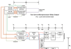
The information above is provided in “network snapshots” and “protection snapshots” in a cyclic update process with the agreed data exchange protocols. In the DGCC project, as shown in Figure 1, XML file-based interfaces for network and protection snapshots were used. Network and protection snapshots were used to update the network reference model with automated tools.
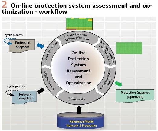
Figure 2 shows the DGCC workflow starts from a reference network model and continues by updating with network snapshots, updating with protection snapshots, and generating PSA results automatically. It also shows that optimization of protection settings and schemes should be done automatically in an adaptive protection system.
Siemens PTI used optimization routines for protection relay settings in the DGCC project. On the other side, Siemens PTI implemented pilot adaptive rules for setting optimization in the US project. These rules will be included in a “Business Rule Engine.” Adaptive rules are selected by authorized protection engineers.
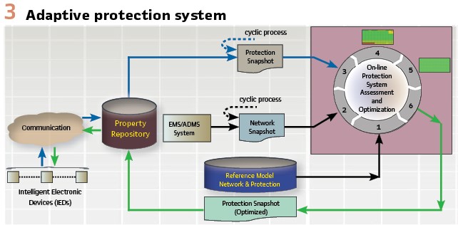
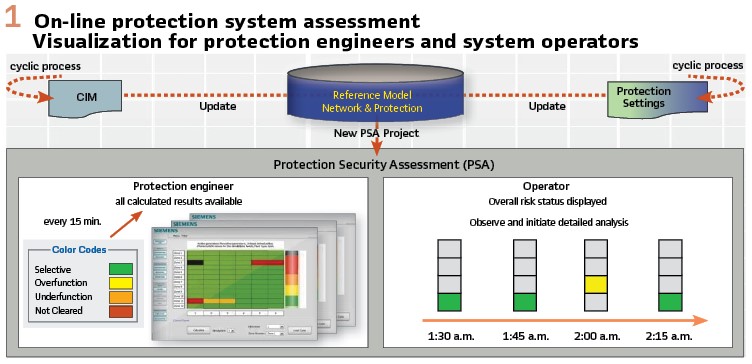
Above optimization routines or adaptive rules are designed to fix identified protection system weak points, such as miscoordination or not-cleared-fault problems. Mitigation of weak points is revalidated by using a PSA check. Then protection settings with optimized and validated settings/schemes are saved as an optimized protection snapshot as shown in Figure 2 and Figure 3.
Adaptation of Protection Device Parameters: Optimized and validated protection settings are stored in a protection repository and a new protection snapshot. Settings in the protection repository are vendor specific and not generic.
In addition, all protection devices with settings adaptation capability (i.e. IED’s) as well as those without adaptation capability (i.e. electromechanical and electronic, and digital relays) are stored in the protection repository.
IED’s parameters will be updated via a communication system. This part was not implemented in the DGCC project. Figure 2 and Figure 3 together present the main component of an Adaptive Protection System (APS). They also show workflow and data exchange among different components of protection assessment, protection optimization, and protection adaptation.
The proposed workflow is based on PSA of the entire distribution network, with a routine-based or rule-based optimization of protection parameters and adaptation of protection device parameters.
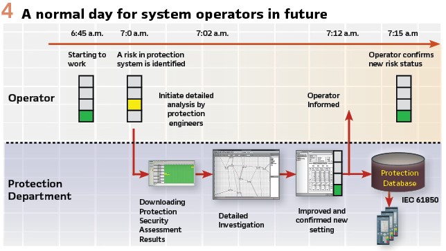
Figure 4 shows a normal day for system operators and protection engineers in future networks with high penetration of DERs.
Management, Modeling and Validation of Network Model
In order for the Adaptive Protection System (APS) to work correctly, it is essential to model electrical networks as accurately as possible.
This leads to the concept of network model management. How do we ensure that the model provided to the APS accurately represents the actual network? What is the process for updating the network model as the actual network changes due to switching operations or generation (DER) or load changes?
Project Network Modeling: In the US Project, network model management will be performed within a model management subsystem.
This subsystem will automatically recognize changes in the power system conditions and configurations, formulate the necessary feeder model, and provide the model to the APS for further processing.
The model management subsystem will perform the following tasks:
- Indicating whether the study is to be run in “real-time” with the present topology, “as-built” or “future planning” mode
- Calculating the source impedance at the distribution substation (feeder head)
- Developing a detailed model of the distribution feeder including cable and overhead line impedances, cable thermal damage data, load phasing, transformer impedance and winding configuration
- Determining feeder topology with information about switch and circuit breaker status
- Providing DER types (wind, PV, battery) generation status and dispatch level
- Providing load flow information to the APS
- Informing the APS about special feeder considerations such as high fire risk area data
For each feeder and its associated equipment such as cables, overhead lines, transformers, DERs, loads, etc., the model management subsystem needs to have accurate information about all the electrical parameters that may impact calculation of short-circuit currents.
Therefore, as a first step, the model of each feeder in its normal operating state has to be validated against actual field data, test reports, and other reference information for this feeder. Once this validation is completed and model inaccuracies are corrected, the model can be used for short-circuit and protection security assessment studies.
Project Network Model Validation: Validation and verification of electrical parameters of the model of distribution feeders against actual data is a key first step in short-circuit calculations and protection system studies. This process tends to be, for the most part, a manual process. It typically requires engineers to read test reports, line or cable maps, field data, and other data sources and to update the model. Sometimes, the data is incomplete or missing altogether. Therefore, the resulting model often is deficient compared to reality.
To check the effects of using an inaccurate model on the resulting short-circuit calculations, and subsequent impact on protection settings calculations, US based electric utility and Siemens performed a model degradation study. A distribution feeder was chosen as the test bed. The feeder model was then “pulled” from the utility’s tool, and modified to:
- Correct default values for conductors used in the utility’s model with accurate ones
- Update source impedances if necessary and match these with the utility’s approved values
- Check and update relay protection settings at the circuit breaker
- Verify feeder sectionalizing, including fusing and intelligent switch locations
These changes resulted in the “base case” model and are deemed to accurately represent the state of the feeder in the field. At this point, the “base case” was degraded by changing various parameters to represent inaccuracies between the model and actual field conditions in the feeder.
Model inaccuracies can result in the calculated short-circuit fault currents significantly differing from the actual fault currents. The adaptive calculation of protection settings, which is based on the calculated fault currents, could result in protective device settings that do not provide adequate protection.
The goal of the model degradation effort was to find out the extent to which the short-circuit fault currents deviate from the “base case,” as a result of varying the feeder parameters. Some of the electrical parameters that were varied include:
1) Unequal phase loading
2) Changes to DER generation levels
3) Changes to conductors representing discrepancy between an actual conductor in the field and in the model
4) Changes to source impedance data
For each such parameter being varied, short-circuit faults were applied at three different locations in the feeder model – the source, midpoint and end of line (farthest point on the feeder).
For each of these faults, the difference in fault current between the “base case” and the degraded model were recorded. In summary, the studies indicate the following:
- Online status of one large DER (20 MW) or multiple DERs in different locations with large total capacity (20 MW) has a significant impact (> 10%) on the short circuit duty. Also, the fault current at the source is reduced, which can have an impact on the sensitivity of the protection at the source
- Compared to one large DER near the feeder, multiple DERs in different locations with large total capacity have less impact on short circuit duty, especially for three phase faults
- When the feeder is modeled with a totally wrong conductor, the impact on short circuit duty is significant. The fault current at the source is significantly changed, which can have an impact on sensitivity of the protection at the source
- Equivalent source impedance (system short circuit MVA) has significant impact on short circuit duty. The largest impact is observed for faults at the source
- Other model degradation factors have less impact on fault duty at the feeder. These model degradation factors include load shifting to different phases, generation shifting to different phases, impedance of getaway conductor changing to higher resistance, transformer impedance and grounding status changing, and single-phase tap line conductor size reducing, etc.
While some level of inaccuracy is acceptable, it is important to ensure that the model represents the actual network as closely as possible. There must also be mechanisms and processes in place to ensure that changes and upgrades to the system are reflected in the model in a timely manner. The base case model is updated based on such mechanisms and processes.
Protection Model Management
Protection system topology and protection relay settings are added into the network base case model. At present, we build and validate protection system topology manually. Protection system elements like current transformers, voltage transformers, fuses, relays, IEDs, autoreclosers, etc. are added manually to the network base case model.
Protection assets will most probably be addressed in the CIM standard. It is also possible to build a protection system topology using customized or self-defined interfaces. Both ways provide solutions to create a protection system topology automatically.
As explained, protection engineers validate and release a base case model used for on-line protection security assessment. In the first step, the protection topology is added to the base case model. Protection topology refers to protection device locations with empty parameters and connection to breakers, current and voltage transformers. In the second step, the protection device parameters are added to the base case model.
An automated data-bridge tool maps the protection device parameters in both directions between each protection snapshot and the reference model in Figure 2. A unique ID is assigned to each protection device in the protection repository of Figure 3 and the corresponding protection device location in the base case model. The resulted model is called the reference model for network and protection assets.
Protection Modeling: The automated data-bridge between the protection setting database and the base case model generates all protection locations on the required breakers. Therefore, at least three different CIM IDs are necessary to get the right position of the protection device:
a) CIM ID of the operated circuit breaker
b) CIM ID of the terminal where the current transformer is located
c) CIM ID of the connectivity node where the potential transformer is located
Based on these three IDs, all protection locations can be added to the network model. Depending on the protection device, one protection location can hold multiple protection functions with multiple steps inside these functions. These functions and steps will be added based on the protection database.
After adding all protection devices to the network, a working model is ready for further usage. To verify the required simulation functionality, the protection models should be validated.
Protection Model Validation: To validate the resulted protection topology automatically, a rule-based protection simulation can be used. The clearing time of all protection functions within one device are known through the protection database. A fault simulation close to each protection device can be used to check this clearing time. If the protection device issues a trip for all required fault types, the protection models were successfully validated. This validation should only verify that all protection devices are working and tripping the right circuit breaker. Validating the protection settings is not part of this step and will be done through Protection Security Assessment (PSA).
Conclusion
A validated model for network and protection system is the main requirement for an adaptive protection system. The following workflow has been researched in the DGCC project to build a pilot adaptive protection system. These steps in the workflow are also compatible with the US based utility’s envision and they are applicable to other electric utilities:
a) DERs’ operation status is collected through a communication network in a long-term view. In short-term, above information may be collected using available utilities’ maintenance reporting system or they can be defined in customer contracts
b) DERs’ generation and consumption are modeled in power utilities’ network models for load flow and short-circuit calculations. This model covers time dependency profile of customers’ load and DERs’ generation and consumption
c) All possible what-if short-circuit fault scenarios are generated automatically on a system wide basis. Protection device responses to each fault scenario are simulated automatically
d) A stepped event short-circuit analysis together with protection simulation are conducted for each fault scenario from fault inception to fault clearing
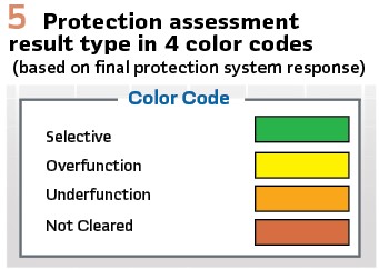
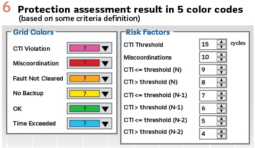
e) Responses of protection devices are assessed automatically for all fault scenarios. Each fault scenario is ranked for protection engineers to understand the risk very fast. For example, by defining different risk types with color codes in Figure 5 and Figure 6
f) Protection security assessment (PSA) results of distribution system protection devices are ranked for system operators as coordinated (or selective), and not coordinated (e.g. in three different types: Over-function, Under-function, or Not-Cleared-Fault)
g) PSA results for the present operating condition are reported to distribution system operators and protection department engineers
h) Authorized protection engineers define adaptive coordination rules/routines for application on identified miscoordinations in the PSA results. Resulted optimized protection settings are reported to protection engineers
i) A successful application of the applied adaptive rule/routines must be validated by repeating items (e) and (f)
j) A communication network transfers optimized protection settings to adaptive IEDs and auto-reclosers. PSA results and applied adaptive rules can also indicate whether a network fuse rating/type should be revised
In addition, PSA results can also be used to predict a protection system’s performance trend beyond the present operating condition. A proper settings schedule can be prepared when a load/generation forecast for DERs and consumer loads is available.
Biographies:

Reza Ganjavi is a senior key expert within Siemens for protection system design, coordination, and functional security assessment. He joined Siemens PTI in Germany in 2001, working in the field of protective relaying. He has 24 years’ experience in power system consulting and development of innovative software solutions with a focus on protection studies and study management for customers in T&D, power generation, industry, and electric rail sectors. He has a Ph.D. degree in application of expert systems for power system protection from the Otto-von-Guericke University of Magdeburg in Germany. He is a senior member of the IEEE.

Martin Mangold received the B.Sc. degree at the University of Erlangen, in 2011, and the M.Sc. degree at the University of Erlangen, Department of Electrical Engineering, in 2013. He joined Siemens in Germany in 2013. He is currently working as a product manager for network model management solutions with Siemens. He is a Senior Key Expert within Siemens for network modelling solutions.

Rainer Krebs (S.M. IEEE, member CIGRE, VDE and IEC) studied Electrical Engineering at the Friedrich-Alexander University Erlangen, Germany. In 1990 he got his PHD from the same University and started with Siemens AG. He worked on numerous national and international technical and scientific projects. He is “Principal Expert” and head of the Siemens PTI department “Protection, Operation and Control System Studies”. He is author/co-author of more than 240 scientific papers and inventor with more than 10 patents. Since 2008 he is honorary professor at the Otto-von-Guericke University Magdeburg and since 2016 Member of the advisory board. In 2018 he got the “Siemens Top-Innovator” Award.

Ashok Gopalakrishnan has over 22 years of experience in power system analysis, with a focus on protection and control consulting services. He is presently the engineering director of the PSS®CAPE software team, with overall business responsibility for the product. At Siemens, he has also led the US-based Protection and Control consulting group. Prior to joining Siemens in 2018, Dr. Gopalakrishnan held positions of increasing responsibility over four years at Quanta Technology, LLC. His contributions at Quanta included providing technical leadership and project management for several protection and control projects, as well as serving as a key account advisor for large investor-owned utilities. From 1999 to 2014, Dr. Gopalakrishnan was with Electrocon International, Inc. (now part of Siemens) and was a key member of the engineering team that developed the PSS®CAPE software. He is a senior member of the IEEE.

Yaming Zhu (Ph.D.) received the B.S. from Tsinghua University, P.R. China, in 1989, the M.S. from the Graduate School of Nanjing Automation Research Institute, P.R. China, in 1992, and the Ph.D. from Washington State University, Pullman, WA in 2002, all in Electrical Engineering. He is currently a Senior Key Expert and Technical Manager in the Power System Consulting department at Siemens PTI. He has managed various transmission planning studies, NERC Compliance studies, and protection coordination studies.

Wayne Dias has over 15 years of electric power utility experience. He oversees all technical, business development and marketing strategies of Grid Simulation products across the US and drives new client markets and develops strategies. He is hands-on with resolving complex customer requests and serves as a liaison to the Global Software team and developers. Prior to Siemens PTI, Wayne was at California ISO (Power Balancing Authority for PG&E, SCE and SDGE) where he served as a Real Time Generation Dispatcher directing and coordinating the economic and reliability operation of the CAISO bulk power electric system. He leads all technical software demonstration and workshops in the US market. Prior to California ISO, Wayne worked at Southern California Edison (SCE). He received his B.Sc. degree Electrical Engineering (2009), and his MBA degree (2016) at California State University, Sacramento, CA, USA.