by M. Mohemmed, Scottish & Southern Electricity Networks (SSEN), UK, P. Orr, S. Blair, N. Gordon, I. Mckeeman, Synaptec, UK, A. Mohamed, ScottishPower Renewables, UK, and A. Bonetti, Megger, Sweden
New grid connections for low-carbon technologies can lead to costly engineering work to install and protect the resulting complex, multi-ended circuit. Circuit protection for multi-ended feeders is conventionally implemented via line differential or distance protection. However, each option has drawbacks. Line differential protection requires a protection relay at each feeder-end with reliable alignment of current measurements, plus a robust telecommunications infrastructure. This duplication of equipment at each line end results in significant total costs and, in older substations, space constraints can be a limiting factor.
Operators seeking to protect multi-ended circuits are therefore often required to utilize distance protection, resulting in complex setting calculations, reduced resilience (due to the under-reaching effects caused by fault infeeds from teed circuits), and increased operation time of the scheme.
SSEN Transmission and Synaptec have collaborated in the UK to demonstrate a robust solution to these challenges using passive, distributed sensing, with the goal to demonstrate reduced overall equipment costs, reduced infrastructure requirements, and faster installation of the protection scheme.
By enabling line differential protection to be deployed on multi-ended circuits, the approach offers improved protection accuracy in locations where distance protection would previously have been required due to space, cost, or telecommunications bandwidth constraints.
Passive sensor technologies address the challenges associated with conventional approaches to multi-ended circuit protection. This article describes a solution which has been installed in a 132 kV system in the UK and provides a full multi-ended differential protection scheme, but without requiring IEDs or any active electronics in all substations. Standard CTs are passively coupled to an optical fiber and a central Interrogator unit is able to access current measurements from both the local substation and a remote substation 30 km away (with distances of approximately 60 km also being possible,) and publish time synchronized IEC 61850-9-2 LE Sampled Value data streams. This approach offers a cost-effective solution for protecting circuits, particularly for complex arrangements with multiple ends and space restrictions.
This project represents the first time that passive distributed sensors have been deployed for multi-ended circuit protection, and therefore this capability is likely to be of interest to protection engineers faced with delivering affordable and resilient protection of multi-ended transmission circuits or similarly challenging networks that would benefit from multi-zone differential protection capability.
Challenges Protecting Complex Multi-Ended Circuits
One of the major challenges in smart grid applications is how to protect the system in a cost-effective way. Often it is possible to use proven protection solutions and technologies which are commonly applied in high voltage power networks, but these solutions are typically also very expensive. Figure 1 illustrates a conventional multi-ended protection scheme using differential protection, where three substations need to communicate with each other. The disadvantages of this approach are:
- To achieve unit protection, protection IEDs are required at all terminals, with the associated capex costs, integration testing, and maintenance costs. Being able to reduce the number of devices to manage is highly desirable
- Requires complex telecoms infrastructure for continuous comparison of current measurements. While this can be achieved with SDH/PDH- and MPLS-based networks, there is complexity in validating the performance for protection requirements (i.e., low latency and jitter) under all conditions
- Requires robust GNSS access at every location for measurement synchronization. Alternatively, synchronization using the “ping-pong” method requires a stable communications network with low jitter and asymmetry
- There may be limitations on space and the available telecommunications data bandwidth in remote substations, meaning that upgrades are not feasible
- Compatibility and interoperability with other IEC 61850 devices in the long term is not a given, as existing line protection IEDs will typically use IEEE C37.94 interfaces (or proprietary equivalents). This can be exacerbated by the potential for mismatch of firmware versions for IEDs communicating over a wide-area network
- Distance protection offers an alternative, but has significant limitations, such as over- and under-reach caused by fault infeeds from teed circuits. It is also challenging to design and validate distance protection schemes under all possible conditions
- Depending on the operator’s policies, it may be required or desirable to secure the data streams between substations with encryption and/or authentication. This can add significant complexity, such as requiring the use of Routable-SV and associated infrastructure for cryptographic key management
Passive Sensing of Remote Locations
Distributed Electrical Sensing (DES) is a technology platform which allows measured values from over 30 current transformers to be acquired passively using a single optical fiber core (e.g., an available OPGW core) over distances of up to 60 km. These measurements can then be utilized as part of centralized protection schemes or communicated to conventional protection devices via IEC 61850-9-2/61869-9. This method eliminates the need of having multiple protection relays, complex time synchronization systems to align current measurement data, and telecommunications equipment at each line end.
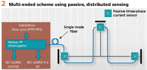
Figure 2 illustrates a three-ended scheme using distributed sensing. Passive current sensors are installed at each terminal, and existing CTs can be interfaced via a Secondary Connected Module (SCM) (see Figure 4). These sensors are coupled to existing single-mode fiber and the Interrogator. This results in centralized publishing of protection-class measurements to local protection IEDs using IEC 61850-9-2 Sampled Values (SV). All measurements are synchronized to a global reference using IEC 61850-9-3 PTP (the slight sampling delay due to the speed of light in fiber is automatically compensated). A useful benefit is that global time synchronization (and provisioning of a PTP clock) is not required to provide protection functionality, because the current measurements are inherently synchronized relative to each other – therefore the system is resilient if the PTP source fails or is not available.
There are several technical benefits arising from this centralized, single-ended approach to line differential protection:
- Readily supports new grid connections with the potential to reduce civil engineering works by avoiding the need for new equipment housings
- Faster-acting multi-ended differential protection, due to elimination of the typical wide-area communications delay of 2-6 ms, and elimination of other complications such as asymmetrical delay
- Removal of vulnerability to loss-of-sync errors between terminals. In conventional schemes, this would cause incorrect tripping or require the protection function to be blocked
- Enables rapid and accurate post-event response – all measurements are accurately time synchronized and published in a standard format (IEC 61850-9-2/IEC 61869-9) which facilitates examining of fault records for complex events
- Publishing synchronized waveform data to the process bus permits further analysis from the same data used by the protection scheme, including for power quality and transient analysis. This can lead to condition monitoring insights resulting from the same infrastructure
- The measurement information is inherently secure as it is transferred via modulated wavelengths of light. This cannot be eavesdropped or interfered with, except by breaking the fiber, which is instantaneously detected by the Interrogator
Implementation and Live
Trial on 132 kV Circuit
The passive sensing solution has been implemented and tested using real-time simulation of two- and three-ended schemes during factory acceptance tests (FATs), and a live trial of a two-end scheme on a 132 kV circuit in the SSEN Transmission network in Scotland has been deployed.
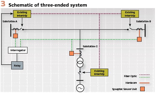
Figure 3 shows the single-line diagram of a simulated three-ended implementation. The scheme consists of three main hardware components:
1. Interrogator: rack-mount device, located in the substation, for collating and publishing measurements from arrays of passive fiber optic sensors
2. Secondary Connected Modules (SCMs): Passive fiber optic current sensor, connecting to an industry-standard solid or split-core current transformer (CT), insulated as required for the voltage level and environment
3. External protection relays to subscribe to SV data published by the Interrogator and perform the line protection function. Alternatively, the Interrogator can implement protection onboard, to further reduce the number of devices required (including Ethernet switches) and trip times
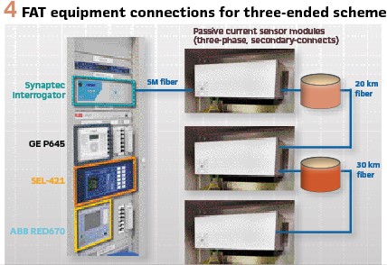
The Interrogator interfaces with the sensors at feeder terminals using one core of the existing single mode fibers in the Optical Ground Wire (OPGW). The SCMs are spliced into the existing fiber network at the splice trays present at each feeder end substation. Figure 4 illustrates how the equipment is connected. Note that reels of fiber are used to emulate the required distances to ensure that the testing is realistic. Protection relays from three different vendors were used to ensure full interoperability of the solution.
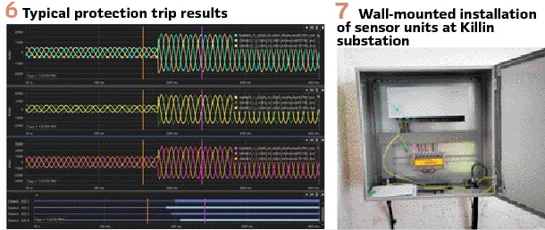
Figure 6 provides an example of a three-phase fault simulated during the FAT process, and the resulting trip signals from external protection relays. In summary:
- Fault scenarios are generated and injected onto all three passive sensor modules synchronously
- Three relays receive SV and all trip consistently in <20 ms following fault inception
- System stability was also proven, as external faults result in no false trip from any relay
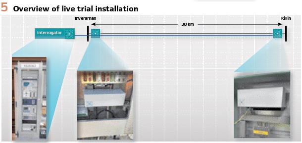
A full two-ended system has been installed on an SSEN Transmission 132 kV circuit during Summer 2021 for operational testing. The protection scheme performance will be compared with the existing conventional system over two winter periods, to comprehensively validate the solution in realistic conditions. Figure 5 illustrates the scheme, which operates between two substations in Scotland that are approximately 30 km apart.
The sensor units have been installed in an HV compound marshalling kiosk at Inverarnan substation during Summer 2021. At the remote end at Killin substation, the sensor units were installed in a wall-box within the telecoms room which is temperature controlled. The Figure on page 38 and Figure 7, show these installations in more detail. This shows that the passive sensors are suitable for diverse installation locations and can be designed for a wide range of temperature and IP requirements. During the trial, the performance of each sensor installation type will be monitored.
There is also an important safety benefit from only installing passive equipment in HV compounds or switchyards, as all active electronic equipment, which will require configuration and maintenance, can be located elsewhere (away from HV equipment), with only a fiber optic cable required to the HV areas. In contrast, a Stand-Alone Merging Unit (SAMU) IED must be located either near to the CTs in the HV compound, or long copper leads are required from the CTs into the IED room. The passive sensing approach avoids both of these undesirable approaches. Furthermore, being able to secondary-connect to existing CTs provides a retrofit option for “brownfield site” installations.
Lessons Learned
The core function of the system has been realized and installed, leading to the world’s first demonstration of a single-ended unit protection scheme over 30 km (with a 50 km system also undergoing factory acceptance testing).
However, several factors have been observed during the project which can lead to refinement in the future:
- The passive sensing approach does not map directly to existing standards for Low Power Instrument Transformers (LPIT) and SAMUs, so care must be taken in how these standards are applied
- It is important to specify and understand the system performance of the full range of load and fault currents. During the implementation of the system, the Interrogator was required to be recalibrated and the CT ratio changed from 1200/1 to 600/1 to be more accurate at lower load currents. This resulted in improved signal acquisition of the fundamental component and reduced noise and harmonic distortion
- Interpretations of the IEC 61850 standards can lead to variations in implementations between vendors. For example, the behavior of an external protection relay during degraded conditions, such as loss of global time synchronization, should be specified and tested
- Significant time is also required to set up devices from various vendors for interoperation. Typically, each vendor will have different configuration tools, SV settings, VLAN settings, and support for different PTP versions
- It is important to provide time for testing interoperability, as this requires coordination between multiple parties to resolve issues
- New tools and skills are required – spanning protection, telecoms, IEC 61850, and the practicalities of using optical fibers. Industry-wide training at early stages is essential to become acquainted with the technologies involved. Collaboration between the vendors and contractors involved in the trial project was important to identify and resolve technical issues
Business Case and Future Applications
A comprehensive commercial evaluation of the passive sensing and protection system has been performed, including capital equipment cost reductions, operational cost reductions, health and safety benefits, system resilience improvements, and environmental impact reductions.
The approach summarized in this article has the potential to save significant capital expenditure, compared to conventional approaches to multi-ended circuit protection. This is due to requiring less secondary equipment, the reduced substation footprint, minimizing civil engineering work, reduced copper wiring, and the ability to use existing standard optical fibers available in OPGW.
There are also other important factors which reduce operational costs and enable improved functionality over conventional protection schemes:
- Faster and safer installation and maintenance with optical isolation on secondary side
- Fewer IEDs to test, commission, and maintain over time – also resulting in a lower carbon footprint
- Faster protection by eliminating asymmetrical and wide area communications delays
- Eliminates the need for dedicated telecoms channels and related equipment between feeder ends (with the exception of the fiber required for the passive sensor network). For conventional protection of three-ended circuits, a minimum of two telecoms channels are required whereas the solution in this paper only requires a single fiber core
- Continuous synchronized waveform streaming enables power quality and transient analysis
- Provides readiness for incoming IEC 61869 standards from IEC TC 38
- Facilitates new connections, particularly for low-carbon generation and other technologies
Trial projects are important building blocks for delivering digital substations and related technologies which are the future for many utilities, including SSEN Transmission. This project successfully demonstrated single-ended differential protection over 30 km on a 132 kV circuit. The performance of the installed system will be reviewed periodically, and data will be captured to establish internal standards and specifications for future projects.
The approach is standards-based and compatible with multi-vendor relays. Local and remote measurements are delivered as synchronized SV streams within 1 ms, without wide-area communications networking. This offers the opportunity to deploy unit protection in areas where distance protection previously had been the only option.
Compared to conventional approaches, passive sensing leads to greatly reduced capex, fewer devices to install, test, and maintain, and improved safety (due to no CT wiring in the protection panel for safe maintenance.)
Biographies:
Mohseen Mohemmed is an Engineering Manager working in the Transmission Policy and Standards Team of Scottish & Southern Electricity Networks (SSEN) providing technical leadership on protection & control aspects for its full digital substation development project (TReNDs). Mohseen graduated from Robert Gordon University, Aberdeen in 2002, starting work with Balfour Beatty Engineering Services where he developed solutions for all transmission voltages before joining SSEN Transmission in 2012. He is the UK regular member for CIGRE WG B5.74.
Philip Orr is the founder and managing director of Synaptec, a specialist power systems instrumentation company based in Glasgow. Prior to founding Synaptec in 2015, Philip was Scotland’s first Royal Academy of Engineering Enterprise Fellow, and a researcher at the University of Strathclyde. His doctoral work focused on photonic instrumentation for fusion reactors, and he is the recipient of several engineering prizes including the Sir William Siemens Medal and the EPSRC Doctoral Prize. He is the author of over 40 publications in the field of instrumentation and co-inventor of Synaptec’s core patents.
Steven Blair is the Head of Power System Technologies at Synaptec, where he leads the software and data analytics team. He holds a PhD in Electronic & Electrical Engineering and an MEng in Computer & Electronic Systems from the University of Strathclyde, UK. He has been an academic at the University of Strathclyde, including holding the Nokia lectureship position. He is very experienced in power system protection, power quality, data analysis, and real-time systems. Steven is a member of IEC TC57 WG 10, CIGRE Joint Working Group C4/C2.62/IEEE, and IEEE WG PSCC P10.
Neil Gordon is Head of Sensor Technologies at Synaptec, overseeing the development of sensors and associated systems. He concluded his award-winning doctoral work in 2015 on photonic engineering as part of the international team that successfully detected gravitational waves for the first time and joined Synaptec shortly afterwards. Neil leads our team of experienced engineers and physicists in the design and manufacture of our sensing technologies.
Iain Mckeeman is a Senior Sensor Technologies Engineer at Synaptec. He was awarded the MPhys with Photonics from the University of Southampton in 2012. He then undertook an Engineering Doctorate in Optics and Photonics Technologies, publishing his thesis in the area of fiber-optic instrumentation of nuclear reactor containment structures. Following his doctorate, Iain was seconded to Synaptec throughout 2018 and joined the company full-time as Systems Engineer shortly thereafter, bringing with him his knowledge on fiber-optic instrumentation and mechanical sensing.
Ahmed Mohamed is a Senior Protection and Control Engineer at ScottishPower Renewables. He graduated as an Electrical Power Engineer from Helwan University, Egypt in 2005. He has been working as a Protection and Control Engineer since 2006. He started in Egyptian Electricity Transmission Company (EETC) then moved in 2008 to Dubai Electricity and Water Authority (DEWA). From 2013-2020, he worked at Scottish and Southern Energy Network (SSEN), Glasgow, UK. He is a member of the IEC TC 95/WG2.
Andrea Bonetti is a Senior Specialist at Megger Sweden AB and specializes in power system protection and IEC 61850 applications. He is a member of IEC TC95/MT 4 and TC 95/WG2. He holds a patent in IEC 61850 testing tools and algorithms and has received the IEC 1906 Award in 2013 which recognizes his exceptional achievements and expertise. He has been a guest lecturer at Royal Institute of Technology at Stockholm (KTH) on IEC 61850 for substation automation applications since 2008. He holds a Master of Science degree in electrotechnical engineering from Sapienza University at Rome.
Differential Protection of Multi-Ended Transmission Circuits using Passive Distributed Sensor
by M. Mohemmed, Scottish & Southern Electricity Networks (SSEN), UK, P. Orr, S. Blair, N. Gordon, I. Mckeeman, Synaptec, UK, A. Mohamed, ScottishPower Renewables, UK, and A. Bonetti, Megger, Sweden
New grid connections for low-carbon technologies can lead to costly engineering work to install and protect the resulting complex, multi-ended circuit. Circuit protection for multi-ended feeders is conventionally implemented via line differential or distance protection. However, each option has drawbacks. Line differential protection requires a protection relay at each feeder-end with reliable alignment of current measurements, plus a robust telecommunications infrastructure. This duplication of equipment at each line end results in significant total costs and, in older substations, space constraints can be a limiting factor.
Operators seeking to protect multi-ended circuits are therefore often required to utilize distance protection, resulting in complex setting calculations, reduced resilience (due to the under-reaching effects caused by fault infeeds from teed circuits), and increased operation time of the scheme.
SSEN Transmission and Synaptec have collaborated in the UK to demonstrate a robust solution to these challenges using passive, distributed sensing, with the goal to demonstrate reduced overall equipment costs, reduced infrastructure requirements, and faster installation of the protection scheme.
By enabling line differential protection to be deployed on multi-ended circuits, the approach offers improved protection accuracy in locations where distance protection would previously have been required due to space, cost, or telecommunications bandwidth constraints.
Passive sensor technologies address the challenges associated with conventional approaches to multi-ended circuit protection. This article describes a solution which has been installed in a 132 kV system in the UK and provides a full multi-ended differential protection scheme, but without requiring IEDs or any active electronics in all substations. Standard CTs are passively coupled to an optical fiber and a central Interrogator unit is able to access current measurements from both the local substation and a remote substation 30 km away (with distances of approximately 60 km also being possible,) and publish time synchronized IEC 61850-9-2 LE Sampled Value data streams. This approach offers a cost-effective solution for protecting circuits, particularly for complex arrangements with multiple ends and space restrictions.
This project represents the first time that passive distributed sensors have been deployed for multi-ended circuit protection, and therefore this capability is likely to be of interest to protection engineers faced with delivering affordable and resilient protection of multi-ended transmission circuits or similarly challenging networks that would benefit from multi-zone differential protection capability.
Challenges Protecting Complex Multi-Ended Circuits
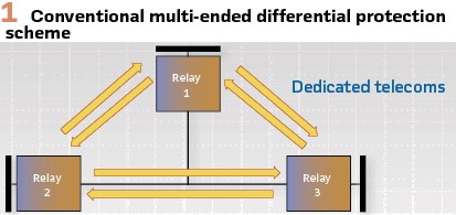
One of the major challenges in smart grid applications is how to protect the system in a cost-effective way. Often it is possible to use proven protection solutions and technologies which are commonly applied in high voltage power networks, but these solutions are typically also very expensive. Figure 1 illustrates a conventional multi-ended protection scheme using differential protection, where three substations need to communicate with each other. The disadvantages of this approach are:
- To achieve unit protection, protection IEDs are required at all terminals, with the associated capex costs, integration testing, and maintenance costs. Being able to reduce the number of devices to manage is highly desirable
- Requires complex telecoms infrastructure for continuous comparison of current measurements. While this can be achieved with SDH/PDH- and MPLS-based networks, there is complexity in validating the performance for protection requirements (i.e., low latency and jitter) under all conditions
- Requires robust GNSS access at every location for measurement synchronization. Alternatively, synchronization using the “ping-pong” method requires a stable communications network with low jitter and asymmetry
- There may be limitations on space and the available telecommunications data bandwidth in remote substations, meaning that upgrades are not feasible
- Compatibility and interoperability with other IEC 61850 devices in the long term is not a given, as existing line protection IEDs will typically use IEEE C37.94 interfaces (or proprietary equivalents). This can be exacerbated by the potential for mismatch of firmware versions for IEDs communicating over a wide-area network
- Distance protection offers an alternative, but has significant limitations, such as over- and under-reach caused by fault infeeds from teed circuits. It is also challenging to design and validate distance protection schemes under all possible conditions
- Depending on the operator’s policies, it may be required or desirable to secure the data streams between substations with encryption and/or authentication. This can add significant complexity, such as requiring the use of Routable-SV and associated infrastructure for cryptographic key management
Passive Sensing of Remote Locations
Distributed Electrical Sensing (DES) is a technology platform which allows measured values from over 30 current transformers to be acquired passively using a single optical fiber core (e.g., an available OPGW core) over distances of up to 60 km. These measurements can then be utilized as part of centralized protection schemes or communicated to conventional protection devices via IEC 61850-9-2/61869-9. This method eliminates the need of having multiple protection relays, complex time synchronization systems to align current measurement data, and telecommunications equipment at each line end.
Figure 2 illustrates a three-ended scheme using distributed sensing. Passive current sensors are installed at each terminal, and existing CTs can be interfaced via a Secondary Connected Module (SCM) (see Figure 4). These sensors are coupled to existing single-mode fiber and the Interrogator. This results in centralized publishing of protection-class measurements to local protection IEDs using IEC 61850-9-2 Sampled Values (SV). All measurements are synchronized to a global reference using IEC 61850-9-3 PTP (the slight sampling delay due to the speed of light in fiber is automatically compensated). A useful benefit is that global time synchronization (and provisioning of a PTP clock) is not required to provide protection functionality, because the current measurements are inherently synchronized relative to each other – therefore the system is resilient if the PTP source fails or is not available.
There are several technical benefits arising from this centralized, single-ended approach to line differential protection:
- Readily supports new grid connections with the potential to reduce civil engineering works by avoiding the need for new equipment housings
- Faster-acting multi-ended differential protection, due to elimination of the typical wide-area communications delay of 2-6 ms, and elimination of other complications such as asymmetrical delay
- Removal of vulnerability to loss-of-sync errors between terminals. In conventional schemes, this would cause incorrect tripping or require the protection function to be blocked
- Enables rapid and accurate post-event response – all measurements are accurately time synchronized and published in a standard format (IEC 61850-9-2/IEC 61869-9) which facilitates examining of fault records for complex events
- Publishing synchronized waveform data to the process bus permits further analysis from the same data used by the protection scheme, including for power quality and transient analysis. This can lead to condition monitoring insights resulting from the same infrastructure
- The measurement information is inherently secure as it is transferred via modulated wavelengths of light. This cannot be eavesdropped or interfered with, except by breaking the fiber, which is instantaneously detected by the Interrogator
Implementation and Live
Trial on 132 kV Circuit
The passive sensing solution has been implemented and tested using real-time simulation of two- and three-ended schemes during factory acceptance tests (FATs), and a live trial of a two-end scheme on a 132 kV circuit in the SSEN Transmission network in Scotland has been deployed.
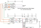
Figure 3 shows the single-line diagram of a simulated three-ended implementation. The scheme consists of three main hardware components:
1. Interrogator: rack-mount device, located in the substation, for collating and publishing measurements from arrays of passive fiber optic sensors
2. Secondary Connected Modules (SCMs): Passive fiber optic current sensor, connecting to an industry-standard solid or split-core current transformer (CT), insulated as required for the voltage level and environment
3. External protection relays to subscribe to SV data published by the Interrogator and perform the line protection function. Alternatively, the Interrogator can implement protection onboard, to further reduce the number of devices required (including Ethernet switches) and trip times
The Interrogator interfaces with the sensors at feeder terminals using one core of the existing single mode fibers in the Optical Ground Wire (OPGW). The SCMs are spliced into the existing fiber network at the splice trays present at each feeder end substation. Figure 4 illustrates how the equipment is connected. Note that reels of fiber are used to emulate the required distances to ensure that the testing is realistic. Protection relays from three different vendors were used to ensure full interoperability of the solution.
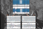
Figure 6 provides an example of a three-phase fault simulated during the FAT process, and the resulting trip signals from external protection relays. In summary:
- Fault scenarios are generated and injected onto all three passive sensor modules synchronously
- Three relays receive SV and all trip consistently in <20 ms following fault inception
- System stability was also proven, as external faults result in no false trip from any relay
A full two-ended system has been installed on an SSEN Transmission 132 kV circuit during Summer 2021 for operational testing. The protection scheme performance will be compared with the existing conventional system over two winter periods, to comprehensively validate the solution in realistic conditions. Figure 5 illustrates the scheme, which operates between two substations in Scotland that are approximately 30 km apart.
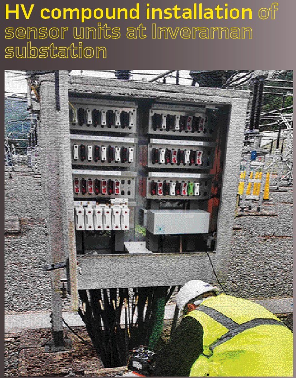
The sensor units have been installed in an HV compound marshalling kiosk at Inverarnan substation during Summer 2021. At the remote end at Killin substation, the sensor units were installed in a wall-box within the telecoms room which is temperature controlled. The Figure on page 38 and Figure 7, show these installations in more detail. This shows that the passive sensors are suitable for diverse installation locations and can be designed for a wide range of temperature and IP requirements. During the trial, the performance of each sensor installation type will be monitored.
There is also an important safety benefit from only installing passive equipment in HV compounds or switchyards, as all active electronic equipment, which will require configuration and maintenance, can be located elsewhere (away from HV equipment), with only a fiber optic cable required to the HV areas. In contrast, a Stand-Alone Merging Unit (SAMU) IED must be located either near to the CTs in the HV compound, or long copper leads are required from the CTs into the IED room. The passive sensing approach avoids both of these undesirable approaches. Furthermore, being able to secondary-connect to existing CTs provides a retrofit option for “brownfield site” installations.
Lessons Learned
The core function of the system has been realized and installed, leading to the world’s first demonstration of a single-ended unit protection scheme over 30 km (with a 50 km system also undergoing factory acceptance testing).
However, several factors have been observed during the project which can lead to refinement in the future:
- The passive sensing approach does not map directly to existing standards for Low Power Instrument Transformers (LPIT) and SAMUs, so care must be taken in how these standards are applied
- It is important to specify and understand the system performance of the full range of load and fault currents. During the implementation of the system, the Interrogator was required to be recalibrated and the CT ratio changed from 1200/1 to 600/1 to be more accurate at lower load currents. This resulted in improved signal acquisition of the fundamental component and reduced noise and harmonic distortion
- Interpretations of the IEC 61850 standards can lead to variations in implementations between vendors. For example, the behavior of an external protection relay during degraded conditions, such as loss of global time synchronization, should be specified and tested
- Significant time is also required to set up devices from various vendors for interoperation. Typically, each vendor will have different configuration tools, SV settings, VLAN settings, and support for different PTP versions
- It is important to provide time for testing interoperability, as this requires coordination between multiple parties to resolve issues
- New tools and skills are required – spanning protection, telecoms, IEC 61850, and the practicalities of using optical fibers. Industry-wide training at early stages is essential to become acquainted with the technologies involved. Collaboration between the vendors and contractors involved in the trial project was important to identify and resolve technical issues
Business Case and Future Applications
A comprehensive commercial evaluation of the passive sensing and protection system has been performed, including capital equipment cost reductions, operational cost reductions, health and safety benefits, system resilience improvements, and environmental impact reductions.
The approach summarized in this article has the potential to save significant capital expenditure, compared to conventional approaches to multi-ended circuit protection. This is due to requiring less secondary equipment, the reduced substation footprint, minimizing civil engineering work, reduced copper wiring, and the ability to use existing standard optical fibers available in OPGW.
There are also other important factors which reduce operational costs and enable improved functionality over conventional protection schemes:
- Faster and safer installation and maintenance with optical isolation on secondary side
- Fewer IEDs to test, commission, and maintain over time – also resulting in a lower carbon footprint
- Faster protection by eliminating asymmetrical and wide area communications delays
- Eliminates the need for dedicated telecoms channels and related equipment between feeder ends (with the exception of the fiber required for the passive sensor network). For conventional protection of three-ended circuits, a minimum of two telecoms channels are required whereas the solution in this paper only requires a single fiber core
- Continuous synchronized waveform streaming enables power quality and transient analysis
- Provides readiness for incoming IEC 61869 standards from IEC TC 38
- Facilitates new connections, particularly for low-carbon generation and other technologies
Trial projects are important building blocks for delivering digital substations and related technologies which are the future for many utilities, including SSEN Transmission. This project successfully demonstrated single-ended differential protection over 30 km on a 132 kV circuit. The performance of the installed system will be reviewed periodically, and data will be captured to establish internal standards and specifications for future projects.
The approach is standards-based and compatible with multi-vendor relays. Local and remote measurements are delivered as synchronized SV streams within 1 ms, without wide-area communications networking. This offers the opportunity to deploy unit protection in areas where distance protection previously had been the only option.
Compared to conventional approaches, passive sensing leads to greatly reduced capex, fewer devices to install, test, and maintain, and improved safety (due to no CT wiring in the protection panel for safe maintenance.)
Biographies:

Mohseen Mohemmed is an Engineering Manager working in the Transmission Policy and Standards Team of Scottish & Southern Electricity Networks (SSEN) providing technical leadership on protection & control aspects for its full digital substation development project (TReNDs). Mohseen graduated from Robert Gordon University, Aberdeen in 2002, starting work with Balfour Beatty Engineering Services where he developed solutions for all transmission voltages before joining SSEN Transmission in 2012. He is the UK regular member for CIGRE WG B5.74.

Philip Orr is the founder and managing director of Synaptec, a specialist power systems instrumentation company based in Glasgow. Prior to founding Synaptec in 2015, Philip was Scotland’s first Royal Academy of Engineering Enterprise Fellow, and a researcher at the University of Strathclyde. His doctoral work focused on photonic instrumentation for fusion reactors, and he is the recipient of several engineering prizes including the Sir William Siemens Medal and the EPSRC Doctoral Prize. He is the author of over 40 publications in the field of instrumentation and co-inventor of Synaptec’s core patents.

Steven Blair is the Head of Power System Technologies at Synaptec, where he leads the software and data analytics team. He holds a PhD in Electronic & Electrical Engineering and an MEng in Computer & Electronic Systems from the University of Strathclyde, UK. He has been an academic at the University of Strathclyde, including holding the Nokia lectureship position. He is very experienced in power system protection, power quality, data analysis, and real-time systems. Steven is a member of IEC TC57 WG 10, CIGRE Joint Working Group C4/C2.62/IEEE, and IEEE WG PSCC P10.

Neil Gordon is Head of Sensor Technologies at Synaptec, overseeing the development of sensors and associated systems. He concluded his award-winning doctoral work in 2015 on photonic engineering as part of the international team that successfully detected gravitational waves for the first time and joined Synaptec shortly afterwards. Neil leads our team of experienced engineers and physicists in the design and manufacture of our sensing technologies.

Iain Mckeeman is a Senior Sensor Technologies Engineer at Synaptec. He was awarded the MPhys with Photonics from the University of Southampton in 2012. He then undertook an Engineering Doctorate in Optics and Photonics Technologies, publishing his thesis in the area of fiber-optic instrumentation of nuclear reactor containment structures. Following his doctorate, Iain was seconded to Synaptec throughout 2018 and joined the company full-time as Systems Engineer shortly thereafter, bringing with him his knowledge on fiber-optic instrumentation and mechanical sensing.

Ahmed Mohamed is a Senior Protection and Control Engineer at ScottishPower Renewables. He graduated as an Electrical Power Engineer from Helwan University, Egypt in 2005. He has been working as a Protection and Control Engineer since 2006. He started in Egyptian Electricity Transmission Company (EETC) then moved in 2008 to Dubai Electricity and Water Authority (DEWA). From 2013-2020, he worked at Scottish and Southern Energy Network (SSEN), Glasgow, UK. He is a member of the IEC TC 95/WG2.

Andrea Bonetti is a Senior Specialist at Megger Sweden AB and specializes in power system protection and IEC 61850 applications. He is a member of IEC TC95/MT 4 and TC 95/WG2. He holds a patent in IEC 61850 testing tools and algorithms and has received the IEC 1906 Award in 2013 which recognizes his exceptional achievements and expertise. He has been a guest lecturer at Royal Institute of Technology at Stockholm (KTH) on IEC 61850 for substation automation applications since 2008. He holds a Master of Science degree in electrotechnical engineering from Sapienza University at Rome.