by Bogdan Kasztenny, Schweitzer Engineering Laboratories, Inc.
We are in a position to protect lines connecting unconventional sources because today, system terminals are still relatively strong. The unit protection schemes – line current differential (87L), directional comparison blocking (DCB), and permissive overreaching transfer trip (POTT) with weak-infeed logic – work satisfactorily. Of course, they require a protection channel. A good practice is to invest in improving protection channel availability, protection system redundancy, breaker failure protection, and direct transfer tripping (DTT). Yet protection engineers lose sleep over the possibility of a channel failure, a remote relay failure (87L, POTT, DTT), and a catastrophic substation failure. They also worry about the future when both line terminals may connect unconventional sources.
Distance protection has been a valuable tool in our toolbox for over 70 years. It provides fast channel-independent tripping for a portion of the protected line (Z1), it detects faults for the entire line in DCB and POTT schemes (Z2), and it provides step distance backup protection for the line and surrounding system. In line protection, distance elements are our go-to solution.
A torrent of papers and reports published in the last decade illustrates that distance elements face problems when an unconventional source drives the current at the relay location. Unfortunately, those papers and reports do not offer robust conceptual models for the encountered problems. Instead, the authors mostly sound alarms based on system simulations, relay modeling, and testing. As a result, we do not have any real solutions that are grounded in first principles. There are several reasons for this stalemate: source models are proprietary and have limited accuracy, a range of grid codes and a range of design choices make the new sources behave differently, the phenomena follow nonlinear math that is too complex for analytical quantification, and changes to source control algorithms can invalidate previous simulation studies, to name a few.
To protect a power system element, we first need to understand its operation. We know how the line impedance ties the line currents and voltages together and how this relationship facilitates distance protection. Why then does distance protection face problems in applications near unconventional sources? We have optimized distance elements, assuming and taking advantage of specific grid characteristics: the high source inertia and the fixed and inductive source impedance (memory polarization) and the fixed and inductive source negative-sequence impedance (faulted-loop selection and reactance polarization). When these assumptions are breached, our heavily optimized designs face challenges.
Also, let us not forget that a distance element retains its fault discrimination ability when, during faults, the voltage profile along the line slopes enough to convey the fault location information. A weak source (high source-to-impedance ratio) makes the voltage profile low, flat, and only slightly dependent on the fault location. We would have issues with distance protection even if the sources were synchronous generators but were small (low inertia and small fault current contribution).
In systems with weak sources, backup protection becomes challenging because of the infeed effect. How dependable is remote backup protection for faults at the remote substation or two buses away when an unconventional source drives the fault current at the relay location?
Why is it that after 70 years of practicing distance protection and almost 20 years of facing the issue of unconventional sources we have not made much progress in the realm of distance protection applications near unconventional sources? One reason is that we seem to insist on keeping present designs and looking for a patch, a tweak, or an add-on that would make the present designs work. We struggle to find and justify those patches because of the complexity of the problem, the lack of a universal fault response from unconventional sources, and proprietary relay designs. Even when we find and apply tweaks, we slide back into using simulations to prove protection schemes and their settings on a project-by-project basis.
This article shows that a solution lies in the direction opposite of the reflex to add a fix based on the exact details of the problem. Instead of adding more logic, we will simplify the present design and make it work under worst-case assumptions. Working with worst-case assumptions about the problem frees us from having to know the exact source characteristics and from insisting on a universal fault response from the sources. When pursuing this path, we will rediscover some older concepts and approaches that our industry has forgotten about.
Why do we expect distance elements to work at all?
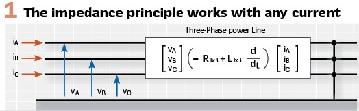
We must answer this question before addressing other issues. Consider a three-phase power line with a metallic fault of any type. Assume, as in Figure 1, that the source behind the relay injects an arbitrary current with a frequency spectrum around the nominal frequency. The term arbitrary means the currents can be small, heavily distorted, contain an ill-behaved negative-sequence component, have an unusual pattern given the fault type, and may have a noninductive character relative to the voltage at the source terminals. Does any of this matter for the distance protection principle? You can use an ohmmeter analogy when thinking about the apparent impedance measurement. An ohmmeter may inject current of any shape into the resistor under test, and yet the voltage impressed across the resistor allows measuring the resistance.
At relatively low frequencies, a three-phase power line behaves like a resistive-inductive (R-L) circuit. For a metallic fault, the phase voltages at the line terminal are linear combinations of phase currents and phase current derivatives. At the power frequency, the voltage phasors are products of current phasors and line impedances (a 3×3 impedance matrix determined by the zero-sequence and positive-sequence line impedances).
For simplicity, we can state that the voltage at the terminals of a faulted line is the product of the impedance between the terminal and the fault and the current at the line terminal
(V = ZAPP · I in frequency domain and v = R · i + L · di/dt in time domain). Moreover, and central to our discussion, the voltage-current relationship at the line terminal is independent from the level, shape, or symmetry of the currents.
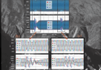
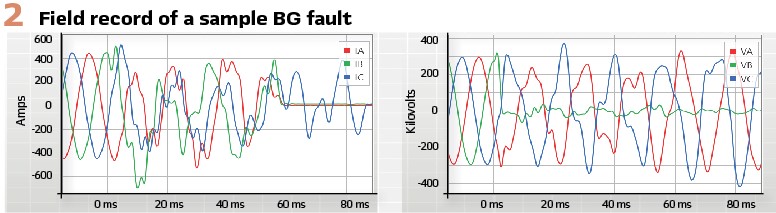
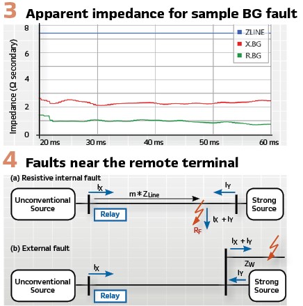
An unconventional source may supply an unusual current pattern with atypical unbalance between the phases and significant off-nominal frequency components, yet the voltages at the line terminals reveal the apparent line impedance (ZAPP = V/I) just like the voltage in an ohmmeter reveals the resistance under test (R=v/i). Figure 2 illustrates this key observation by plotting relay currents and voltages for a B-phase-to-ground (BG) fault on a transmission line where the system behind the relay is a wind farm. As expected, the currents are heavily distorted and do not show the pattern that is typical for a BG fault. Also as expected, the faulted phase voltage (VB) is very small. All relay input signals are heavily distorted; however, the apparent impedance in Figure 3 is relatively constant, and it correctly reflects the distance to the fault.
Three key challenges for distance elements
Logically, the following question presents itself: if the apparent impedance principle holds, why do we see issues with the present distance elements? Following is a summary of the three key challenges for distance elements. Understanding these phenomena and taking their conceptual models to their logical extremes will allow us to simplify and solve the problem.
Low inertia and variable source impedance challenge memory polarization: Today, relay manufacturers commonly use memory polarization in mho distance elements. Its primary purpose is to make the element reliably directional with a secondary benefit of improving dependability (coverage) for resistive faults through the effect of characteristic expansion.
Memory polarization works only when the source phase angle before the fault correctly approximates the angle during the fault – an assumption that requires high inertia in the system. An unconventional source has an exceptionally low inertia (wind-powered induction generators) or no mechanical inertia at all (inverter-based sources). During faults, the source voltage phase angle may change considerably with respect to the pre-fault angle. Also, an inverter-based source may incorrectly measure the system frequency during fault conditions. If so, the source may supply voltages and currents at a frequency that is unintentionally different from the system frequency. Additionally, the unconventional source impedance is not necessarily constant and inductive. This influences how the mho characteristic expands.
As a result of the source’s low inertia and atypical impedance, the mho expansion due to memory polarization can take an undesired form. Incorrect memory polarization is a serious issue and may result in a loss of security (reverse faults appear forward) or a loss of dependability (forward faults appear reverse).
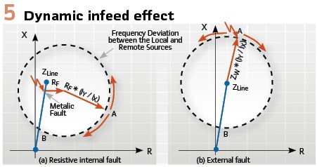
Low inertia makes the infeed effect dynamic: The low inertia of an unconventional source brings a new and important dimension to the classical infeed and outfeed effects and dramatically magnifies the associated challenges for distance protection. Consider faults located close to the remote terminal of the protected line, as in Figure 4.
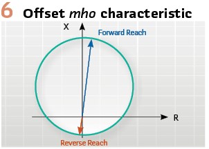
An underreaching distance zone must restrain for these faults, and an overreaching distance zone must stay dependably asserted for these faults. If all generators in the vicinity of the fault have high inertia, the ratio of the remote and local currents has a fixed phase angle, and the apparent impedance error yields an underreaching or overreaching effect depending on the relative phase angle between the local and remote currents (Figure 5). In systems with high inertia, the apparent impedance is stationary and located at the point marked A in Figure 5.
If the source behind the distance relay has an exceptionally low inertia and the forward fault is not cleared quickly, the remote and local fault currents may start rotating against each other. This in turn makes the apparent impedance follow the circular-shaped trajectory in Figure5, jeopardizing both security (Z1 overreaches) and dependability (Z2 underreaches or deasserts before timing out).
It is also important to realize that if the local source is unconventional and therefore weak, the ratio of the remote and local currents may be much greater than 1. As a result, the circle that represents the rotating movement of the apparent impedance in Figure 5 has a large radius, further exacerbating the problem.
Note, however, that the dynamic overreaching and underreaching effects take time to develop. To cause a severe overreach, the apparent impedance must move from Point A in Figure 5 at the beginning of the fault, to Point B later during the fault.
The higher the frequency difference (the lower the inertia), the faster the impedance movement, and the sooner the overreach or underreach occurs.
Negative-sequence current does not encode fault direction and type: The negative-sequence current at the terminals of a synchronous generator follows the negative-sequence voltage that the system imposes during faults. A synchronous generator can be represented by a fixed negative-sequence impedance, and therefore the negative-sequence current angle relative to other signals encodes fault direction and type.
Presently, unconventional sources do not supply a negative-sequence current that follows the negative-sequence voltage. The negative-sequence current may be small and variable, and its angle may change relatively quickly with respect to the positive-sequence voltage, and by extension, with respect to the negative-sequence voltage (directional elements) and the zero-sequence current (faulted-loop selection). In recent years, we have seen research papers on new ways of controlling inverter-based sources to improve protection operation, as well as attempts at standardizing the negative-sequence response of the source. These are positive developments, but they inadvertently add uncertainty to the issue of fault response.
A typical distance element may use the negative-sequence current for directional supervision and faulted-loop selection and – in the case of a quadrilateral characteristic – to polarize its reactance comparator. As a result of the ill-behaved negative-sequence fault current in applications near unconventional sources, distance protection elements may lose security, dependability, or both.
Worst-case assumptions instead of exact knowledge of source fault response

Unconventional sources not only respond differently to faults than synchronous generators, but that response is not universal. It depends on the source type and design and the grid codes that the source was configured to follow. Unless and until the unconventional source characteristics converge naturally or become universally standardized, a sound approach to protective relaying near unconventional sources is to not attempt to discover and use characteristics of the unconventional sources but to devise protection principles that are as independent from the source characteristics as possible. Not counting on any specific fault response but working with worst-case assumptions makes the task of devising new distance elements possible and practical. Specifically, our design adheres to the following worst-case assumptions:
- The use of memory polarization and negative-sequence current in distance element logic should be avoided in applications near unconventional sources
- Mho expansion in applications near unconventional sources does not bring the expected benefits, even when the unconventional source perfectly follows the system frequency. Making memory polarization work under frequency excursions does not solve the problem of variable source impedance
- If a low-inertia source behind the relay cannot maintain frequency during faults (maintain tight synchronism), then 1) the underreaching distance elements can be enabled only for a brief time – if enabled permanently, they may overreach for out-of-zone slowly cleared faults and 2) the overreaching time-delayed distance elements can face dependability issues unless their operating characteristics are shaped to accommodate dynamic infeed and outfeed effects
One may argue that the above assumptions are too pessimistic. For example, during single-phase faults, a low-inertia source is less likely to experience large frequency excursions; or when the relay polarizing memory voltage decays quickly, the frequency excursion problem is not that detrimental; or when the fault resistance is small, the dynamic infeed effect is less detrimental to Z1 security; or if the source’s phase-locked loop is designed well, it is less likely to exhibit large frequency errors. All of this is true, but to use these observations, one would have to quantify them, resort to modeling, and have detailed knowledge of the sources. Not having to quantify the degree of the problem but working from the worst-case assumptions enables us to move forward and devise a solution that works independently of the source fault response.
It is worth comparing our approach with an even more simplified protection idea of using inverse-time undervoltage schemes, especially for backup protection. While it is true that inverse time undervoltage protection has merit, its underlying foundation of not using the current signal at all is going too far. The current signal can be used in distance elements even when driven by unconventional sources, and using it helps to detect faults better than using the voltage signal alone.
The following paragraphs summarize the key elements of our solution.
Offset replaces polarization in mho distance elements
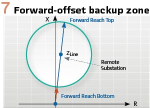
A simple way to avoid issues with memory or cross-phase polarization is to apply an operating characteristic that is offset in the reverse direction (Figure 6). The offset characteristic’s forward reach is set according to the application (Z1, Z2, remote backup), and its reverse reach is set to ensure dependable operation for close-in forward faults. Of course, the offset impedance element is nondirectional and will operate for any fault that falls inside the characteristic, both forward and reverse. To make the element directional, we will need to supervise it with a proper directional element. This, however, is nothing new; all quadrilateral distance elements are designed this way. Moreover, some distance protection applications – primarily the step distance protection – do not have to be directional. By using offset, we do not patch the polarizing logic, but instead, we avoid directional polarization entirely. The resulting design not only works well with unconventional sources but is also simpler compared with the present mho elements.
Loop current replaces negative-sequence current for quadrilateral element polarization
Not being able to depend on negative-sequence current for polarizing adaptive reactance comparators in quadrilateral distance elements, we resort to using the loop current to polarize the phase elements and either the loop or zero-sequence current to polarize the ground elements. This simple approach may appear to hurt performance during resistive faults; however, this is not the case. The infeed and outfeed effects near unconventional sources are dynamic (Figure 5) and cannot be solved with adaptive polarization.
Undervoltage replaces current-based faulted-loop selection
Not being able to depend on negative-sequence current to identify the faulted loop(s), we use voltage signals instead. Unconventional sources are weak, and as a result, the faulted-loop voltage(s) decreases dramatically during fault conditions. Therefore, in applications near unconventional sources, a logic that is based on voltage sequence components or a plain undervoltage principle detects faulted phases correctly and dependably. Voltage-based faulted-loop selection is a tried-and-true solution, commonly used in the weak-infeed logic of POTT schemes. We borrow it and apply it directly to the distance elements.
Step distance zones do not have to be directional
Many line distance relays offer only directional distance zones, either forward or reverse. We apply step distance protection by attaching timers to those instantaneous directional zones, and by doing so, we obtain directional step distance zones. However, directional operation of step distance protection is not always required. It can even be detrimental when the memory polarizing signal expires while the scheme is timing out. The directional time-delayed distance element may, as a result, lose directionality during close-in metallic faults, such as when closing on safety grounds that were inadvertently left in place on an adjacent circuit connected to the local bus.
Step distance protection coordinates primarily through a time delay. While maintaining a desired forward and reverse reach is important for time coordination, step distance backup applications do not have to be directional. Tripping after 0.5 s is as acceptable for uncleared faults in the local substation as it is for faults in the remote substation. An offset characteristic (Figure6) provides dependable step distance protection and avoids the polarization challenges altogether.
Given the dynamic nature of the infeed and outfeed effects, it is beneficial to shape the step distance zones to allow room for the circular trajectory of the apparent impedance (Figure 5).
Figure 7 shows an example of a forward-offset mho characteristic well suited for providing step distance backup for the remote substation.
Zone 1 security
The dynamic infeed effect caused by low inertia and a fast angle slip between the system and the local unconventional source jeopardizes Z1 security far beyond the margin that a mho arc or a reactance tilt can provide. The dynamic infeed effect (Figure 5) can be understood as a fault that initiates a power swing right away, even before that fault is cleared. An attempt to enhance a traditional power-swing blocking logic to detect this phenomenon would face significant difficulties for several reasons. It is better to simply take advantage of the time lag between the fault inception and the swing onset (at least a few tens of milliseconds).

We can allow the Z1 distance element to operate in a short time window following assertion of the starting logic. Instead of detecting a power swing combined with the fault, we simply assume the worst-case scenario that such a swing may develop right away. We give Z1 a time window in which to operate if the fault is on the protected line, and we shut it down afterward to avoid security issues if the fault is external.
Directional supervision
Distance applications that require directionality include the directly tripping Z1 and the overreaching Z2 in a POTT scheme when no weak-infeed logic is used or when both line terminals connect weak and unconventional sources (expected scenario in future grids). The zero-sequence directional elements work well, owing to the zero-sequence current in the grounded windings of step-up transformers that connect unconventional sources to the system. These elements can be successfully used to supervise the nondirectional ground impedance elements. Of course, we can count on the zero-sequence directional elements only during ground faults.
The incremental-quantity directional elements work correctly near unconventional sources for both ground and phase faults. They reliably detect forward faults as long as the circuit behind the relay is inductive. When a machine source feeds the fault current, the circuit is undoubtedly inductive. When an inverter-based source feeds the fault current, the circuit is inductive for at least several milliseconds before the dc voltage responds to the fault condition and the control algorithms start modulating the source output. Therefore, the incremental-quantity directional elements can be trusted in the first few milliseconds of the fault. Their drawback is that their initial assertion must be extended by using a timer if they are used to supervise slow or time-delayed protection elements and logic.
We propose a new type of directional distance element that we label a “weak-infeed distance element”. The new logic draws inspiration from the weak-infeed pilot logic (Figure 8a). When the weak-infeed pilot logic receives a permissive signal, it becomes aware of a fault in front of the remote relay, it confirms the presence of the fault locally by looking at the undervoltage or voltage unbalance condition, and it operates if the fault is not a reverse fault. The key principle is to rely on the strong remote source to excite the relay at the weak terminal during reverse faults.
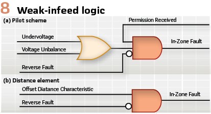
We borrow this tried-and-true solution to directionalize distance elements at weak terminals (Figure 8b). The nondirectional distance element detects a fault. If the fault is not in the reverse direction, then the fault must be forward, and the element can trip. The logic counts on the strong remote source for detecting reverse faults instead of counting on the weak local source to detect forward faults. The logic is simple and works reliably. It requires, however, an overcurrent supervision for the reverse-looking directional element to be set below the reverse fault current and above the forward fault current. With a proper overcurrent threshold, we can apply a distance or negative-sequence directional element as the reverse-looking element in the blocking logic in Figure 8b. The combination of the zero-sequence, incremental-quantity, and weak-infeed directional elements allows us to directionalize the offset impedance characteristics and achieve dependable directional distance protection.
Biography:

Bogdan Kasztenny specializes in power system protection and control. In his decade-long academic career, Dr. Kasztenny taught power system and signal processing courses at several universities and conducted applied research for several relay manufacturers. Since joining the industry in 1999, Bogdan has designed, applied, and supported protection, control, and fault-locating products with their global installed base counted in thousands of installations. Bogdan is an IEEE Fellow, a Senior Fulbright Fellow, a Distinguished Member of CIGRE, and a registered professional engineer in the province of Ontario. Bogdan has authored over 220 technical papers and holds over 55 patents.