by Mital Kanabar, GE, Canada, Nathan Dunn, GE, USA and Camilo Dearriba, GE, Spain
WIDE Area Protection, Automation and Control (WAPAC) are deployed to protect the integrity of grid by maintaining grid reliability and resilience. WAPAC are also referenced and installed as System Integrity Protection Schemes (SIPS), special protection schemes (SPS), Remedial Action Schemes (RAS). WAPAC can be implemented among substations (distributed) or between substations and control center (centralized).
The major communication infrastructure considerations for WAPAC system are:
1) High-speed performance delivery (short delays over WAN)
2) Network bandwidth requirement (i.e., optimum information/dataset and data rate)
3) Cyber security considerations
4) Availability/Redundancy
Four WAPAC case-studies are highlighted in this article which has opened a large field of R&D to provide the system level solution to integrate more renewable resources for accelerating the energy transition. Conventional system evolved from a network based on conventional generation with large-inertia synchronous machines, to a network based on distributed & lower-inertia renewable generation dominated by power electronics.
The first case-study implement centralized RAS with 50ms performance requirements used Routable-GOOSE with cyber security mechanism.
The second case-study on automated stabilizing system for an island with HVDC link delivers performance within 70 ms.
The third case-study of delivers safety and enhanced resilience over distribution network by detecting high-speed falling conductor protection performed before the conductor fall to the ground, in less than 200 ms. Finally, the fourth case-study on multi-area regional power balancing generator governor controls in few seconds to deliver resilience in cases of storm and other extreme weather conditions.
CASE STUDY-1 on Secured R-GOOSE based R-Remedial Action Scheme
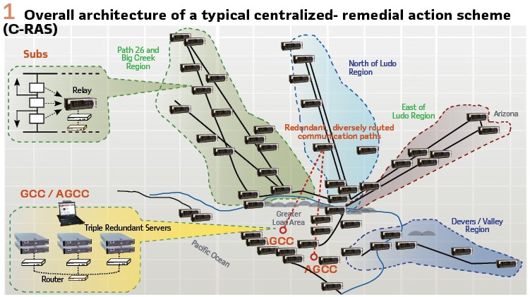
GOOSE is an industry recognized mechanism for time-critical peer-to-peer communication among Intelligent Electronic Devices (IEDs). For wide area network, Routable-GOOSE is used for Centralized Remedial Action Scheme (CRAS) project which replaces existing individual RASs, as shown in Figure 1. CRAS implements special protection schemes that enable an automatic protection system to maintain system reliability by detecting abnormal or predetermined system conditions and taking corrective actions other than (or in addition to) the isolation of faulted components.
The main functional components of CRAS include:
1) Field devices (monitoring and mitigation devices)
2) Communications networks (IGMPv3 enabled Gigabit Ethernet/IP links)
3) Central Controller Systems (CCS)
IEC 61850 extends the application of GOOSE from LAN to WAN, either using tunneling or allowing GOOSE to multicast over IP networks using IGMPv3 protocol. These R-GOOSE messages are routed over layer-3 routers with UDP/IP headers. Security mechanisms for R-GOOSE are also available in IEC 62351-9 and enable several applications of high-speed and secured R-GOOSE for WAPAC.
The system is fully redundant with duplicated A and B subsystems operating in parallel. Each A or B subsystem will have its own CCS, monitoring relays, mitigation relays, and communication network infrastructure (complete independent system). The central controller for each A or B subsystem is designed with triple redundancy (2-out-of-3 voting) and installed in secure and geographically separated locations: Grid Control Center (GCC) and Alternate Grid Control Center (AGCC).
Each substation will have two sets of relays, one for C-RAS A, and the other for C-RAS B. Between GCC and AGCC, there will be two redundant and diversely routed Gigabit Ethernet links to exchange System A and System B information coming from the substations.
Relays at the substations are either monitoring or mitigating relays. Monitoring relays report loading of critical lines to the central controllers every few seconds. They also report trips of these lines – normally due to relay action – within milliseconds so that the controller can implement a strategy to mitigate the resulting overload on the remaining lines and preserve system stability. Mitigating relays at substations or generating locations receive control commands from the central controllers to shed load or generation.
The relays in a substation have their communications isolated to either System A and System B. A particular substation may have both monitoring and mitigating relays.
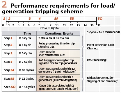
Performance Requirements: Of the entire system performance of 16 cycles for C-RAS, three cycles (e.g. approximately 50 ms) are allocated to communication and controller/logic latency. Of the 50 ms, 38 ms are designated for communication latency and 4 ms for controller reaction time, shown in Figure 2. The 50 ms allows for an operational variance of 8 ms.
IEC TR 61850-90-5 security mechanism for R-GOOSE has the following options:
1) None
2) Signature (i.e. Authentication)
3) Signature and Encryption. Application message has a session layer, which provides security and management via Group Domain of Interpretation (GDOI) protocol described in IEC 62351-9.
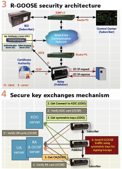
The key exchanges uses GDOI provides the capability of a Key Distribution Centre (KDC) to provide symmetric keys securely via either clients requesting the keys or the KDC pushing keys to the appropriate subscribers. (Figure 3).
Figure 4 illustrates the simplified sequence of events to establish secured communication among R-GOOSE publisher and subscribers. There are two major exchanges involved:
1) Certification which is used to authenticate all devices exchanging keys
2) Security Association (SA), followed by the distribution of symmetric keys used by the publisher/subscriber for signature and encryption
CASE STUDY-2 on Automated Stability Connecting Islands with HVDC Links
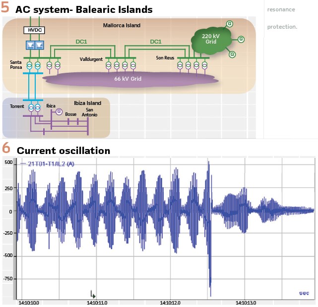
The Spanish transmission power system owned by Red Eléctrica de España (REE) includes a submarine high voltage direct current (HVDC) link laid in the Mediterranean Sea that connects the Mallorca Island with the Spanish mainland. A 244-kilometer-long mass impregnated submarine DC cable connects both converters, one in the Santa Ponsa 220 kV substation, near the island’s capital city Palma de Mallorca, and the other located in the Morvedre 400 kV substation, near Valencia. (Figure 5).
Because of the HVDC technology used, which is Line Commutated Converter (LCC), the operation of the link requires a minimum short circuit power of 500 MVA in the connection points with the AC network. The amount of power that manages the HVDC system in relation with the total demand in the Balearic system, which is approximately 1000 MW, requires an ultrafast switching of the operation mode in the HVDC link when operates near to it short circuit limits.
WAPAC with Automated Stability Phasor-based Algorithm System (ASPAS) allows to optimize the operation with the consequent economic benefits. To accomplish the goals, it is critical to have an accurate on-line estimation of the short circuit power in Santa Ponsa substation. After analyzing different alternatives to estimate the short circuit power, a novel process was decided based on the topology of the nearby network, the measurements of electrical magnitudes in some selected substations, and an algorithm running calculations based on a previous “off-line” big data and statistics methodology analysis.
The short circuit power estimation result from the process determines if a change in the operation mode of the HVDC is needed. We need to remark that for all this process to be effective, it must be done very fast; in less than 70 ms.
In Figure 6, is observed a current oscillation due to a trip on Santa Ponsa – Valldurgent circuit (DC1 on Figure 1), due to this trip the HVDC link is working only with 220/66kV transformers in Santa Ponsa, the ones in service condition after trip, this grid situation produces a current oscillation (power) unacceptable for a safe grid operation.
Figure 6 shows the oscillation from one phase of one HVDC pole event that provokes the trip of the link by subsynchronous resonance protection. This oscillation is harmful for electrical system, not only for the affection to generation and loads on island due to grid voltages oscillation, but also for overvoltage produced in close trip instants of HVDC link due to filters operation to low short circuit power currently in grid.
The technical solution developed measures voltages and currents in different points of the network and calculating the active power through some lines locally using Phasor Measuring Units (PMUs). The Active Power values are transmitted to a Phasor Data Concentrator (PDC) located in Santa Ponsa Conversora 220 Kv substation, where the information is processed, the calculation is run, and finally a decision is made. The solution implemented is based on synchrophasor technology, IEC 61850 communications for commands, Phasor Data Concentrator (PDC) using Power software Package which has embedded the protocols IEC 61850 Edition 2 Client/Server and IEEE C37.118 collecting raw data from the IEDs, a powerful Soft PLC processing the data and calculating the remedial actions sending the results in fast GOOSE messages to IEDs, and an operator HMI to visualize system condition and change the threshold levels without system disruption.
The system architecture implemented is as seen in Figure 7.
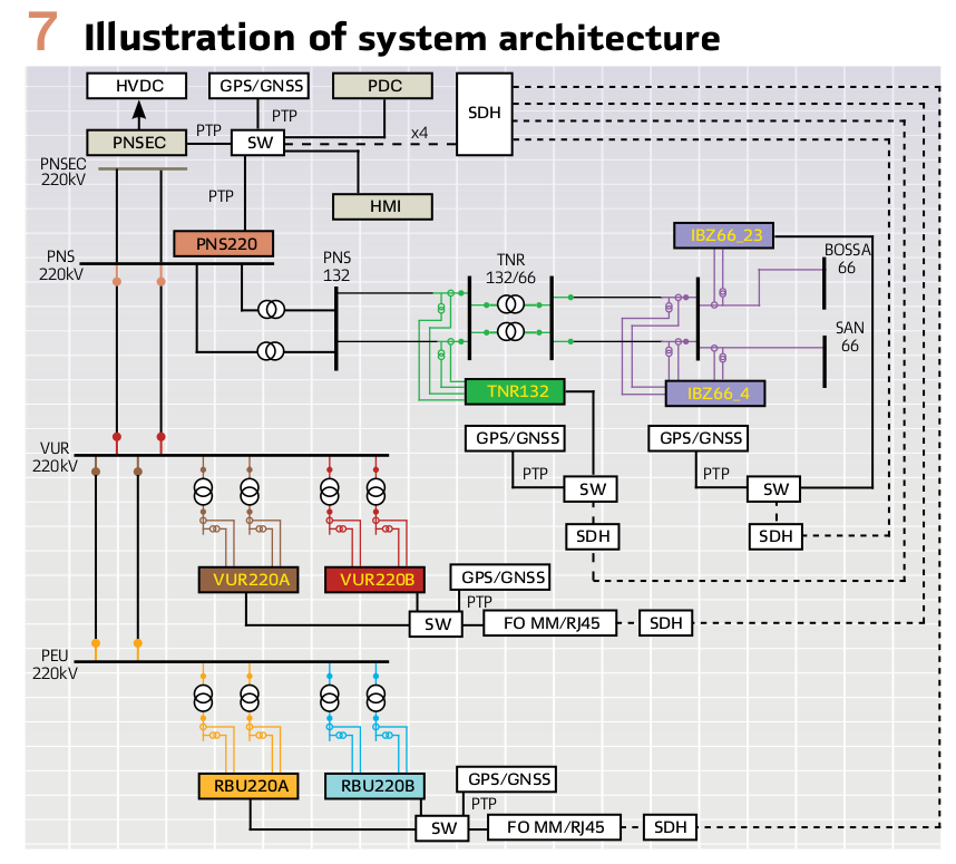
In the HVDC substation a PDC is installed where the information is processed, the calculation run, and finally a decision is taken and transmitted through IEC 61850 GOOSE message to a N60 network relays placed in this substation (PNSEC), which actuates to HVDC control system. Also, this PDC repacks all synchrophasor information, changing its sample rate and sending it to phasor control center in Madrid (Spain) in different synchrophasor frames. All the operation data, system status, alarms, events and trends can be seen in HMI placed in same substation. All the communication is in a dedicated LAN on each substation and interconnected to others with a dedicated SDH network with a maximum bandwidth of 10Mbps creating a dedicated and redundant ASPAS grid for each manufacturer.
For better maintenance purposes, and as a GOOSE communication is populated over the ASPAS grid. Several tests have been carried out to simulate every event and every power level affecting the HVDC stability, checking at the same time that the response time of the complete system is below the specified operation time. Time obtained was in the range of 30 to 40 ms. Site tests were carried out by synchronizing secondary injection sets in 4 substations by means of using IEEE 1588 PTP synchronization protocol available in one ASPAS network.
Overall WAPAC system in ASPAC project benefits are as follows:
- Economic: It is not needed to increase the generation in the Balearic system (greater cost than the peninsular one) due to the limitation of the HVDC link
- Environmental: Prevents conventional generation in Balearic system to cover the limitations imposed by the HVDC, which contributes to a more sustainable Balearic energy mix
- Technical: After contingencies, prevents the HVDC link can be kept operating with low short-circuit power, which can cause damage to the converter station and the transmission network close to it
CASE STUDY-3 on Falling Conductor Protection for Distribution Systems
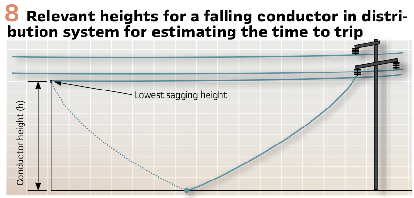
An energized overhead power line may break and fall to the ground or other surrounding objects due to reasons such as severe weather conditions, conductor aging, natural disasters, hardware failures, and/or pole knock-over. When the falling conductor touches the earth or other grounded objects, it may cause a high-impedance (Hi-Z) fault which cannot be detected reliably by conventional overcurrent protection schemes. While current-based algorithms using negative-sequence components (e.g., the ratio of) can detect most broken conductor faults in transmission systems, their efficiency is compromised in distribution systems. The performance of Falling Conductor Protection schemes in distribution systems depends on several factors such as feeder topology, penetration level of Distributed Energy Resources (DERs), broken phase location, single-phase switching, and/or protection philosophy (e.g., type of protective devices).
This case study proposes a synchrophasor-based algorithm to reliably detect and de-energize broken overhead lines in distribution systems using PMU data inside the substation and along the feeders. The effectiveness of the proposed algorithm has been validated with Hardware-in-the-Loop (HIL) testing of realistic distribution feeders using a Real-Time Digital Simulator (RTDS). A comprehensive set of cases were tested including internal/external broken conductors, internal/external faults, various DER penetration, different load levels, and transient/switching incidents. The test results show that the proposed algorithm can detect and trip broken conductors reliably. Therefore, the proposed High-Speed Falling Conductor Protection (HFCP) scheme will be able to de-energize the affected circuit prior to the conductor hitting the ground, eliminating the risk of an arcing ground fault or energized circuits on the ground. For this specific system, falling conductor time was calculated around 1.06 seconds, and the system can detect within 200ms, which allows time to take other actions, such as blocking auto-reclosing and enhance safety of the overall distribution system. (Figure 8).
As shown in Figure 9, the modeled distribution feeder has three PMU devices on its branches (PMU1, PMU2, and PMU3) and one PMU device at the substation (PMU0). The PMU devices on feeder branches communicate measured currents and voltages to the real-time logic engine through a radio channel.
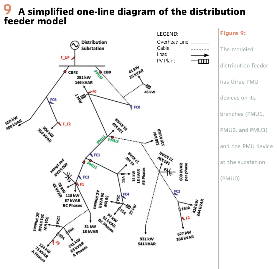
The PMU device at the substation communicates its measured values with the real-time logic engine using Ethernet cable or fiber optic (all in IEEE C37.118 protocol). Fault locations F0 to F3 are located on the feeder of interest, while faults F2 and F3 would cause a fuse-blown condition because these faults are situated downstream of fuses.
Moreover, the model of the system embeds five broken conductor locations on the feeder of interest which are identified as FC0 to FC4, while there is also a falling-conductor location on the neighboring feeder (FC6). FC6 is simulated to evaluate the impact of an out-of-zone falling conductor on the performance of the HFCP algorithm.
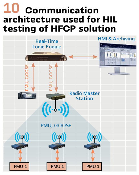
The communication architecture for the HFCP solution is shown in Figure 10. The PMU devices located downstream of the substation send associated measurements to the radio master station using a wireless channel. These data are then sent to the RTC to be used by the HFCP algorithm. The internal variables of the HFCP algorithm including the impedances measured at the location of each PMU device is also sent to the workstation for monitoring and archiving. The solution can be accompanied by an HMI, which allows the user to interact with the HFCP system and monitor the status of the system.
To evaluate the performance of the HFCP solution, 188 broken conductor cases, 32 control cases, and 168 fault cases were tested. Seven possible fault types (AG, BG, CG, ABG, BCG, ACG, and ABC) at different loading levels with and without the utility-scale DER are included in the 168 fault scenarios. Single-phase falling conductor at different loading levels and different phases with and without the presence of the DER form the 188 broken conductor test cases. For control scenarios, 32 switching operations at all the breakers shown in Figure 9 at different loading conditions and with and without the DER are conducted.
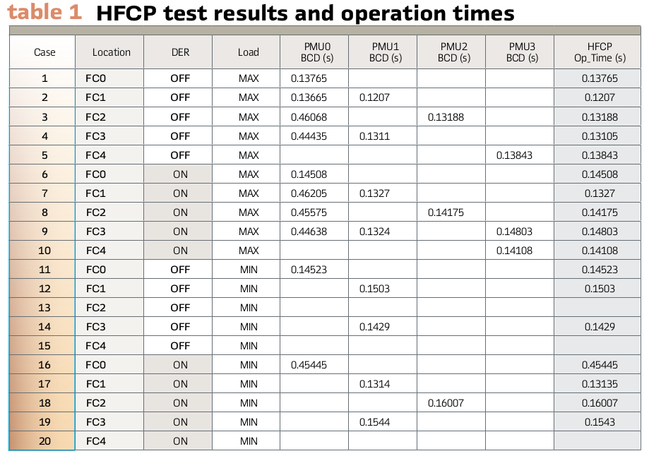
Table 1 shows a selection of test results for HFCP HIL testing. The test results cover broken-conductor events at minimum and maximum loading of the feeder, which correspond to 20% and 100% feeder loading, respectively
Summary
Grid reliability and resilience are not only important from regulations perspective, but also support one of the key aspects of Energy Trilemma, i.e., Energy security. With integration of more renewable energy resources are lower inertia distributed across wider regions across the grid. Overall system inertia is decreasing, which will reduce the system control reaction time. There will be need for a middle layer Automation & control between centralized control center layer and substation protection layer to take control across the regional level. This middle layer can be achieved using Wide-area protection, automation, and control (WAPAC) system which may use peer-to-peer R-GOOSE or client/server PMU/PDC architectures.
WAPAC can be customized to solve the targeted regional grid issues within the given performance constraint using R-GOOSE and/or PMUs over secured communication network. WAPAC delivering grid reliability and resilience may require performing system studies to identify the performance requirements & local regulations.
Biographies:

Mital Kanabar is Chief Applications Architect & Office of Innovations Leader at Grid Automation, Grid IQ Center, in Markham, ON, Canada. Mital has 15+ years industrial R&D experience and received his Ph.D. from University of Western Ontario, Canada. Mital holds 14+ international patent applications, contributed to 50+ journal/conference papers, 5 industrial magazine articles. He is also serving as a Chair of IEEE PSRC WG H47 (Digital substation); vice-chair of WG C40 (PDC standard); and Secretary of WG H45 (Centralized P&C); and participate at various technical working groups at IEC/CIGRE/NERC, Linux Foundation Energy (LFE), and other industrial technical community groups.

Nathan Dunn is the Global Grid Modernization Services Product Manager for GE’s Grid Automation business. He is responsible for leading the Product Line for Distribution and Microgrid Solutions as well as leading the Grid Modernization Center of Excellence team. This involves for working across GE teams to develop, execute, and lead Grid Automation’s strategy for products, solutions, and services. Nathan started his career at GE as a Field Engineer and held positions inside Operations and Services Management prior to joining SEL as a Key Account Manager and Regional Sales Manager. Nathan joined back GE in 2019 as the Global Business Development Services Leader for Grid Automation. Nathan earned a B.S. in Electrical Engineering Technology from University of Pittsburgh and an MBA from the University of Maryland.

Camilo De Arriba received the bachelor Electrical Engineering degree from the UPV in Bilbao in 1994 and joined GE in 1996. He worked in different areas. Now he is R&D Manager for Advanced Automation Applications in GE Grid Solutions. He has large experience as Project and Technical Manager leading the execution of many challenging Projects worldwide. He is PMP certified and has an MBA master’s degree. He was one of the Authors of the paper generated by the CIGRE WG B5.42.