by Robbert Koenderman, Qirion B.V., The Netherlands, and Christian Brauner, OMICRON electronics GmbH, Austria
In recent years the need for energy has been extremely increased, setting the network companies for a great task. Expanding the power grid by building new substations and more cables in the ground is time consuming, and the energy transition is going faster. Therefor Alliander is looking for other options to upgrade the power grid and make better use of the different components. To do so, one thing is becoming more important and that is data. Useful data that can be transformed into useful information. To collect more data from the power grid the substations will be more like digital substations.
Changing the sub stations into digital substations not only changes engineering of the substations but also commissioning the substations. Besides changing the way of testing we also need to test faster, efficient and smarter.
To achieve this, we are using the substation automation testing tool (SATT) for testing digital substation automation systems (DSAS). The SATT is the tool that can help you test in Green- Brownfield projects as in conducting research during failure in a substation automation system.
For several years Qirion has been using SATT as a tool to test faster, smarter and more efficiently. SATT can be used in Green- Brownfield project as in conducting the research during failure in an automation system. The first part of this article will describe the way Qirion uses the SATT during Greenfield projects.
Commissioning a substation automation system strongly depends on the way the system is constructed. Therefore the whole engineering of a substations is changed. By applying modular construction, configuration typicals for automation systems and pre-established test plans. We were able to commission a substation more efficient, faster and smarter.
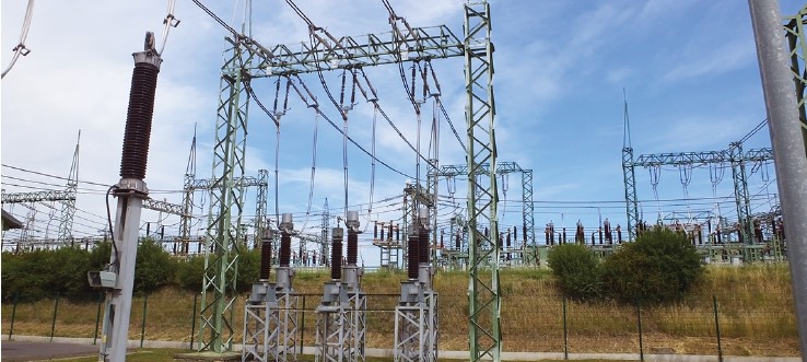
Qirion which is the substitute within the Alliander organization is responsible for engineering, building, commissioning and maintaining of the high and medium voltage substations in the working area of Alliander. In order to cope with the large work requirement of building substations, Qirion has developed a standard for the fast and efficient construction of substations. This consists of standard medium volt installations, transformers design, and building design. This is set up according to the modular building principle. (Figure 1).
For the substation automation systems, we have developed a standard Input-Output list, standardized hardware connections and standard pre-tested configuration typicals for the automation system. During the engineering, building and commissioning phases there are different moments of testing. Within Qirion the department Operational Technology is responsible for engineering the automation system and test the configuration. There are three moments of testing throughout the process.
First, we have the typical testing, this testing is done after the typicals are made or changed. During this test the hardware components (IED’s) are fully tested on all the functionality that has been configured. To simulate the primary installation, we use a test RTU which can energize the input and measure the outputs. The test device is then used to test the current and voltage. When the typicals are tested and approved they can be used in the projects for engineering the system.
Second, after the automation system is fully configured the PAT (Production Acceptance Test) is performed. This PAT is done in a test lab. This is a controlled, safe environment for complete testing. Because the typicals used in the configuration are completely tested the hardware IED’s are not needed for testing. In this test all the information from the IED’s to the gateway, according to IEC61850, is tested. Also, the information to and from the gateway to the HMI (human machine interface) and SCADA (central control room) is fully tested.
The last test is the SAT (site acceptance test), this is done on site with the actual primary installation. Here all the hardware connections from the medium or high voltage installation is tested for the right connection and functionality working. Because the automation system is already tested, any issues found during this test can only be caused by hardware wiring and faulty primary equipment.
In this article the PAT (production acceptance test) will be described. The way the configurations are tested has evolved during time because of the large amount of systems that must be tested. And the availability of new test equipment.
Commissioning a PAC system during the production phase.
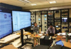
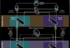
Every configurated automation system must be tested before it is implemented in the substation. Within Qirion we call this the Production Acceptance Test (PAT). One of the important reasons of implementing this test is that testing the configuration in a secure and safe environment reduces time and increases the efficiency. The configuration typicals for the IED’s are tested with a test RTU. This RTU enables us to simulate a primary installation and give us the opportunity to test the hardware IED and configuration completely. The typical can then be used by the engineers to configure the complete system. See Figure 2 for the set-up of the test system for testing the IED typicals.
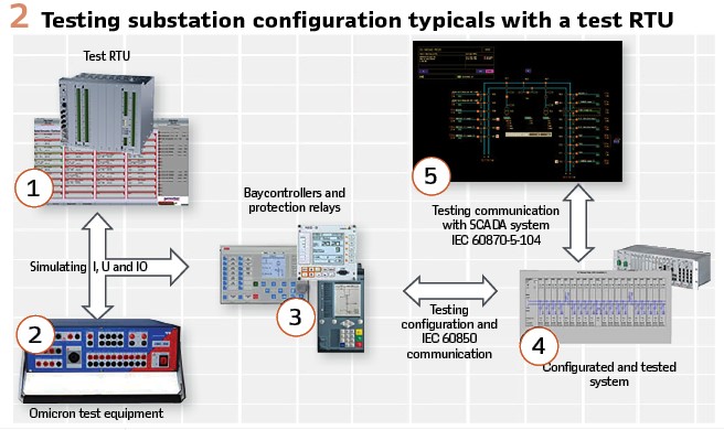
1. The test RTU we used to simulate the primary installation. So, it is possible to give commands locally trough the HMI and via the central control room. This is then exactly according to the used protocols (IEC6870-5-104 and IEC61850, using SELECT BEFORE OPERATE). With a touch screen it is possible to energize the input of the IED’s and measure the outputs
2. Using a protection test device we can inject the currents and apply voltage to the bay controller. The calculated power (P and Q) are then send to the gateway. We also test the protection functions within the relay
3. Our test system uses standard connection, so every IED, supplier independent, can be tested with this test system
4. All the information from the IEDs is sent to the gateway and or RTU which allows us to test the complete configuration, this includes the HMI testing
5. Because there is a secure connection between the test lab and the network control center, we can easily test the complete communication and data between the gateway and control room
Testing configurations in this way has some advantages but also disadvantages.
The advantages are:
- Testing with the actual hardware IED enables you to completely test the IED configuration
- End-to-end test from IED to SCADA is possible
- The ability to test the logic schemes configured in the IED’s
- Pretesting of the configuration in a safe and secure environment
- This way of testing is preferred for typical testing
The disadvantages are:
- Test RTU is limited to test only 5 IED’s at the time. After finishing the IED’s must be loaded for other bays. This cost a lot of time
- Goose configuration used for interlocking cannot be tested completely, because not all the bays are present
- Goose configuration used in installed base cannot be tested if the hardware that is operational is not present for testing
- Takes time to build the test system and faults can arise in hardware connections
For testing the complete configuration of a substation automation system, it’s not always necessary to have all the hardware IED present. The hardware IED used in the substation automation system are pre-mounted by a third party. Testing a configuration with all the necessary hardware components is a time-consuming and cost-increasing activity. And that’s just not what we want.
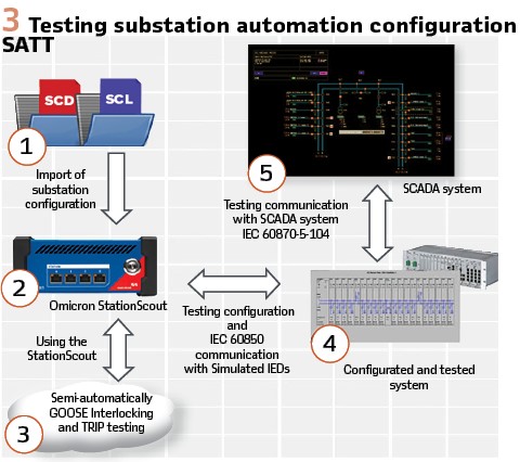
Because the automation systems are configured to communicate with the use of the IEC61850 protocol, and the fact that the automation systems became more and more data driven, a new way of testing the configuration for new and installed base automation systems was needed. With SATT it is possible to simulate the whole substation automation configuration. By simulating the IED’s its quite simple to simulate the information from the IED’s to the gateway and therefore also to the SCADA system. When configurating a substation automation system, a SCD-file (substation configuration description) is generated. In this file all the information about the IEDs, network configuration etc. is stored. Such a file based on the IEC61850 standard can be imported into the SATT and can then be simulated. The only hardware component that we use is the gateway. And that is just the only system we test during the PAT test. See Figure 3 for the overview when testing with the SATT.
The simplest way to test a substation configuration system is to create an event/alarm or measurement in the IED. And see the reaction of the rest of the systems. Like the HMI or the SCADA system.
1. The SCD file is imported in the SATT where it is possible to select which bays you want to test, and which components to simulate
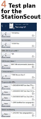
2. In the SATT it is easy to generate a test plan that lists what you want to test. (See Figure 4)
3. Because all the IED’s are present the GOOSE communication is working as configured. Interlocking can easily be tested almost automatically
4. With all the MMS traffic present, all the events, alarms, measurements, commands and switching commands can be tested with the gateway/RTU.
5. Also, all the information for the SCADA is tested
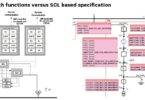
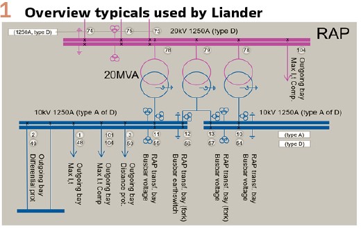
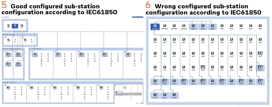
When testing using the SATT it’s very important to create a SCD file according to IEC 61850. This sounds logical but this also means naming the IEDs right and dividing them on different installations and voltage levels. Otherwise, the single-line diagram won’t be drawn the right way. At this moment we create our SCD files with the station configurator from Siemens or the PCM600 software tool from ABB. See Figure 5 and 6 for the difference in stations layout. While Figure 5 display a correct SCD file layout. Figure 6 display a layout with a bit chaotic layout.
As described in the first part the article, utilities today are faced with heavy workload due to the increasing number of substations needed for the ongoing transition to an electricity supply based on renewable power sources.
Efficient roll out of DSAS in multiple substations by standardization
A common solution for larger utilities is the implementation of digital substation automation systems (DSAS) based on standardized building blocks such as typical bay configurations and to implement long time frame contracts with product vendors and system integrators for deliveries and services. Such frame agreements are often tendered once in a period of 3-8 years and shall standardize the system configuration as much as possible during the frame period.
These frame contracts normally start with an implementation phase where the typical bays are specified (e.g. the process signals, LCD screens, interlocking logics to be implemented, etc) by the owner and the IEDs will be configured by the vendors accordingly.
The result is a set of files and documents per typical bay such as the signal list, the IED’s configuration parameters (including hardware configuration, installed firmware version but also the Engineering tool versions) and the corresponding drawings and other documentation.
The bay typicals are thoroughly tested in the factory, finally approved by the employer and often fixed for entire frame period. For any DSAS project in a particular substation, those files are then deployed by “copy& paste” from the bay typical template to the real feeder installation with only a few modifications. As long as the bay typicals are already fully tested, the testing efforts of the SAS can be reduced, e.g. by testing just sample signals or controls and not the entire signal range.
Regular Patches and Firmware Updates Caused by Security Issues
Today, new security regulations conflict with the concept of fixing the firmware version of IEDs and other components of the DSAS for the entire lifetime of the system but as soon as security vulnerabilities are reported in the installed IED version, patching or updating IED’s firmware may be required in the energized substations.
To minimize the risk of malfunctions and interruptions at the live substations, full or at least partly retesting of the bay typicals before deployment to the energized substation is a proven solution. With the retested bay typicals, the onsite tests after the patch procedure can be a reduced to sample test of some signals and control commands.
At large utilities, a significant number of bay typicals are in use and as new firmware releases of IEDs are often published several times per year, the testing efforts become tremendous as long as retesting is performed in the traditional manual way.
Therefore, network companies require tools which support partly or fully automated testing of the DSAS after firmware patch. Such automated tests can be very useful not just for testing the regular firmware patches and updates but also for the initial system tests in the workshop or during commissioning of the DSAS.
Basic principle of the traditional End-to-End test
For testing the DSAS, the “end-to-end” test is the testing procedure, which is preferred by many utilities.
The aim is to test the functionality of the DSAS using physical components such as the IEDs, the substation network, local HMI and SCADA gateway built up in a testing workshop. As the primary system is normally not available during the tests, it is substituted by a PLC-based process simulator. In most cases today, the process simulator is manually controlled by the tester with the result of long testing time and sometimes even several testing engineers needed at the same time to perform the required tests.
Automation of the End-to-End tests
When the process simulator is equipped with an IEC 61850 server function, it can be controlled by the test tool and consequently the testing procedure can be partly or fully automated. (Figure 7).
The test tool can now trigger any alarms or set any switch positions at the process simulator and accordingly verify the correct processing of the signals within the IED as well on the station network. If the process simulator also includes logics for simulation of breakers and disconnectors, control commands can be initiated to the IEDs by the test tool and the responding change of switch positions can be verified automatically. (Figure 10).
Automated signal and logics tests
Automated test with real IEDs and process simulator: With the availability of a test bench configuration as per Figure 7, automated tests of signals and logics can be performed. Test cases can be created with an internal editor in the test tool or external in open file format (e.g. csv, xml) and imported into the test tool.
A typical signal test procedure can be configured as follows:
- Import IEC 61850 signal references from the system’s SCADA signal table
- Define signal states and control commands to be initiated during the test sequence (e.g. true/false for alarms,
On/Off/Intermediate/Faulty for switch positions, Open/Close for commands)
- Select automatic or manual assessment mode
- Start the test sequence
The test tool will then start setting the corresponding signals – one after the other – at the process simulators to the desired state and assess the IED’s data model for the correct representation of the signal within the IED. This can be performed fully automatic without manual interaction. If also the response of the SCADA systems in the control center, the local operator terminal or at the IED’s LCD screens shall be verified, the tester has to confirm the correct representation (graphical symbol change, notification in the event/alarm list, etc.) manually after each signal change. Finally, a detailed test report will be created by the test tool for documentation of the test. A similar procedure can be used to test any kind of logics which are implemented in the DSAS, such as command interlockings, creation of summary alarms or virtual signals deviated from several process signal states. (Figures 8, 9, 11).
In such case, the output of the logics (e.g. a summary alarm or the CILO interlocking state of a disconnector switch) can be added to the test sequence and automatically verified by the test tool. As a result, the interlocking logics can be tested with hundreds of switch position combinations covering all or most positive and negative interlocking states. But not just the “CILO” interlocking state can be assessed, the tool also supports verification of responses from the IED upon a command evaluating the reason (AddCause) for the negative acknowledgement in case the desired switching command is interlocked.
The tests can be carried out by the test tool with different “originators” to simulate different controlling stations such as “remote” or “local” and also support simulation of physically not available IEDs.
Automated tests with simulated IEDs
Frequently, not all the IEDs are available for such tests. But as long as the test tool supports simulation of IEDs, such tests can also be performed with some physical IEDs while other IEDs of the DSAS are simulated by the test tool. As such, data will be sent to the subscribers and clients via GOOSE and MMS by the test tool just as the real IEDs would do. Consequently, the test costs and efforts can be heavily reduced without degradation of the testing quality.
Automatic Testing of communication to SCADA control center(s)
Future requirements also include the simulation of the control center in terms of the telecontrol protocol master function. This is particularly interesting if the correct signal transmission to the control center must be guaranteed but the SCADA system is not available for the tests.
Based on the imported SCADA data point lists, the IEC 60870-5-104 resp. DNP3 Master station shall be simulated. The test shall include the check of the control sequence including “cause of transmission” information, general interrogation with check of correct number of signals (no missing but also no superfluous signals) and so on.
Conclusion: While the need to build new substations is increasing, the demand for retesting PAC systems in live substations due to required security patches is also permanently growing. Modern test tools help the grid companies to manage this process and to drive the society towards a sustainable production and distribution of electric energy.
Biographies:

Robbert Koenderman received his engineering degree at the Hoge School in Utrecht/The Netherlands in de field of electrical engineering and is currently busy with his master’s degree in engineering at the same college. He started his career at the ROYAL DUTCH NAVY as a radar specialist. He then later started a new career which is also his current career at ALLIANDER as an PAC system engineer and has been working for almost 20 years in PAC systems applied in the substations of ALLIANDER but also external customers. The experience Robbert has achieved in PAC systems is supplier independent systems. At the moment he is mainly engaged in standardization and tenders within Aliander Qirion.

Christian Brauner received his engineering degree at the polytechnical college St. Pölten/Austria in the field of communication technology. In the last 30 years he was employed by manufacturers of substation automation (SAS), control, protection and SCADA systems for electric utilities. He started his career as a technical sales expert in Austria with VA TECH SAT (now Siemens), later as sales manager with SPRECHER AUTOMATION. He has been involved into a variety if IEC 61850 related projects and frame contracts for large utilities all over Europe. Since 2018 he is working for OMICRON Vienna as sales development manager. His special focus is on testing, monitoring and cyber security solutions for substation automation systems.