by S.S.(Mani) Venkata, and Sukumar Brahma, USA
Distribution-connected and behind-the-meter distributed energy resources (DERs), including generation and energy storage systems, are being increasingly integrated into electrical power systems. Microgrids help leverage these DERs to keep the power on when the normal supply is unavailable (e.g., due to faults or equipment outages).
These systems, however, present unique protection challenges to detect and respond to faults. The Power System Relaying and Control (PSRCC) committee recently published a working group report on Microgrid Protection Systems. This article summarizes this report to describe the challenges and potential solutions for ac microgrid protection.
As per the definition of the US department of Energy (DoE), a microgrid consists of a group of interconnected loads and DERs with clearly defined electrical boundaries which can be operated as a single standalone controllable entity and can be operated either grid-interconnected or grid-isolated. Note that this definition does not restrict the size, topology or type of microgrids. This makes it difficult to come up with a generalized protection architecture that could economically be used for an arbitrary microgrid of any size. Assuming that most microgrids will evolve from existing distribution feeders, the cost of retrofitting will vary widely depending on the existing protection architecture on the feeders. For example, urban feeders may be easier to retrofit economically than rural ones.
The choice of protection architecture will be influenced by the size, type, and interconnection of the DERs supplying a microgrid and will have to adapt to widely varying magnitudes of fault currents during grid-interconnected and grid-isolated modes of operation. It is important to make sure that the protection schemes can detect and respond to faults inside and outside of the microgrid and maintain coordination between protective devices in both grid-interconnected and grid-isolated modes, and in the presence of varying numbers and types of sources. Finally, it is also important to define the zones of protection in an economical fashion. A wide range of protection schemes have been proposed in literature, each assuming certain topologies, operating conditions, and source types. Some proposed protection schemes have used principles including overcurrent (IEEE devices 50, 51, 67), undervoltage (IEEE device 27), voltage restrained or voltage controlled overcurrent (IEEE device 51V), active or reactive power (IEEE devices 32, 32Q), distance (IEEE device 21), current differential (IEEE device 87), over- or under-frequency (IEEE devices 81O, 81U), harmonic content, and traveling waves, many of them using varying complexities of communication infrastructure.
Challenges of Microgrid Protection
Microgrids present unique challenges for protection scheme development due to shorter electrical distances that make coordination challenging, the ability to dramatically change configuration (e.g., grid-interconnected mode vs. grid-isolated or islanded mode), and the inclusion of DERs that can impact the system significantly with their intermittent output and widely different response to faults. These attributes result in microgrid protection having different needs than traditional protection schemes. The main microgrid protection challenges are described now.
Variable Fault Current Levels: Sources that contribute to faults in a microgrid may include DERs such as renewable generation, electric vehicles, or energy storage systems that are interfaced through power inverters and transformers, conventional synchronous generators, or induction machines. Studies show that the magnitudes of fault currents contributed by synchronous generators and induction motors or induction generators in a microgrid are generally much smaller compared to the fault currents contributed by sources in a standard grid, posing problems with coordinating protective devices in grid-interconnected and grid-isolated modes. Inverter Based Resources (IBRs) have very unconventional fault response that can pose remarkable challenges to the sensitivity of the conventional protection. The following sub-sections further describe the issues.
Fault Current Contribution from Inverter Based Resources: IBRs can be single-phase or three-phase. In either case, the inverter controls consist of a current limiting function that restricts the maximum output current to a value close to the rated current. This is accomplished in less than two cycles after a fault in the system. During these two cycles, currents typically have high frequency transients which can exceed the current limit. Thus, inverters no longer behave as linear sources in a faulted power system. In addition, smart inverters can maintain desired power factor while feeding a normal or a faulted system. Though the power factor under normal condition is typically unity, it can be changed to supply reactive power if necessary, during fault ride through conditions. In either case, the phase of the fault current contributed by IBRs will be significantly different than the phase of the fault current contributed by the substation source, which will be largely reactive. It should also be noted that inverters are typically ungrounded, and most will only generate positive sequence currents even during unbalanced faults.
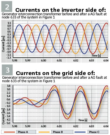
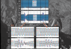
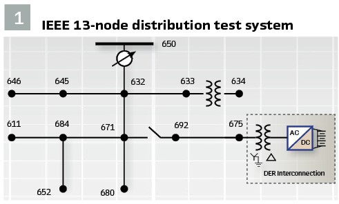
This behavior of inverters creates a problem with the traditional overcurrent-based fault detection. In the case of a three-phase interfacing transformer, a utility can choose a wye-grounded (YG) winding configuration on the grid side with delta (∆) winding on the generation side, which can provide a low impedance path to the zero sequence currents on the grid-side, and enable detection of unbalanced ground faults with the traditional overcurrent methods using appropriate thresholds for zero sequence currents. However, phase faults are not possible to be detected with only a current threshold. To illustrate this problem, a 480 V, 100 kW three-phase PV-connected inverter was modeled in PSCAD with a current limiter set at 110% of the rated current, and connected to node 675 of the IEEE 13-node distribution test system, shown in Figure 1, through a Δ-YG transformer. Inverter input was simplistically modeled as an ideal DC current source. A Line to Ground (AG) fault at node 633 was created at 6 seconds into the simulation. Figure 2 and Figure 3 show the currents at the grid side and inverter side, respectively.
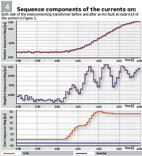
Notice that the inverter output current remains nearly balanced, positive sequence, and does not exceed 110% of the pre-fault value. On the grid side, the currents are unbalanced before the fault to provide the zero-sequence component in the load currents and increase substantially due to the large zero sequence current drawn by the AG fault. Figure 4 shows the per unit sequence components of currents on both sides of the interfacing transformer for the AG fault. Notice the negligible negative sequence currents on either side. The positive sequence currents increase according to the limit imposed by the current limiter, and the zero sequence currents on the grid side are governed by the unbalance in the circuit before and after the faults. Note that the stepped nature of the curves is caused by sequence-component calculation filters.
The results shown here assume the inverter operates at unity power factor before and during the fault. This can be different for inverters complying with LVRT requirements. In such cases, if short circuit analysis is performed on a microgrid fed by conventional sources and IBRs, the total fault current will be less than the scalar sum of the fault currents contributed by all sources. This is an unusual feature related to the short-circuit analysis of microgrids.
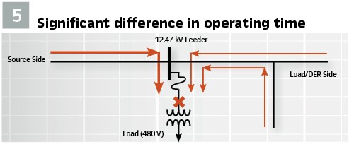
Maintaining Dependability for Grid-interconnected and Grid-isolated Mode: Typically, the substation source feeding a microgrid is a much stronger source of fault current compared to DERs within the microgrid. This is true even if the DERs are synchronous generators or induction motors. For example, consider a 1.5 MW, 480 V synchronous generator with a 15% sub-transient reactance, connected to a 12.47 kV grid through an interconnecting transformer of 5% reactance. For a three-phase fault at the interconnecting 12.47 kV bus, the generator would contribute 1/0.20 = 5.0 per-unit current based on its rating, which amounts to about 347 A at 12.47 kV. An induction motor of this size would contribute even less (typically 4 per unit) fault current in the first cycle. On the other hand, in a typical distribution feeder, the fault contribution from the utility source may amount to a few thousand amperes. Consider a scenario depicted in Figure 5, where a fuse is protecting a transformer feeding a radial load-feeder. This fuse will have to coordinate with the upstream source-side protective device as well as the upstream DER-side protective device. However, for a fault at the transformer (marked “X”), the operating time of this fuse in grid-isolated mode will be much longer than that in the grid-interconnected mode because of the large difference in fault currents flowing through the fuse.
Bidirectional Fault Current Flow: In microgrid systems, fault currents flowing through the system could be bidirectional due to multiple sources feeding the faults that occur in the utility system or inside microgrids. Due to the bidirectional fault currents, traditional non-directional devices like fuses, reclosers and overcurrent relays simply do not work. Even for directional protection elements, the off-nominal frequency of fault contributions from IBRs can challenge phasor determination. Additionally, the changing system frequency during faults while grid-isolated can challenge some directional determination methods. For faults in the utility-systems, a coordination between DER protection and Point of Common Coupling (PCC) protection is required if seamless formation of an island is of interest. For faults while grid-isolated, protection needs to operate quickly to facilitate a stable recovery (inertia mainly provided by synchronous machines). Additionally, if the DERs are capable of riding through these events, it may be desirable to set protective relays so that they do not operate for off-nominal frequency and voltage conditions. Tripping DERs offline during such an event can further challenge system recovery.
Utilizing Protection Relays to Detect Loss of Grid: Protective relays can be applied to detect when the grid is unavailable and initiate the transition from grid-interconnected to grid-isolated operation. In some cases, when the contribution from the microgrid to grid faults is very small and hence undetectable using the traditional protective elements like reverse power or directional overcurrent, a direct transfer trip from the utility side is employed to disconnect the microgrid for such intentional islanding. On the other hand, it is necessary to detect any unintentional islanding due to grid outages resulting from a system disturbance. In some scenarios, undervoltage, overvoltage, under frequency, over frequency, and/or rate of change of frequency protection can be used to detect this condition, but these may prove to be unreliable when generation in microgrid is enough to supply the load in the island. While reconnecting islanded microgrid with the grid, it should be considered that automatic reclosing can cause reconnection of two asynchronous, live systems.
The Impacts of Microgrid Control Strategy on its Protection: By definition, a microgrid system shall act as a “single controllable entity” from the grid perspective. The microgrid control system is typically designed to (i) reduce outage time of critical loads during all microgrid operating modes, (ii) decrease greenhouse gas emissions, and (iii) improve system energy efficiencies. Since the control results in changes in network topology and DER connection-status, it will impact fault profile and any protection depending on the fault profile.
Design Considerations
System impact studies, including short circuit analyses/equipment duty, overcurrent coordination studies, and transient stability studies should be performed to have a thorough understanding of the system’s protection requirements for different operating conditions. Additionally, the capabilities of the software tools should be thoroughly evaluated to make sure that the requirements of the studies can be achieved and that results are realistic. Using detailed EMTP models may have to be considered in case commercial software do not provide reliable results due to imprecise modeling of IBRs.
It is important to ensure that there is always a ground-source in any microgrid. In grid-isolated mode, this can be achieved by grounding the DER interconnecting transformers, or by providing a grounding transformer in microgrid, to cover the eventuality that interconnecting transformer(s) may be out of service. A reliable communication system for the microgrid is essential for control and protection related communications. Communication between the utility substation’s circuit breaker, the circuit breaker at the PCC, and the DER circuit breakers internal to the microgrid is often valuable; ideally, the communication system would interface with other protective devices of the microgrid as well.
Protection Scheme Solutions
As explained in Section 2, due to the unique operating and fault characteristics of microgrids, the conventional protection and control schemes may not always meet the requirements. To cope with these issues, some customized logics or schemes have been put into practice or consideration. Some of these are summarized now.
Negative and Zero Sequence Overcurrent: As described before, due to the fluctuation in the maximum fault current level, the conventional phase overcurrent may not be sensitive enough in the grid-isolated mode. Therefore, the negative and zero sequence currents may be used to detect asymmetric faults, if significant amount of negative and zero sequence currents can be generated. The pickup thresholds can be based on their absolute magnitude or relative change over the positive-sequence current. If fault currents are limited by IBRs, there may not be enough negative-sequence current to be used for protection purpose. It should be mentioned that sequence-based protection schemes can be difficult to coordinate and may require additional protective functions for symmetrical faults.
Under-Voltage Protection Schemes: A fault within an islanded microgrid can result in a network-wide voltage drop, which could be utilized to detect faults. Although the under-voltage-based methods (27) are independent of the value and/or direction of the fault current, the network voltage can be affected by various transient incidents other than faults, such as load switching and/or energization of dynamic loads. More importantly, under-voltage-based methods cannot provide adequate selectivity due to inefficient coordination.
Voltage-Restrained and/or Voltage-Controlled Protection Schemes: Voltage-restrained (51V-R) and voltage-controlled (51V-C) OC protection provides improved sensitivity of OC relaying by making the pickup setting values proportional to the applied voltage. This helps overcome the problem of low fault currents. The disadvantage is that the coordination of these relays for microgrid applications is still problematic as they are supposed to operate for a wide fault current range.
Adaptive Relay Settings: Adaptive protection system is a real-time, online activity that modifies the preferred protective response to a change in system conditions, business rules, or forecasted reconfiguration in a timely manner by means of externally generated signals or control actions. One significant issue for the adaptive relay settings approach is that the protection may become inoperative momentarily while settings are being changed.
Transfer Trip Signals and Operating Status: Direct transfer trip protection schemes use communication to provide trip signal(s) from one protection device/system to other protection devices and/or the microgrid protection system. This is commonly utilized with distributed generation to prevent unintentional islanding, for breaker failures, and for bus or transformer faults where multiple sources can contribute to the fault. In microgrids, a transfer trip signal may be sent from devices such as the feeder breaker or feeder recloser to the microgrid protection systems, to avoid unintentional island or continued contributions to faults. In addition, operating status signals can be sent from the microgrid protection systems to the feeder IED for adaptive feeder protection, or for permissive signals for closing the feeder breaker or recloser, or for annunciation of the microgrid protection system’s status to operators.
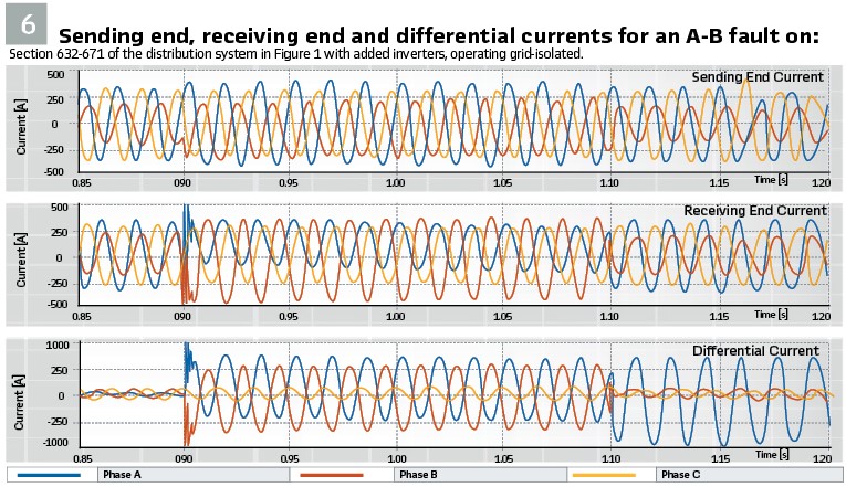
Current Differential Protection: If the communication infrastructure is well planned and fiber optic channels are available in a microgrid network, the communication-based line differential protection can be applied as the primary protection, since the low voltage created at the fault point will dictate that current flows into the faulted feeder from both ends, no matter the operating mode. Figure 6 shows the effectiveness of the differential principle in an extreme scenario of the highly unbalanced distribution system shown in Fig. 1 being in grid-isolated mode, and fed only by IBRs connected to buses 650 (2.08 MW), 692 (1.55 MW) and 680 (1.55 MW), each restricted to provide no more than 1.1 pu of its rated current. Phase A to B (A-B) fault is simulated on feeder 632-671 at 0.9 s into the simulation. Clearly the differential current is significantly high during fault, although the fault currents increase marginally compared to load currents.
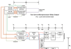
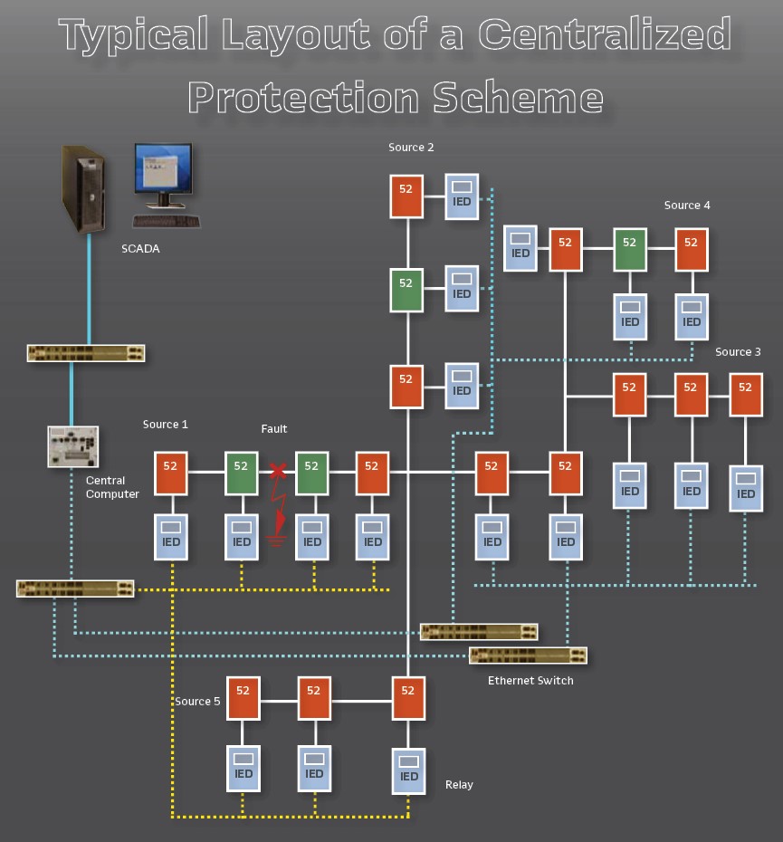
Centralized Protection System: A centralized fault detection system that uses the fault information from multiple sensing devices located throughout the power system may allow for more accurate determination of the fault location or section, so the fault can be quickly isolated, and outage areas can be minimized. Furthermore, the restoration may be done quicker using data from IEDs at different location along with Faulted Circuit Indicator data from many locations.
Since all necessary information such as system topology, breaker status, power generation, load distribution, real time voltage, and real time current is available at a central controller, it makes sense to integrate fault detection, isolation and restoration into the same package to optimize the entire process. First, the communication network must be set up so that the central computer is able to collect the information from all protective relays or other Intelligent Electronic Devices (IEDs) in the microgrid and to issue commands to all relays or IEDs that control circuit breakers. Two approaches can be employed. In the first approach, a fault can be isolated by local protection, reporting the breaker status to the controller, where the backup protection is integrated. In the second approach, both main and backup protection are integrated with the controller. The second approach relies more heavily on high-speed and reliable communication between sensors, breakers and controller. A layout of a centralized protection scheme is presented in the Figure.
Conclusion: Integration of microgrids with the power system presents an opportunity to improve power system reliability and resilience. From the various potential solutions summarized in this article, a solution should be chosen that offers an acceptable combination of reliability and the cost of infrastructure required for the solution. More solutions may emerge with advances in sensor technology, combined with better communication and computing resources.
Biographies:

S.S. (Mani) Venkata is President of Venkata Consulting Solutions Inc. He was with GE Power/Alstom Grid Inc. from January 2011 to September 2017. He continues his affiliation with the University of Washington (UW), Seattle, Washington where he has taught since 1979. Dr. Venkata is a Life Fellow of the IEEE. At the IEEE level, he served as a member of the IEEE Fellows Committee for five years. He also served on the PES Board as Vice-President, Publications PES during 2004-07. In 2016 he received the Robert M. Janowiak Outstanding Leadership and Service Award from ECEDHA. In 2015 he received the IEEE PES Douglas M. Staszesky Distribution Automation Award. In 1996 he received the Outstanding Power Engineering Educator Award from the IEEE Power Engineering Society.

Sukumar Brahma received B.Eng degree from Gujarat University, MTech from IIT Bombay and PhD from Clemson University, all in Electrical Engineering. He is Distinguished Professor in Power Engineering and Director of CUEPRA at Clemson University. Prior to this, he was William Kersting Endowed Chair Professor at New Mexico State University. He is a Distinguished Lecturer and Fellow of the IEEE and has served as an editor and a guest editor-in-chief for IEEE Transactions on Power Delivery. As PES volunteer, he has chaired Power and Energy Education Committee, Distribution System Analysis Subcommittee, and is a member of Power System Relaying and Control Committee. His research spans across diverse areas of electrical engineering and computer science to holistically approach the emerging problems in power system protection.