By Adriano Oliveira Pires and Hector Leon, GE Renewable Energy, Brazil, Leandro de Marchi Pintos (Brazil), Patrick Montaner (France) and Chee-Pinp Teoh (UK), GE Renewable Energy
In the context of full digital substations, which includes the capability to exchange voltage and current data in between IEDs in real time over network through Sampled Values protocol, the substations started to be segmented into process and station level, in which interface IEDs, usually responsible to digitize binary and analog data or to Interact directly with primary equipment are now positioned on the yard, cumulating advantages related to cable reduction, civil infrastructure, cost, simpler installation and safer when using fiber optic.
To enable full digitalsubstations and all its advantages interfaces are needed at process level being responsible for data modeling and acquisition of primary devices and to physical activation of controls computed at station level.
Among these interfaces it can be highlighted:
- Merging Units (MU) or Stand-Alone Merging Units (SAMU), converting voltage and current signals into synchronized data streams through IEC61850-9-2 standardized protocol.
- Switchgear Interface Units (SIU) and Remote I/Os (RIO), as interfaces for status and control binary signals for Circuit Breakers and switches.
- Non-Electric Interface Units (NEIU) as interface for non-electrical data that can be monitored through transducers and be shared through GOOSE, MMS or Sampled Values, for example.
- Process Interface Units (PIU) as a single IED capable to perform all the functions above mentioned.
Being PIU the device capable to perform several functions, it may be modeled and developed in different ways, but in the perspective of architecture and installation of full digital substations it has the fundamental characteristic of being a single IED, ideally placed in the process level, on the yard and near to primary equipment, as the interface in between physical and digital worlds which brings advantages analyzed in this paper.
Substituting two or more IEDs by one PIU implies the possibility of convergence of components like the chassis, power supply, processing cards and communication modules, allowing to perform the same group of functions with less footprint for the total solution, reducing costs and at the same time adding reliability, since the probability of failure for total system is reduced along with the reduction of subcomponents in the solution.
On top of the advantages mentioned above, an architecture based on PIUs also means a reduced number of devices to be submitted to commissioning and testing processes, consequently reducing the footprint, total installation cost and time during the commissioning process.
Same principle might be considered for other departments including operational costs reduction, once there are less assets to be managed and maintained, and better management of spare parts.
A study based on comparison of hypothetical devices with market standard characteristics is presented to analyze quantitative and qualitative advantages for full digital substation architectures based on multiple IEDs against a single PIU as interface for primary equipment.
It is also presented how PIUs can be logically modelled using the base concepts of the IEC61850 standard to segregate functions into logical devices and allowing to decouple logical and physical devices, simplifying architectural decisions for both cases.
It is concluded that PIU as single interface IED has advantages as smaller footprint and cost and higher system reliability. All mentioned advantages are maximized when the substation architecture considers redundancy of devices, common for critical parts of the electrical system, pointing to the use of PIUs as a tendency for modern full digital substations.
Basic Process Level Interfaces and Applications
Merging Units (MU) and Stand-Alone Merging Units (SAMU): Merging Units (MU), according to the IEC 61850-2, is a physical unit that perform a time coherent combination of voltage and/or current data coming from secondary converters, that can be from different types of transducer, and publishing them in Sampled Values format.
A Stand-Alone Merging Unit (SAMU) is defined by the IEC61869 as a particular and most common type of Merging Unit capable of handling standardized inputs from conventional voltage and/or current instrument transformers, capable to be used in green or brown field.
Such device can be modeled as presented in Figure 2 with a BASE logical device (LD) with base functions for most of the devices and a MU logical device to model the decentralized analog acquisition.
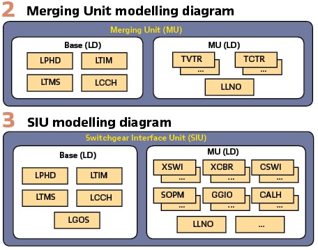
For base functions are highlighted the ones modelled by the logical nodes LPHD (physical device information), LCCH (physical communication channel supervision), LTIM (time management) and LTMS (time master supervision)
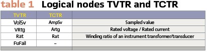
The decentralized analog acquisition is modeled through the logical nodes TCTR (Current Transformer) and TVTR (Voltage Transformer), that models the interaction with the instrument transformers including data objects as on Table 1.
Voltage and current values are sampled at a configurable sample rate and then sent through Ethernet using the Sampled Values (SV) protocol to the subscribers to process these data. Using the decentralized acquisition is possible to use relays not physically wired to the current transformers (CTs) and voltage transformers (VTs), it can be possible to share the acquisition among relays and other monitoring devices without overloading transformers as well as add other devices with no change on the wiring.
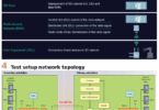
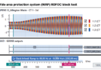
With advanced cross-checking function, the relays and monitoring device can compare 2 sampled values streams for better dependability. In the case of sampled values stream failure, the relay and monitoring devices have the flexibility to automatically switch the sampled values subscription to the healthy one for higher availability (Figure 6 a). Decentralized acquisition provides greater flexibility and reliability in the event of failure.
For SV subscribing, the standard IEC 61850 defines that both subscriber and functions that will use these signals declare it as external reference. It allows other tools to check the equipment configuration files and identify the data flow within the substations.
Switchgear Interface Unit (SIU): A SIU can be defined as the device that provides binary status and control interface for circuit breakers and switches, including the main logical nodes and behaviors interacting with this equipment.
There are products from various vendors that extend the above concept by adding capability to perform simple logics, interlocking, CB control and act as Remote I/O (RIO), interacting with other generic I/Os in the process.
Such device can be modeled as presented in Figure 3 with a BASE logical device and a SIU logical device to model the interfaces with switchgears and other generic I/Os.
For base the functions are modeled the same logical nodes as in a Merging Unit with the addition of the LGOS (GOOSE supervision), since the SIU should be able to subscribe to GOOSE messages and should be able to use it to activate physical binary outputs.
The interface with switchgear can be modelled by logical nodes like XSWI (Circuit Switch), XCBR (Circuit Breaker), CSWI (Switch Controller) and SOPM (Supervision of Operating Mechanism), generic I/Os can be modelled by LNs like GGIO (Generic I/O) and CALH (Alarm Handling).
Other modelling variants consider extra logical nodes with direct interaction to binary I/Os in the process level, for example through logical nodes as YLTC (Tap changer) or CILO (Interlocking).
Non-Electric Interface Unit (NEIU): A NEIU can be defined as the device that provides interface for different types of non-electric sensors, converting them to time synchronized streams of Sampled Values or GOOSE.
A variant of this concept admits that these units can use thresholds and logics to convert measured values into binary information. An example of this application can be a gas pressure sensor having thresholds to set PresAlm (Pressure alarm) in a certain SIMG (insulation medium supervision – Gas) instance.
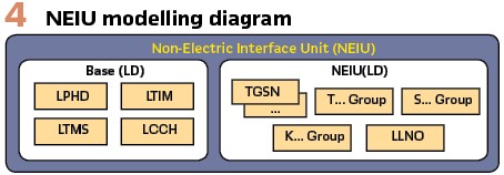
Such device can be modeled as presented in Figure 4 with a BASE logical device and a NEIU logical device to model the interfaces with transducers and other non-electric sensors.
For base functions are model the same logical nodes than in a Merging Unit.
The interface with non-electric sensors can be modelled by different logical nodes from groups T (Instrument transformers and sensors), S (Supervision and Monitoring) and K (mechanical and non-electric primary equipment). TSGN logical node is highlighted to model generic sensors.
Process Level Interfaces Architectures
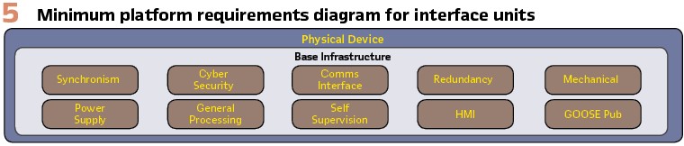
All basic applications and interfaces described earlier are hosted in hardware platforms and deployed in full digital substation as physical devices with minimum base infrastructure, as represented in Figure 5.
Physical devices, functions and logical devices can be organized into different architectures to accommodate the interfaces applications above mentioned.
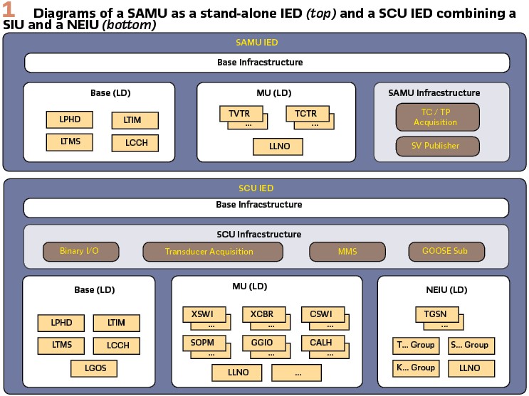
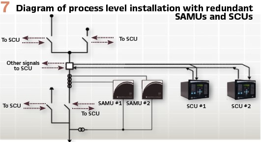
Multiple Boxes Architecture – SAMU + SIU + NEIU: For a multiple boxes’ architecture two or more IEDs are needed to perform the applications mentioned earlier. In this article the focus is a common variant of this architecture composed by two physical IEDs as presented in Figure 1 where:
The SAMU as a stand-alone IED covers the Merging Unit application, requiring additional infrastructure to handle analog acquisition and sampled values streaming
The Switchgear Control Unit (SCU IED) covers SIU and NEIU application, requiring support to MMS, GOOSE subscription, binary I/O acquisition and control and transducer acquisition
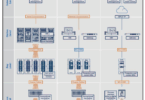
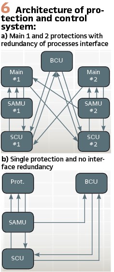
Depending on the substation and its reliability requirements the installation of these interfaces can be different. In a substation where high availability is required a bay can typically have the architecture on Figure 6 a) where there are main 1 and 2 protection devices connected to redundant SAMUs and SCUs, ensuring that each important connection will have a fallback and all signals will be shared with protection and control devices. In other substations where cost is more critical a bay can typically have the architecture on Figure 6 b) with a single protection device and one set of SAMU plus SCU as process interface.
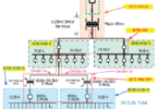
Considering the architecture with higher availability (see Figure 6 a) an installation on process level for a line bay follows the represented in Figure 7 where the SAMUs are wired to TPs and TCs while the SCUs handles all the binary I/Os and Non-electric signals.
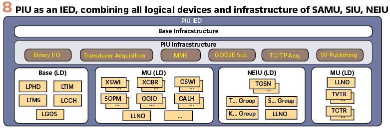
Single Box Architecture with a Process Interface Unit – PIU: In a Single Box architecture, a Process Interface Unit (PIU) is required to combine in a single IED the capabilities of the three main interfaces applications mentioned earlier, as represented in Figure 8. This IED is completer and more complex than the before mentioned, since it must comprise of all logical modelling and infrastructure to handle the complete set of process level interfaces, therefore acquire electric signals from TCs and VTs, non-electrical signals from transducer and monitoring and activating binary I/Os.
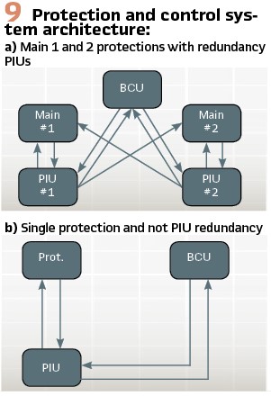
Similarly, what is presented earlier, the solution with PIUs in a full digital substation will depend on the reliability requirements. In a substation where high availability is required a bay can typically have the architecture on Figure 9 a) where main 1 and 2 are connected to redundant PIUs in a way that all important connections have a fallback and signals are shared with protection and control devices. Where cost is more critical a bay can typically have the architecture on Figure 9b) with a single protection device and a single PIU.
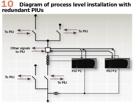
Considering the architecture with higher availability (Figure 9 a) the installation of a line bay follows the represented in Figure 10 where simply the PIU will monitor all signals.
Comparison Study for Process Level Architectures
The comparison of the process level architectures considers different quantitative and qualitative parameters with a vendor agnostic approach, therefore some variables such as costs and MTBF are defined in relative terms for supposed generic devices with the characteristics described earlier.
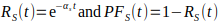
For all comparison it can be considered the three hypothetical devices with the parameters defined in Table 2.
Where cost is estimated in a fictious cost unit ( $) based on various market prices and the infrastructure needed for each type of device. It becomes evident that the PIU is the costliest device, since it requires to handle all interfaces and services in a single platform, but cost is not the direct summation of a SAMU plus SCU, since these two share a base structure that doesn’t need to be duplicated as a PIU.
MTBF and MTTR were hypothetically defined as the same for all IEDs. Availability can be defined as:
| 1) |
For all analysis it is considered four architectures:
- Architecture 1: A bay with installation based on Figure 6 a) with redundant process interfaces (two SAMU and two SCU)
- Architecture 2: A bay with installation based on Figure 6 b) with one SAMU and one SCU
- Architecture 3: A bay with installation based on Figure 9 a) with redundant PIUs at process level
- Architecture 4: A bay with installation based on Figure 9 b) with one PIU
Material Cost: The material cost comparison presented in Table 3 simply considers the type and quantity of devices for each architecture. The hypothetical costs are taken as reference and a percentage cost reduction is estimated compared to the most expensive scenario, which is the Architecture 1.
MTBF, Availability and Reliability: MTBF and Availability analysis in composed follow two principles:
If two sub-systems/devices A and B need to be both operational for the system be operating it is considered that they have a series dependency. In this case the systemic failure rate (S) is the linear combination all subsystems failure rate (x)
| 2) |
If two sub-systems/devices A and B are redundant and only one of those needs to be operational for the system be operating it is considered that they have a parallel dependency. In this case the systemic failure rate (S) is given by:
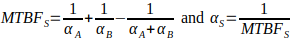 | 3) |
Additionally, it can be determined the Reliability (Rs) of each system over the years which is considered to decay exponentially over time by the equation 1. The Probability to Failure (PFs) is the inverse of Reliability and can be calculated based on the difference:
 | 4) |
In the case of the analyzed architectures the composition is given by:
- Architecture 1: It is composed by two parallel/redundant subsystems. Each subsystem has a series dependency of two devices
- Architecture 2: It is composed by a series dependency of two devices
- Architecture 3: It is composed by two parallel/redundant subsystems. Each subsystem is composed by a single device
- Architecture 4: It is composed by a single device
Systemic Availability, MTBF, Annual Failure Rate and Probability to failure over time are given in Table 4.
General Comparison: Material cost and general reliability are important parameters to analyze and compare each architecture, but although they are clearly quantitative there are many other points to be considered in a complex comparison like this.
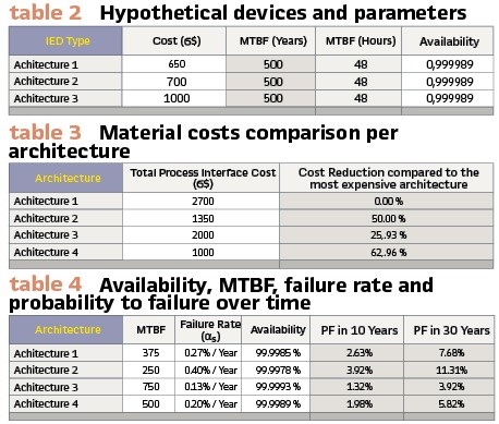
In the scope of this paper the below parameters will be considered for each architecture and a score from 1 to 4 is given where 1 is the worst and 4 is the best score among the scenarios analyzed. The parameters and their descriptions are:
- General Reliability, based on the described earlier
- Material costs, based on the described earlier
- Installation and commissioning, considering installation and commissioning efforts
- Operational costs, considering overall operational costs including asset management needs
- Spare management, considering the easiness to manage spares
- Vendor dependency, considering the minimum part of the solution that can be given to a single vendor.”
- Footprint, total footprint for the solution
- Complexity, total logical complexity considering to integrate/recommissioning new Protection and Control IEDs.
- Flexibility, capability to use and change different subsystem without interfering the other pieces.
Table 5 summarizes all scores for the considered parameters.
Although these scores cannot be directly connected to the concept of what is the best architecture in full digital substations, it provides a good overview of the comparison in between the discussed architectures and helps the user to quickly identify the best one for a certain parameter.
For most of the parameters the architectures based in PIUs, single or with redundancy, have better score, highlighting advantages regarding reliability, cost, footprint and overall simplicity, which can be associated to the fact of reducing the number of failure points in the system and converging base infrastructure, services and logical nodes that are needed regardless the type of application in an IED ready for full digital substations.
Architectures based in a combination of IEDs for process level interfaces brings more complexity and parts to be installed and maintained, but at the same time they bring more flexibility allowing that more diversified vendors or products composes the solution and bring freedom that different teams or processes manages the different types of interfaces.
Biographies:

Adriano Oliveira Pires is a Product Manager at GE Grid Automation, responsible for the portfolio of Digital Fault Recording, Traveling Waves Fault locator and Process Interface Units. Has experience in these product lines since 2012, starting at Reason Tecnologia S.A., in Florianopolis, Brazil. Is graduated in Electrical Engineering by the State University of Santa Catarina and has his master’s degree by the Federal University of Santa Catarina.

Hector Leon is R&D Application Engineer at GE, Holds Msc in Electrical Engineering from Universidade Federal de Santa Catarina in Brazil. His main interests and research fields include Communication Protocols and Networking for Substation Automation Systems as well as Systems and Application Architecture for smart grids solutions.

Leandro de Marchi Pintos is Application Engineer at GE Grid Automation in the area of Global Application and Support for the Reason Product Line. Has experience since 2014, starting at Reason Tecnologia S.A., in Florianopolis, Brazil and also has experience with protection and control equipment. He graduated in Electrical Engineering from the Federal Technological University of Parana and has a master’s degree by the Federal University of Santa Catarina.

Patrick Montaner is a System Application Architect at GE Grid Automation, responsible to create reference architectures, solution strategies. Has experience since 1999, starting at Alstom, in Montpellier, France, through developer to architect in both protection and bay controller areas. He graduated in Electrical Engineering.

Chee-Pinp Teoh is Senior Product manager – Digital Substation Solutions in Stafford, UK. He has a B.Eng (Hons) and MBA. He is also a Senior Expert under GE Expert program, a registered Professional Engineer, member of The IET, corporate member of IEM, UK representative for CIGRE B5 WG.