by Walter Schossig, Germany, and Thomas Schossig, OMICRON electronics GmbH, Austria
After the introduction and the first details in the first article, we will continue with more details on the testing.
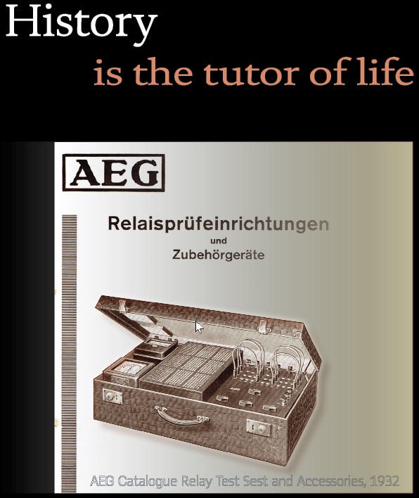
It was obvious, that powerful testing devices have been needed to check measurement transformers, protection relays, and primary tripping devices. After mounting the device, when the relay could be damaged or smutted, and during the commissioning a detailed test was mandatory. All the single parts of the protection system had to be tested: wires, captions of plugs, measurement transformer wiring, and all the single protection elements (directional, measurement, supervision, …) When putting into operation distance relays and directional relays, the rotating field and its indication had to work properly. Also, the direction of winding should be checked. The goal was to have unitary mounting of the current transformers. The busbar’s side was marked with “K“ and “k” (earlier L1 and l1) . Earthed on the line’s side was marked l (earlier l2). Using the wiring diagram all details have been checked and marked. After this all the settings had to be checked. The best test at this time was the start with built in primary fault. If such a powering was not possible, a primary test as described in Figure 1 was necessary.
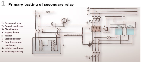
The so-called n-relays (resistance dependent) had to be checked during commission mainly on time grading. Some points of the characteristic have been sufficient. This was done via secondary test. In case of problems found, the relay was changed and received maintenance in the lab.
Relays, where the time was depending on phase-angle had to be tested as well (Figure 2).
Directional elements could be tested with operating current. The precondition is the detection of direction of power. In mashed grids this required star operation and watt-metric measurement. Relays by Dr. Paul Meyer (new release), S&H-distance relays and reverse current relays by AEG and S&H have been connected with their directional elements to the voltage permanently. AEG, BBC relays as well as V&H ring protection and the older relays by Dr. Paul Meyer had to be connected to the voltage manually. In case of doubts there was the recommendation to reconnect the voltage several times and check the results as crosscheck.
As control devices mainly rheostats have been used. Only for very important stations the rheostats have been replaces by regulating transformers. The test sets could be mounted or portable (equipped with wheels).
So, at the beginning of the 1930s AEG offered a wide range of testing devices with accessories.
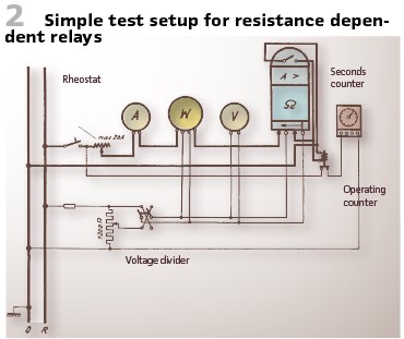
Figure 3 shows the typical “suitcase.”
The German word for suitcase is “Koffer” and still used today to describe testing equipment in a box. Such a test set in suitcase could be used for secondary testing of voltage and current relays. Additionally, single phase test of distance relays was possible as well, but only if the phase shift between voltage and current was not considered. The current was taken from the low-voltage grid and switched by a 2-pole breaker. The control of the current was again via a rheostat (three-part). This method was very beneficial to test current dependent relays, where the operating time depends on current’s waveform. Because of the inductive control the current was distorted very often. An ammeter, for DC and AC, voltage range 0…10 A and 0…20 A visualized the current value. The testing voltage was available at voltage divider, the voltmeter with two ranges (0…130 V and 0…260 V) showed the value. Additionally, the system was equipped with seconds counter and three-pole switch connecting the seconds counter and taking into account if the contacts have been wet or dry.
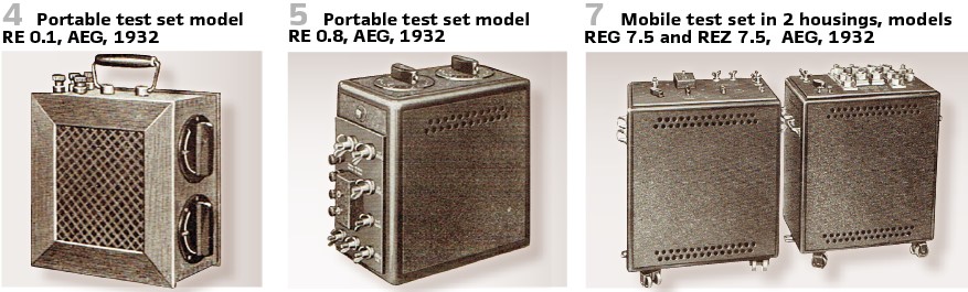
The portable devices (Figure 4 and Figure 5) with their power could be used to test meters, tripping devices and protection with transformers. The maximum current was 3000 A. The size was small, and the devices have been easy to use. They mainly consisted of regulating transformer and high-current transformer. The regulating transformer was an autotransformer and connected to the 110 V, 220 V or 380 V grid (selectable) via 4-pole breaker and fuses.
The control was possible via two step controllers, a raw and a fine tuning in 20 steps each possible so in sum 400 steps could be controlled and made the control very precise even in case of low currents. At the secondary voltage of the autotransformer the primary side of the high-current transformer is connected to. Several stages of voltage have been offered. The normal steps have been 4, 8, 40 and 250 Volts. One stage even could be set to 2 V. A diagram showed the maximum load currents taking into account power and voltage. For 5 minutes it was possible to deliver three times the permanent current. The seconds counter could be connected as well.
Everything was in a stable steel metal case, equipped with handles. Devices with the label REW came with built in measurement transformer for secondary current of 5 A. Every information was engraved on the case (Figure 5).
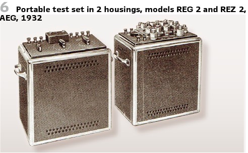
For higher testing power devices in 2 housings were also available (Figure 6, Figure 7).
Main device and auxiliary devices have been in different boxes. This allowed easier transportation. The high-current transformer in the auxiliary box could be mounted close to the relay transformer. The control could be done close to the relay itself. The short connection cables allowed operation even with lower voltage.
The main device consisted of voltage transformer, switch and three inductive controllers (raw, medium, and fine). The high current transformer is primary made for 220 Volts. On the secondary side there are several coil groups. Splice bars allowed several connections and so different combinations of voltages and currents.
In the auxiliary housing we find the high-current transformer and current transformer for measuring (nominal current 5 A). In case of switching the primary side of this transformer, the measurement ranges are switched as well. A switch on the secondary side increased the amount of measurement ranges. Of course, the switchover had to be done without interruptions.
The main device could be used also without the auxiliary one. For the measurement of the current additional measurement transformer was required in this case.
AEG also offered portable test sets in 2 housings with phase shifter. Those devices allowed testing power relays as well as angle-dependent distance relays. They consisted of main device and auxiliary device (Figure 8).
The auxiliary device was the same as for the test sets without phase shifter. The main device required three-phase alternating current power supply (3x 110 V, or 2x 220 V , or 3×380 V). It consisted of voltage circuit and current circuit. The voltage circuit was powered by the grid via fuses. The arrangement of the voltage vector could be set up at the phase shifter via crank handle. A mechanical indication visualized the phase shift. The phase shifter was designed for permanent power of 180 VA with a secondary nominal voltage of 125 V without CR. An additional fine tuning was possible with inductive controllers between 0 and nominal value.
The current circuit was connected via special breaker to two phases of the voltage circuit. Two changeover contacts within the current circuit could control the voltage circuit in such a manner, that distance protection could be tested easily. Before testing the relay, the normal voltage was supplied. When the current was switched on, another voltage was delivered and so all fault conditions in terms of voltage and current could be delivered to the relay.
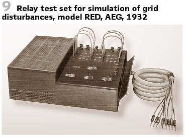
The relay test sets of AEG could not be used for testing the relays with shots, but even emulate disturbances in the grid. So, there was a special equipment available, allowing to test relay sets consisting of several distance relays. It consisted of 3 variable resistors, simulating the phase impedances of the line.
A two-pole and a three-pole breaker could simulate the different fault conditions, including short circuits and doubled earth faults. The current value could be controlled at the resistances. Relay’s voltage could be taken at the resistance with any value between zero and nominal value. The test set had plugs to connect seconds counter and an ammeter.

All cables have been equipped with unique connectors; the corresponding plug was on the relay table. An additional changeover switch allowed to change from operation to test mode. There was no additional wiring necessary during the test. An additional test terminal block was optional. Figure 9 shows the device.
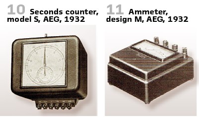
As mentioned already, there have been accessories available. To measure relay’s operating time the seconds counter (Figure 10) was the choice. It contained small synchronous motor, connected to the pointers at the beginning of the measurement.
This connection will be opened once the relay tripped, and the movement of the pointer stops. The start-up time of the motor was not used to increase the accuracy of the measurement.
As measurement devices the ammeter (Figure 11) could be used.
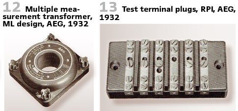
Every other ammeter could be used as well. If a current transformer was needed, AEG offered the multiple high accuracy measurement transformer design ML, Figure 12.
Also, nice carrying bags have been available, made of calf leather.
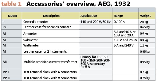
Test terminal blocks as shown in Figure 13 made the testing easier. Switchover between normal operation and testing was possible without additional wiring, Grid’s current transformer have been short-circuited, the relay was disconnected from the voltage transformer.
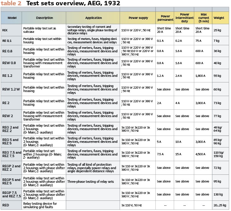
For completeness and to illustrate the product portfolio Tables 1 and 2 summarize accessories and test sets available.
After this long chapter covering testing of protection in Germany during the early 1930s, we are watching what happened in the US at this time as well.
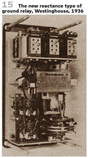
Goldsborough and Smith (both with Westinghouse) published a paper on” A new distance ground relay” at A.I.E.E. in 1936. The theory and the design of a new distance relays suitable for ground protection have been described in this article.
Extensive field tests could be reported. Distance relays have already been common practice at this time. New high-speed relays have been introduced already. From the standpoint of reliability, ground faults have to be cleared as rapidly as phase faults, their preponderance and the danger of their developing into phase faults if not quickly cleared, makes desirable the application of the distance principle to this kind of fault.
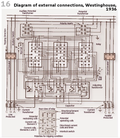
The new reactance type of ground relay, Westinghouse, 1936. Figure 15 shows the relay, Figure 16 the connections.
Extensive field tests have been conducted to prove the theory and the operation of this relay. These tests covered a wide range of conditions both in regard to the line characteristic and the general system characteristic. The first group of tests was conducted on a pair of 110 kV lines if the Carolina Power and Light Company. These lines are located near Raleigh. N.C, and are approximately 25 miles long (Figure 14, Figure 17).
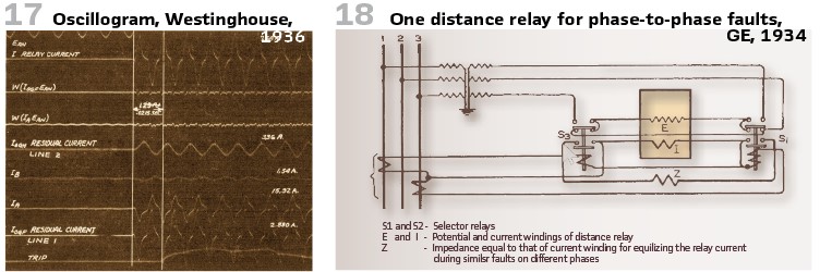
At the end of this article, we want to mention another interesting approach. Warrington, who was with GE in Philadelphia, published a paper “Control of Distance Relay Potential Connections” in 1934. By means of the automatic switching of potential connections to distance relays according to the type of fault, each distance relay may be made to do the work of 2 or 3 of such relays.
The cost of distance relay installations may be reduced considerably by this automatic control potential connections, and consequently their use should become more widespread.
In Continental Europe, distance relays enjoyed a much wider popularity than in the U.S. and so the author made this proposal.
Figure 18 shows as an example the arrangement, using one distance relay instead of 3 for faults between the phases. In order to prevent operation normally while the potential circuit of the distance relay is short-circuited, it should have a starting unit which cannot operate on current alone. The distance relay will be energized for faults between the various phases. It will be noticed that a fault between the phase 1 and 2 or a 3-phase fault provides current from both the current transformers, but the distance measurement is kept the same by bypassing half the current through the “impedor Z.”
info@walter-schossig.de www.walter-schossig.de
thomas.schossig@omicronenergy.com
Biographies:

Walter Schossig (VDE) was born in Arnsdorf (now Czech Republic) in 1941. He studied electrical engineering in Zittau (Germany), and joined a utility in the former Eastern Germany. After the German reunion the utility was renamed as TEAG, Thueringer Energie AG in Erfurt. There he received his master’s degree and worked as a protection engineer until his retirement. He was a member of many study groups and associations. He is an active member of the working group “Medium Voltage Relaying” at the German VDE. He is the author of several papers, guidelines and the book “Netzschutztechnik [Power System Protection].” He works on a chronicle about the history of electricity supply, with emphasis on protection and control.

Thomas Schossig (IEEE) received his master’s degree in Electrical Engineering at the Technical University of Ilmenau (Germany) in 1998. He worked as a project engineer for control systems and as a team leader for protective relaying at VA TECH SAT in Germany from 1998 until 2005.
In 2006 he joined OMICRON as a product manager for substation communication products. He is author of several papers and a member of standardization WGs.