(Based on Power System Relaying Control Committee Report of WG C32 of the System Protection Subcommittee)
by Mukesh Nagpal-chair of the PSRC WGC32 of the SP Subcommittee
PSRC WG 13:
Chair – Mukesh Nagpal,
Vice Chair – Mike Jensen,
Secretary – Michael Higginson
PSRWG 13 Members:
Abu Bapary, Jeff Barsch, Michael Bloder, Sukumar Brahma, Duane Buchanan, Ritwik Chowdhury, James Deaton,
Randy Cunico, Alla Deronja, Rui Fan, Evangelos Farantatos, Kamal Garg, Yanfeng Gong, Frank Gotte, Jean-Francois Hache, Ali Hooshyar, Addis Kifle, Hillmon Ladner, Bruce Magruder, Jezze Martinez, David Morrissey, Krish Narendra, Andrew Nguyen, Manish Patel, Nuwan Perera, Joe Perez, Dan Reckerd, John Seuss, Jim van de Ligt, Amin Zamani
Rapid growth in interconnection of solar photovoltaic, battery storage and Type III or IV wind energy conversion sources to the transmission system is creating new challenges for protection engineers. These energy conversion sources connect to the grid with full or partial power electronic interfaces that are referred to as inverter-based source or IBR for convenience in this article. Protection challenges are introduced because the output current of an IBR facility is very different from a traditional rotating synchronous source facility during short circuit conditions.
This article is a condensed version of the report which describes in detail protection challenges associated with interconnection of IBR facilities, suggests solutions, and documents lessons learned from the present limited experiences thus far. The goal of the report is to provide a resource to assist protection engineers in the successful integration of IBR to the electric power grid using relaying devices available in the marketplace.
New Challenges
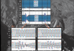
New challenges to the traditional line protection schemes from interconnecting IBR facilities are highlighted with the help of recorded real-world fault data of an internal phase-to-phase fault (A-to-C) on a short 138 kV line interconnecting a 100 MW Type IV wind turbine facility to the integrated grid. Figure 1 shows the short circuit current waveforms captured by the line protection relays. These waveforms were filtered by a 60 Hz bandpass filter within the line relay design. The left plot is three-phase current from the relay looking into the line and operate on short circuit current supplied by the integrated system to the fault. Likewise, the right plot is recorded data from the relay operating on short circuit current supplied by the wind turbine facility.
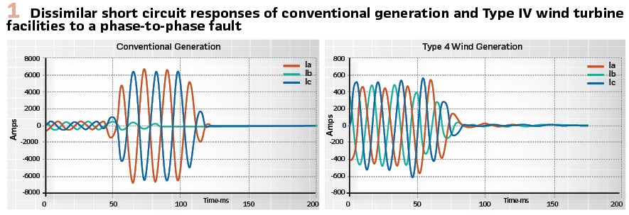
Prior to the fault, the wind facility was exporting rated power output at unity power factor. The short circuit current from the integrated system, comprised of many interconnected synchronous generators, was as expected. The currents in the two faulted phases increased significantly from the pre-fault 420 A to more than 6000 A during the fault. The line distance relay (Zone 1) correctly operated and tripped the breaker within four cycles. However, the controlled short circuit response of the wind turbine facility was significantly different. The short circuit current from the wind turbine facility did not increase at all on fault inception and thereafter. It remained at its pre-fault level and then started to rapidly drop after about two cycles into the fault becoming almost zero around the end of the third cycle. In this case, the IBR could be essentially viewed as a source whose internal impedance rapidly increased and became an open circuit in about three cycles after the fault inception. The protection application engineer was not familiar with the specific control system used in the facility and did not anticipate the short circuit response as observed. Thus, the traditional line distance protection scheme applied at the wind terminal did not respond to this phase-to-phase in-zone fault.
The waveforms presented illustrate the significantly different short circuit response of an IBR compared to the integrated system or clusters of interconnected conventional synchronous sources. They highlight that the reliability of traditional line protection schemes, operating solely or largely on short circuit current contributions from IBR facilities, can be at risk without additional measures. Furthermore, the IBR facilities do not respond to unbalance voltages like a conventional synchronous generator whose windings are low impedance for unbalance current and allow negative sequence current to flow into the line.
But most modern inverter control systems block unbalance currents which in turn, block flow of negative sequence current from the IBR facility into the line.
Negative Sequence based Directional Ground Fault Relaying
The intent of this section is to discuss the measures in conventional line protection schemes to counter low-magnitude or uncertainties in characteristic of the short circuit current, in particular lack of negative sequence current, from IBRs during ground faults. Only two examples of recorded short circuit currents and voltages on the lines supplied by IBRs are used. More examples are in the report confirming the similar findings.
Example 1–Type III Wind Turbine Generator: Figure 2 shows the 230 kV single circuit transmission system between the integrated system of utility at station (ISTN) and a remote transmission station (RTLR).
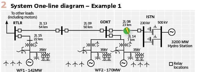
System Description: ISTN is connected to a large hydro generating station. RTLR is also point-of-interconnection for the 142 MW Type III wind generating station WF1 (Wind Farm 1). GDKT Terminal is a switching station that interconnects another 170 MW Type III wind generating station WF2 (Wind Farm 2). Both wind generation facilities were integrated into the grid via wye-grounded/delta transformers with wye-grounded windings on the 230 kV.
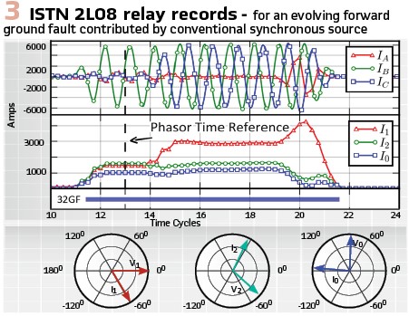
Ground Short Circuit Analysis: On 5th August 2014, 2L08 experienced a Phase B-to-ground fault about 13.5 km from ISTN. After about three-cycles, it evolved into a Phase B-to-C-ground fault. Figure 3 shows 60-Hz bandpass filtered records captured by ISTN 2L08 relay looking into the fault. In this figure: the top analog traces are phase currents; top middle analog traces are magnitudes of the three sequence currents; bottom middle digital trace is status of the negative sequence forward directional (32GF) element in the multifunction microprocessor-based relay; and the bottom phasor diagrams are phase angles of each sequence current relative to its corresponding sequence voltage at about two cycles into fault (see cursor indicating “phasor time reference” on the figure). Zero and negative sequence current contributions were substantial from the strong integrated system. Their phase angles were leading their respective sequence voltages by about 90º as expected in the conventional synchronous system with inductive path to a forward short circuit fault. This phase angle remained consistent even after the fault transitions from Phase B-to-ground to Phase B-to-C-to-ground and did not change until after the fault was cleared. The negative sequence forward directional element asserted shortly after the fault inception and remained asserted until the fault was cleared.
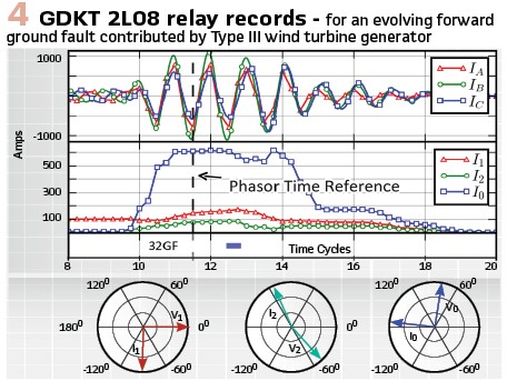
Figure 4 shows records from the GDKT 2L08 relay for the forward fault current by the wind turbine generation. Zero sequence current magnitude was more than 600 A and led the corresponding sequence voltage by about 90° while the negative sequence current was less than 90 A and was almost anti-phase with the corresponding sequence voltage. The negative sequence forward directional element asserted transiently during the event.
Lessons Learned: Short circuit current analysis confirmed that the negative sequence current phase angle relationship with the negative sequence voltage from a Type III wind turbine generator is unlike that of conventional synchronous sources and is not readily known. Therefore, a conventional negative sequence current based scheme can’t provide reliable directional protection against ground faults in situations with high penetrations of IBR influencing short circuit currents. However, if these generators are connected through a transformer that is a source of zero sequence current, then ground fault protection can be achieved using zero sequence current. The protection will be predominantly independent of the type of wind turbine generator or its associated control algorithm because the interconnecting transformer, not the wind turbine generation, is the source of zero sequence current.
Example 2 – Solar Generation Facility: A solar (photovoltaics) generation facility interconnects to the grid through a DC-AC inverter system. Typically, the fault current from the inverter is controlled by the inverter control system within two cycles after the short circuit. In the absence of interconnection and grid requirements, the control system is often programmed to restrict the magnitude of negative sequence current. If an inverter design permits limited supply of negative sequence current, it may have non-inductive source characteristic angle rendering negative sequence directional element unreliable. This section compares line-to-ground short circuits from strong utility source and solar resource to illustrate that negative sequence relaying cannot be applied on a line connecting a solar facility producing negative sequence in insufficient magnitude and/or phase angle.
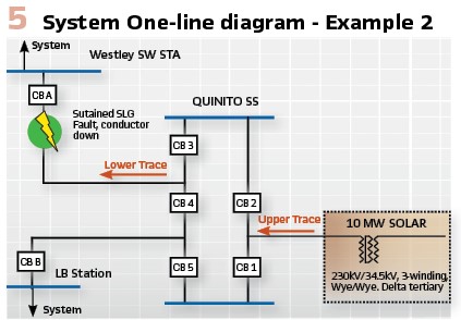
System Description: Figure 5 shows a simplified 230 kV regional one-line diagram of a utility system. In this system, Westley and LB substations are connected to the integrated system having synchronous sources with low short circuit impedance. A 100 MW solar generation facility is connected to Quinito substation through a dedicated 230 kV transmission line. This facility has a three-winding 230/35 kV step up transformer whose configuration is wye-grounded/wye-grounded with delta tertiary serving as source of zero sequence current independent of the inverter control system.
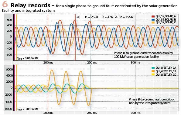
Ground Short Circuit Analysis: A permanent Phase B-to-ground fault was experienced on the transmission line between Westley and Quinito substations. Figure 6 illustrates dissimilar natures of the short circuit currents supplied by the integrated system and the solar generation facility. The upper traces are captured waveforms during the event by the relay located on the 230 kV side of interconnecting transformer of solar facility. Likewise, the lower traces are captured waveforms by the line protection relay located at CB 3 and CB 4 at Quinito substation which was receiving short circuit current contributions dominantly from the conventional sources within the integrated system. The line protection correctly saw an internal transmission line fault whose waveform characteristics were identical to a traditional single phase-to-ground fault. The upper traces illustrate that the solar facility rode through the low voltage caused by a short circuit event external to the line connecting the facility to Quinito. However, the short current characteristic did not resemble traditional single phase-to-ground fault current because of restricted supply of negative sequence current by the solar generation facility. The negative sequence contribution was only approximately 21% of the positive sequence current and 24% of the zero-sequence current, indicating the inverters were limiting their negative sequence current injection in response to the fault.
Lessons Learned: In the absence of an interconnection or grid code requirement, the inverter control system of solar generation facility will likely restrict the magnitude of negative sequence current during unbalanced faults. Consequently, negative sequence relaying cannot be reliably applied on a line connecting a solar facility with this characteristic.
Phase Distance Relays
Many utilities apply mho or Quad characteristics of distance relays for transmission line protection applications. A typical mho relay uses some form of voltage polarization to provide coverage for the faults close to the relay location or near the origin where the self-polarized mho would not produce operating torque. The polarization expands mho relay proportional to the source impedance behind the relay. Dynamic variations in highly inductive source impedance (magnitude and phase angle) behind the relay (in third quadrant) for a forward fault influence this mho expansion that can cause a distance relay to over- or under-reach. A low short circuit current IBR, as shown in Figure 1, appears as a high impedance source behind the relay for a forward fault which in turn significantly expands the mho circle. Since the source impedance depends on the IBR control system, the mho expansion can be anywhere on the R-X plane – not necessarily behind the relay in third quadrant for a forward fault – threatening protection reliability. The non-homogeneous phase angle relationship between an IBR and remote source impedances negatively impacts reliability of a distance relay during unbalanced short circuit involving fault resistances. Most importantly, a distance relay operation is supervised by some minimum phase current. If the IBR output current drops below this minimum value before inherent or intentional added coordination time-delay that the relay takes to operate, the relay will then fail to trip. Depending upon weather conditions, the IBR may not have enough units connected i.e. operating at low capacity prior to developing of fault. Essentially, lack of enough supervising current is a risk to distance relay reliability on the line connecting to IBR.
Backup Undervoltage Protection
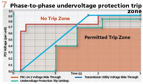
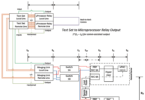
Phase-to-phase undervoltage protection can be provided as backup to safeguard against risk of phase distance relay not picking up at the line terminal where IBR facilities are the short circuit source. This protection is designed to override the slowest clearing faults on the adjacent circuits. In addition, the undervoltage protection should comply with interconnecting utility low voltage ride through requirement and other applicable regulatory standards. Using low voltage ride through of a large Canadian utility and a newly approved North American Electric Reliability Corporation (NERC) standard PRC-024-01, Figure 7 shows no-trip and permitted trip zones (set-points and time delays) used by the utility for back-up undervoltage protection.
Grid Code Remedy
In addition to low-voltage ride through as shown in Figure 7, world utilities are introducing new grid codes requirements to connect the IBR facilities. Figure 8 is an example of dynamic voltage support requirement where IBR is required to supply or absorb positive sequence reactive current to support grid during short term voltage depression or rise. Ability to inject positive sequence reactive current emulates inductive source impedance characteristic of IBR, similar to conventional synchronous generation, during faults and helps reliability of the mho distance relay.
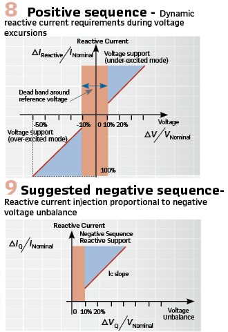
Except for one recently introduced new grid code VDE-AR-N 4130 in Germany, no other utility has a requirement concerning negative sequence current injection. Hence, the IBR manufacturers typically in their present-day control system designs suppress negative sequence current which threatens the line protection reliability i.e. its ability to adequately protect the line during unbalanced faults as illustrated by examples presented earlier. A negative sequence reactive current injection requirement proportional to negative sequence voltage unbalance, as suggested in Figure 9, will aid reliability of protection system operation on short circuit currents from IBR for unbalanced faults.
Also, the IBR control system takes time to measure the voltage depression or unbalance to respond by injecting the positive or negative sequence reactive current and settle down to the required level. This time delay is one or two cycles or up to the maximum delay permitted by the grid code. The IBR transient response during this time can negatively impact the reliability of the high-speed line protection system.
Communication Assisted Line Protection
In spite of the uncertainty of short circuit contributions from the IBR facilities, differential relays provide reliable phase and ground fault protection, as long as one of the line terminals is connected to a strong grid source. This protection operates on the vector sum of total current in the line. The grid source provides high enough fault current for reliable protection even when the short circuit feed from the IBR is limited by its control system.
Permissive overreaching transfer tripping (POTT) scheme reliability can also be ensured with some rudimentary safeguards in the application with IBR at one of the two terminals. POTT schemes use distance relays for high-speed phase fault detection. Use of distance relays at the IBR terminal can pose dependability risk, which can be overcome by echo logic function. Again, as long as the grid source is strong that the distance relay detects internal line fault, it will then operate on echo return even when the distance relay at the weak IBR fails to detect the fault.
All communication assisted line protections require local backup for contingency of tele-protection failure. Time-delayed phase-to-phase undervoltage protection and inverse-time zero sequence overcurrent directionalized by zero sequence polarization protections can be included as local backups.
IBR with Series Compensated Transmission Line Interaction
Different from traditional sub-synchronous resonance (SSR) between a synchronous generator turbine shaft and a series compensated transmission line, the control systems of IBR, particularly Type III wind generation, can interact with a series compensated transmission line to create a new type of sub-synchronous oscillation phenomena, which is often specifically categorized as sub-synchronous control interaction (SSCI).
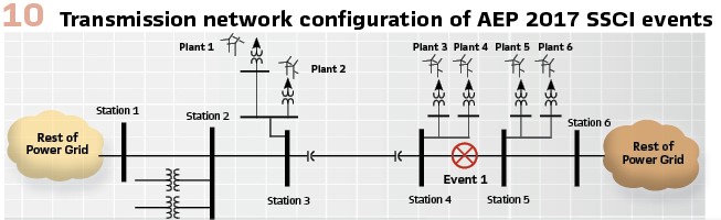
System Description: Figure 10 illustrates the transmission network configuration which experienced two SSCI events on the AEP transmission system in 2017 – one of which is discussed here.
Event Analysis: In event 1, Plants 3 and 4 were radially connected to the rest of the transmission system through the 345 kV series compensated transmission line between Station 3 and Station 4 after the line between Station 4 and Station 5 was tripped.
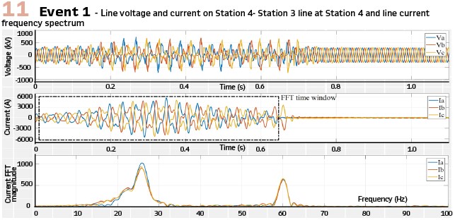
Figure 11 shows the line voltage and current recorded by line relay at Station 4 during the oscillation. Spectral analysis of the line current during oscillation revealed sub-synchronous oscillation frequency of around 25.6 Hz and the magnitude of the sub-synchronous frequency component was almost twice as much as the fundamental frequency (60 Hz) component. The oscillation stopped after Plant 3 and Plant 4 were tripped off the transmission system by the plant protection systems.
Lessons Learned: The undesired impacts of SSCI on power system equipment and system operation included quick rising voltage and current magnitude that could damage system primary equipment including series capacitor banks, synchronous generator turbine shafts, power transformers, etc. Because most relays operate on fundamental frequency quantities, conventional relays may not react fast enough to current and voltages with significant sub-synchronous component and, therefore, to protect power system equipment. Protective relaying, such as transformer protection, may misoperate in the presence of excessive sub-synchronous harmonic components. Although SSCI is a relatively local power system phenomenon, delayed clearing or mitigating of the oscillation could allow the oscillation to propagate through the power system, affect neighboring generation units including inverter based and traditional synchronous power generation units, and create undesired cascading effect to the power system.
To mitigate and/or protect the system from the SSCI issues associated with IBRs, modern SSR relays are now available. Determination of protection settings require extensive analysis which may include a combination of eigenvalue analysis, frequency scans and electromagnetic transient simulations.
Conclusions: IBR responses to balanced and unbalance short circuits can be significantly different than conventional synchronous generators. Traditional protection schemes, which largely rely upon high magnitude and highly inductive nature of the short circuit current from conventional synchronous generator, may not provide reliable protection when operating on controlled current supplied by an IBR. Some countermeasures, as listed below, can be used to overcome risk to the existing protection systems operating in an area with large presence of IBRs:
- Zero sequence ground overcurrent and/or directional protection can be applied as reliable ground fault protection when IBR is connected through a transformer which is a source of zero sequence current
- Reliability risk to memory polarized phase distance and negative sequence relays can be mitigated by enforcing the IBR suppliers to build their systems to supply positive and negative reactive sequence currents during short circuits
- Line current differential is a reliable protection, but it requires high-quality tele-protection channels
- POTT scheme with echo logic can overcome reliability risks posed by IBR facility
- Backup undervoltage protection, located on the line terminal at the IBR facility, can be used
- IBR control system modes can excite sub-synchronous resonances in series compensated lines, particularly when the series capacitor compensated line becomes radially connected to the IBR facility. System planners need to make a careful assessment of this risk and call for custom or special protection
Biography:

Mukesh Nagpal is a Senior Member and distinguished lecturer of IEEE Power and Energy Society, Adjunct Professor at University of British Columbia, Vancouver, (BC), Professional Engineer in the Province of BC and Fellow of Engineers Canada. Currently, he is a Principal Engineer/ Manager with the Protection and Control Planning Department of BC Hydro. He has about 34 years of experience in electric utility research and power system protection. He published about 50 papers, including two IEEE-PES Best Papers. In 2016, Dr. Nagpal received the highest engineering order of BC – R.A. McLachlan Memorial Award – for exceptional leadership in developing practical ways to connect renewables to grid and to improve utility power system in the industry. He received 2016 Outstanding Engineer Award from IEEE-PES Vancouver Section. Dr. Nagpal is also recipient of many BC Hydro’s excellence awards: 2017/18 – Lasting Legacy, 2017, 2013 and 2012 Innovation, 2013 Safety-by-Design and 2007 Mentorship awards.
PSRC WG 13:
Chair – Mukesh Nagpal,
Vice Chair – Mike Jensen,
Secretary – Michael Higginson
PSRWG 13 Members:
Abu Bapary, Jeff Barsch, Michael Bloder, Sukumar Brahma, Duane Buchanan, Ritwik Chowdhury, James Deaton,
Randy Cunico, Alla Deronja, Rui Fan, Evangelos Farantatos, Kamal Garg, Yanfeng Gong, Frank Gotte, Jean-Francois Hache, Ali Hooshyar, Addis Kifle, Hillmon Ladner, Bruce Magruder, Jezze Martinez, David Morrissey, Krish Narendra, Andrew Nguyen, Manish Patel, Nuwan Perera, Joe Perez, Dan Reckerd, John Seuss, Jim van de Ligt, Amin Zamani