by Walter Schossig, Germany, and Thomas Schossig, OMICRON electronics GmbH, Austria
History is the tutor of life
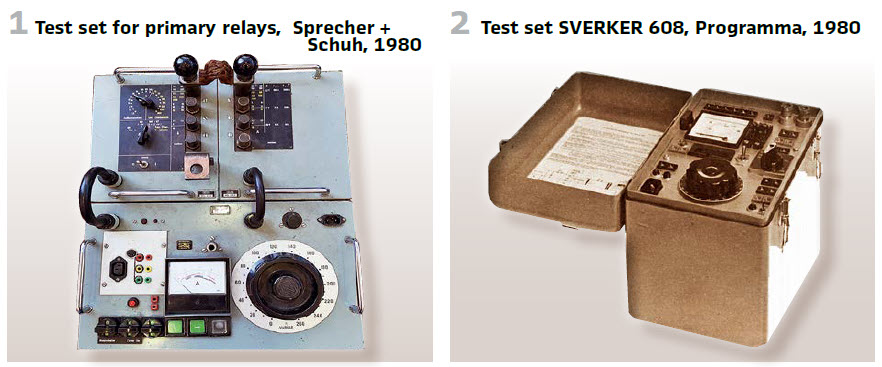
Further developments in protection testing resulted in portable devices, especially for distance protection, directional earth fault relays, generator protection and railways auxiliary functionalities. Some of them have been mounted directly in the cubicles. This was also valid for testing devices. Figure 1 shows such an example of Sprecher + Schuh (Austria, 1980). This device allowed simple and fast check of primary relays types MU, MT and MUT at nominal currents of 300 A with testing values of up to 2000A. The scales allow testing of 3rd party devices as well. The synchronous chronoscope came with microswitches (±6 ms) for exact measurement. To allow easy transport and operation the device was divided into 3 portable units. A dolly could be used for transport.
Programma in Sweden started in 1980 producing the famous SVERKER 608 (Figure 2, table 1) for testing where variable current and voltage are required. Application examples have been current relays, voltage relays, time and power relays. Additional use cases have been measuring of current transformers, ratio tests and plotting of magnetizing curves.
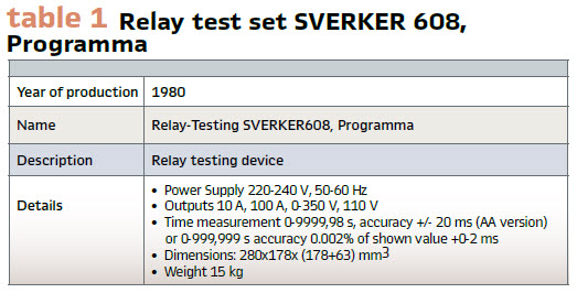
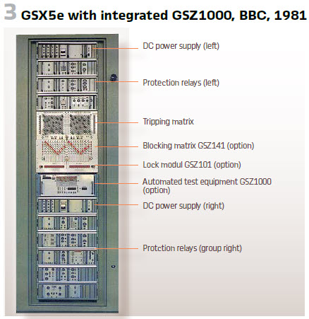
ABB produced the modular static generator protection system GSX5e in 1981. All static relay modules are equipped with test button. This allowed testing the electronics of the relay as well as the functionality of the module. There was one “floor” in the rack used for testing purposes. It was equipped with currents (3A; 15 A). voltages (20V; 110 V and 220 V) and allowed to have 100 V with a phase angle of 90° against the current. The name of the testing floor was GSZ120. This testing system allowed testing (by injecting) of the single protection as well the entire cubicle and its wiring. There was even an opportunity for automated testing. The GSZ1000 is testing the relays in sequences. It is checking startup values and operation times of the relays. They are programmed and compare with the specified value. (Figure 3).
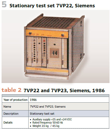
Developing static protection at SIEMENS also resulted in stationary test sets in 1986. The 7VP22 und 7VP23 could be used to test a large amount of centralized protection elements. The special application is the machine protection unit built in the cubicle. The testing includes connections to instrument transformers, protection devices and auxiliary elements, as well as tripping circuits and circuit breaker coils. Possible faults within the machine could be replicated on the secondary side. The testing itself will run automatically. The tripping circuits will be interrupted in this moment for a very short time only – the operating time of the protection. The 7VP22 (Figure 5 and table 2) was used for supervising 9 tripping circuits. The 7VP23 was ready to do so with 18 circuits. It came with a visualization of the operating time.
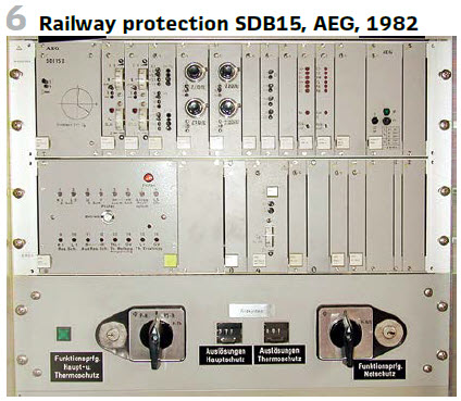
The German Railway is using 15 kV voltage with 16 ⅔ Hz. This requires special protection systems like the SDB15 (AEG). Additionally, they do not just switch off the fault in case of a short circuit- they test if the fault is still existing afterwards over a resistance before switching on again. Additionally, they had built in test devices- AEG presented such a device in 1982 – the SDB15C (Figure 6). With the current delivered, different functionalities such as tripping and indication could be checked. For each feeder a single testing device was built in. This allowed adaptation to the settings of the different feeders. A test transformer 220 V/ 24 V with 16 2/3 Hz with fuse delivered the testing voltage of 24 V. This was available only once, but shared within the cubicle with ring connection. In every test device a switch was built in to allow the test. An interlocking guaranteed that only one feeder was tested at the same time.
Additionally, the railway applies “superior protection” (Ü-Schutz) to protect the entire station. In 1983 AEG presented the SDB401 (Figure 4).
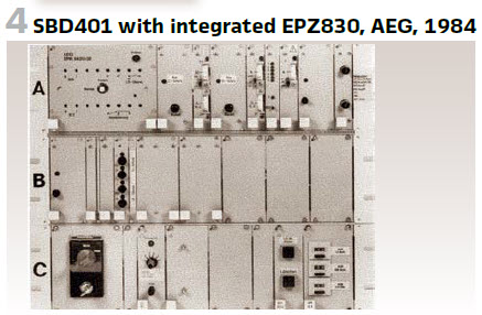
It realizes the backup protection for transformer and line protection. It was also built in the INTERMAS-System (6 units). In another rack (3 HE) the equipment EPZ830 for testing the protection was built in. The weight of the rack with protection was 20 kg, while the test rack was 8 kg.
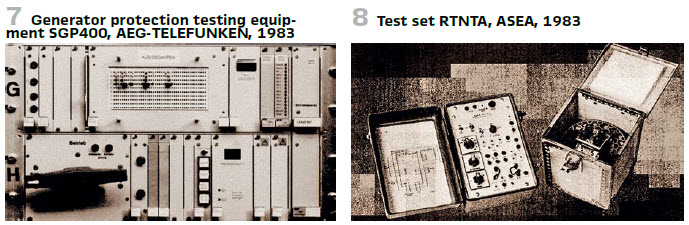
Testing generator protection was the task of AEG-TELEFUNKEN’s SGP400 (Figure 7) in 1983. The 19“ rack consisted of 3 parts. Control elements and testing values generator could be found. Testing was possible during standby, as well as during operation. The SGP400 was built into the cubicle with the protection devices to be tested. A “tripping distribution system” allowed to share the tripping commands via diode plugs (maximum 10 channels). The test must be started manually on site. The maximum amount of different testing cases is 40. To switch to the next sequence could be done manually or automatically. In case of automated testing the test will be interrupted in case of an error. Typical error conditions:
- Missing trip command of the protection device
- Time too long
- Error in testing device
- Startup of the relay because of generator protection
Only the protection function under test is out of service during the test. “Real” faults could interrupt the test and cause a trip.
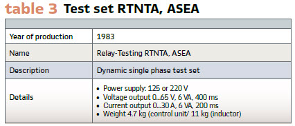
ASEA presented in 1983 the test set RTNTA (Figure 8 and table 3). It was used for dynamic testing of directional wave detectors and could be also used for dynamic, single phase testing of impedance relays.
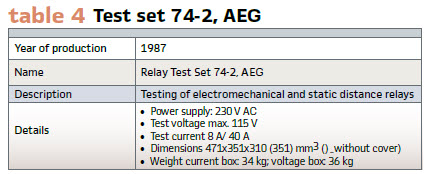
AEG’s RED12 and RED13 have been further developed. In 1984 the test set “74-2” was presented. The application was electromechanical and static protection- focusing on “single relay tests”. With switches multifunctional devices could be tested as well. So, the short circuit angle k of a line could be realized. Angles between 0° and 90° have been possible (step size 1°). A special quadrant regulator extends the range to 360 degrees. The line impedance could be set in the range between 0,01…5,99 Ω; and additional factor between 0.25 and max. 20 could be varied.
So, settings between 0,025 Ω and 119,8 Ω have been possible. The test set consists of 2 suitcases. The first one contains the main elements for setting up the current, choosing the fault, time measurement, mechanical parts and auxiliary devices. The second one could be used for voltage setup, line impedance definition and phase shift between current and voltage. To transport, special cubicles and wheels have been developed. Four power plugs have been added. (see Table 4).
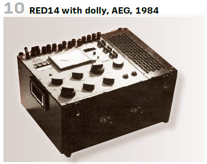
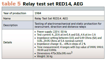
In the same year a further development launched RED14 (Figure 10 and table 5). The main application was again electromechanical and static protection. Overcurrent and distance protection, and directional relays could be tested.
SIEMENS produced also own test sets at this time. The 3-phase set consists of current device (7VP48) and voltage part 7VP49 (see the Figure on page 70 and table 8).
Programma produced FREJA (Figure 12 and Table 7) since 1989. It consists of a computer and the test device for manual and automated testing. 3 phase testing, printer, screen, keyboard- all together. To be moved on wheels, the box can be used as workbench as well.
BBC’s protection series in 1983 was called modures. Its testing part was called XV91-1. It allowed fast and easy function testing which covers functionalities, as well as tripping. The testing could be connected to 4 different feeders and 7 measuring circuits (for instance 2 3-pole and single-phase relays). Rack mounted, it came with golden contacts and a high current connection (Figure 15).
Also, in 1983 the testing device XS91 was produced by BBC. It fits to the accuracy of the modures system, working with single measurement value. The voltage and the current could be controlled. An additional voltage, shifted by 0°, +60°, -120°, -180° allowed the testing of medium voltage relays as well as directional elements. The relays could be plugged to the testing device (Figure 13).
To adapt the distance protection to grid’s characteristics startup characteristics for distance protection have been developed (for instance polygons). Additional swing blocking, saturation detection and others increased the complexity of the protection system. This demanded additional tests at vendors and on site. So, BBC came with the programable test system XS92a in 1985. The built in micro computer (16-Bit) allowed dynamic and static tests and adapting voltages, currents and phase angles in a wide range. The basic setup came on 2 levels, extensions on voltage and current could be mounted on level 3 and 4. Every level could be operated separately and came with its own case. (Table 11). Also, ISA in Italy came in 1985 with their first generation automatic and portable relay test set UTB model (Figure 16 and table 9).
The Soviet company produced in 1985 the test set Y5053. It consists of 3 blocks K513, K514 and K515 (Figure 14, table 6). Block K513 was used for regulating the voltage (AC up to 380 V, DC 240V) and currents (AC up to 10A, DC 4.5A) and measuring the time. Block K514 realized the load and produced single phase up to 200 A. The block K515 is the auxiliary block for simulating faults and errors and for testing the protection with phase sensitive elements. It produced voltages up to 100 V.
The Czech ZPA Trutnov produced the testing device KZ4 also in 1985. The Tester comprises a power supply unit KZ4P and a measuring unit KZ4 (Figure 17, table 10).
SEG in Germany produced an own test set- the PGER in 1987 specifically for secondary testing of directional earth fault relays and for intermediate earth fault detection SER201 & SEW, (Figure 18).
Another example of a one-piece unit of this time is the SR-51 produced by Multi-Amp in Dallas, Texas. It was made for relay testing but could be used for circuit breakers as well. It came with several measurement possibilities.
ZERA developed a computer-controlled relay test system RP86 in 1988 (Figure 19). Depending from the output power the devices could be quite different.
Test sets for conventional protection with more power consisted of main device, voltage amplifier, current amplifier and power supply. The main device came with an external PC.
Also, the German company RUHRTAL presented a portable test set for distance protection and other devices- TZ/3 in 1988.
It came in 2 boxes, which could be operated separately. It was developed in that manner producing a sine wave. Inner ohm-loads and controllable resistances and separate voltages in all phases allowed simulation of all kinds of failures.
walter.schossig@pacw.org – www.walter-schossig.de
thomas.schossig@omicronenergy.com
Biographies
Walter Schossig (VDE) was born in Arnsdorf (now Czech Republic) in 1941. He studied electrical engineering in Zittau (Germany), and joined a utility in the former Eastern Germany. After the German reunion the utility was renamed as TEAG, Thueringer Energie AG in Erfurt. There he received his Masters degree and worked as a protection engineer until his retirement. He was a member of many study groups and associations. He is an active member of the working group “Medium Voltage Relaying” at the German VDE. He is the author of several papers, guidelines and the book “Netzschutztechnik [Power System Protection]”. He works on a chronicle about the history of electricity supply, with emphasis on protection and control.
Thomas Schossig (IEEE) received his masters degree in Electrical Engineering at the Technical University of Ilmenau (Germany) in 1998. He worked as a project engineer for control systems and as a team leader for protective relaying at VA TECH SAT in Germany from 1998 until 2005. In 2006 he joined OMICRON as a product manager for substation communication products. He is author of several papers and a member of standardization WGs.