by Walter Schossig, Germany, and Thomas Schossig, OMICRON electronics GmbH, Austria
Testing made easy (1993)
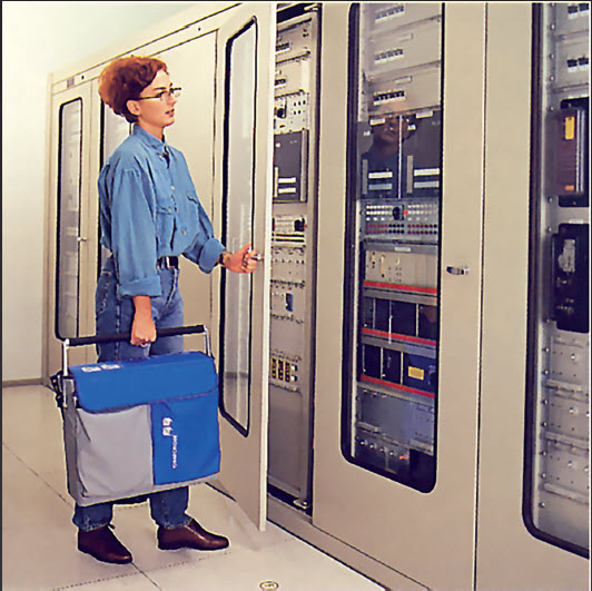
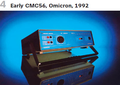
In 1991 OMICRON already introduced a protection test set weighing only 15 kg that can be easily taken to the substation.
History is the tutor of life
In the last issue we moved through the 1980s. The decade after was amazing as well. A lot of portable and integrated testing devices were released. In the 1990s microelectronics became an essential part of the test sets.
In this article we try to cover the most important devices. We are aware of the lack in completeness and kindly request the readers to excuse us for this.
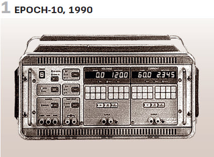
A typical example is AVO’s relay test set EPOCH-10. Launched in the 1990s it was a microprocessor based device (Figure 1 and table 1).
The device could be used for testing of single phase overcurrent, directional, distance and frequency relays. For testing differential relays and open-delta two devices had to be combined and for three-phase distance- and directional relays even three devices.
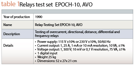
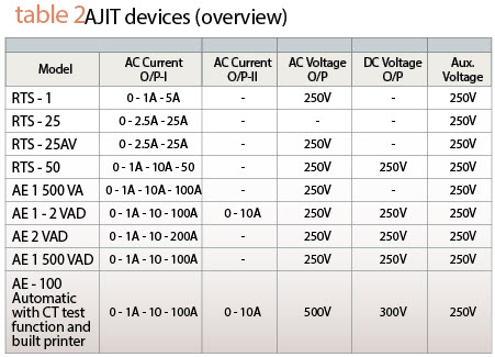
AJIT released several test sets in 1991. They could be used for testing relay startup times and operating times. The series was called RTS and AE (table 2).
Figure 2 shows Relay Test Set AE 100 Automatic with CT test function and built in printer.
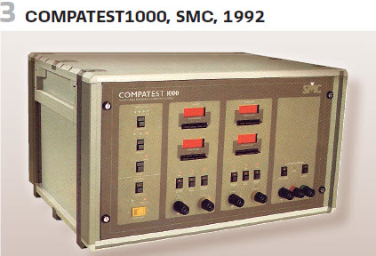
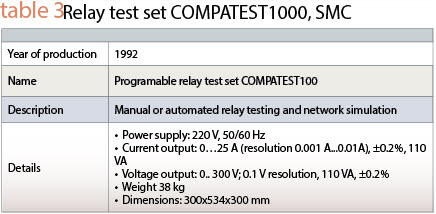
SMC in Spain introduced COMPATEST1000 in 1992. (Table 3). (see Figure 3).
In Germany the utilities started to define requirements specification for “a new test set for protection devices.” The work was done at the “Relais- und Schutztechnik der Vereinigung Deutscher Elektrizitätswerke (VDEW).” In 1992 they published this guideline:
“To test relays specialized devices will be needed. The devices under test might be electromechanical, static or digital. They can be overcurrent relays up to multisystem distance relays. Test sets, which will fulfill all requirements will not be accepted in the industry if they have huge dimensions. That is why the requirements must be justified, and some wishes might not be included. For lab use the requirements might be different. Electromechanical relays might need additional devices. The test set must be handy and robust. The weight should be less than 20 kg (with suite case). This is also valid for auxiliary devices such as amplifiers. The temperature range shall be between -25°C and 70°C for transport.” Table 4 summarizes the most important requirements:
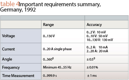
Every of the values to be defined (voltage, current, impedance, …) shall be set up easily and fast via mouse or keyboard. Static and dynamic tests have been required. An automatic testing without intermediate operation was required, together with the ability for individual test programs to be defined and saved.
Here is a story that the author of this article W. Schossig wants to tell about a personal experience from his professional life in the early 1990s.
In the 1990s microelectronics became an essential part of the test sets.
“In 1992 I said to my colleagues: Guys, there will be a visit of some communication guys from Austria. They want to show us how to test protection. Let’s have a look. The two guys were Rainer Aberer (he died in 2009) and Reinhard Kuntner (retired in 2019). Rainer was the founder of OMICRON in 1984. We gave them a REL316 relay which was parametrized.
They used a CMC56 to demonstrate entering the values, testing the relay with startup values and characteristics, saving the values on a floppy disk and printing it out. Our dreams became a reality. This was what we have been looking for.
Rainer Aberer (see interview in the Summer 2009 edition of the magazine) and his team of 10 developers for hardware and software presented the CMC prototype in 1990. The predecessor was developed for calibration of measuring transducers.
Since they were not as familiar with the terms in the English language at the time they called it “calibration of measuring converters” – the CMC was born. They were good in engineering and communication technology at that time- but not at all in protection. This changed dramatically and the revolutionary new test device was the basis for international success of OMICRON’s CMC.
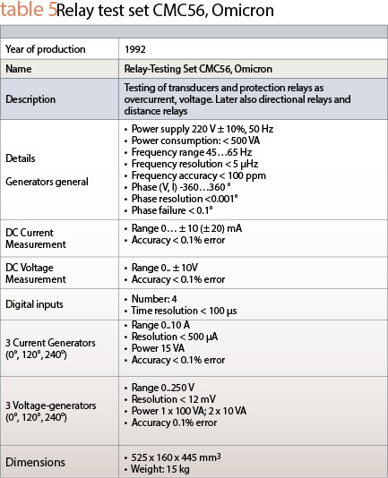
The first series could be produced in March 1991. In 1993 a hundred devices had been ordered already. Figure 5 and table 5 show the CMC56.
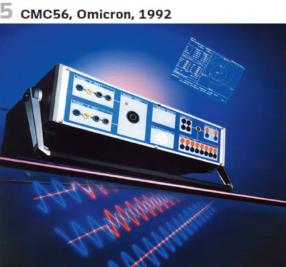
It was not just the device. The MS DOS software came with revolutionary vector view. The development of distance protection testing software started also in 1991. Further modules such as :
- f, V, I – relays
- Transducers 1 phase/ 3 phase
- …
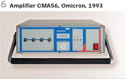
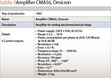
were very innovative and defined a new approach for relay testing. If more current was needed, the amplifier was developed. The CMA56 is shown in figure 6 and table 6.
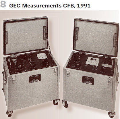
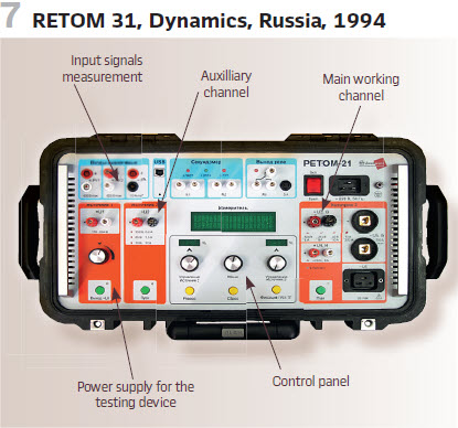
Looking back to the English-speaking countries, GEC was widely used. GEC Measurements produced relays and test sets. Examples from the late 1980s and early 1990s are Type CFB Portable test equipment for overcurrent relays and Type ZFB for distance relays (see June 2019 issue).
The type CFB test equipment has been designed primarily for testing of inverse time overcurrent relays, at 50 Hz, particularly on site where portability and a steady current output are essential requirements.
The current in the CFB was controlled by series reactance. In order to suppress the harmonics, tapped non-saturating air gap reactors have been utilized. In this way, because the resistance component is relatively small, a good waveform can be obtained with minimum power dissipation.
This in turn means that the whole equipment could be made much smaller and lighter for ease of transport. The test equipment contained a primary supply circuit to which the relay is connected by a current injection transformer.
The primary circuit current is available from 1A – 40 A and is adjusted by means of rough, medium and fine controls (Figure 8). (see Table 7).
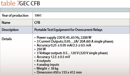
From the UK we are moving to Russia.The scientific-production enterprise «Dynamics» (SPE «Dynamics») was founded in 1990 by a group of specialists from All-Union Research Relay Construction Institute, Cheboksary. The Company’s management is former designers of many Soviet relay protection devices for 6-1150 kV power utilities.
In the years 1990 – 1992 first researches and developments were accomplished for RAO UES, ODU Center, research Institutes in Kiev and Warsaw, as well as for SIEMENS. In 1994 they launched the new generation computer-based testing system RETOM-31 (Figure 7) designed for relay protection equipment testing which has become popular in the Russian market.
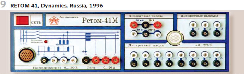
Later in 1996 RETOM-41(M) (Figure 9) based testing system RELAY-TOMOGRAPH-41 came out and is well known to all relay specialists in Russia and CIS countries. Development of special RETOM-41 programs for automatic testing of the most frequently applied relay protection and automation devices was also started.
It consisted of the test set and a computer. Additional amplifiers (RET-10) have been available as well.
Some of the most important technical data are summarized in Table 8.
AVO was mentioned already. In 1993 AVO Multi-Amp Corporation introduced PULSAR®Universal Test System (Figure 10).
The complete three-phase test system in one unit came with a modular design for system customization. It allowed steady-state and dynamic testing, transient testing via fault records replay and EMTP/ATP simulation. It was capable of GPS satellite synchronized testing. It became a Megger company.
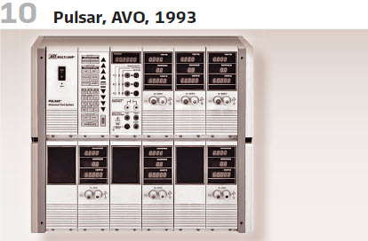
The PULSAR base unit includes the chassis, back plane, and input power and control module.
The system was customized by adding a timer module and the number of current and voltage amplifier modules needed for specific testing applications. For example, adding the timer, one current amplifier module and one voltage amplifier module to the base unit provides a variable ac/dc current and voltage output, adjustable phase angle and frequency settings, and comprehensive
control, timing and monitoring circuits. This configuration tests single phase relays. Add up to three current and three voltage amplifier modules to create a full, three phase relay test system in one portable unit.
For high-current applications, PULSAR could be connected to the Multi-Amp EPOCH-20‚ and
EPOCH-II‚ High-Current Output Units. The Multi-Amp High-Current Interface Module provides the control interface between PULSAR and the EPOCH-20 or EPOCH-II to provide high-current, high volt/ampere output for single-, three- or six-phase testing.
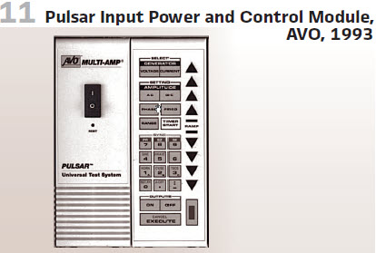
The Input Power and Control Module (Figure 11 came with RS-232 interface port, optional IEEE-488 GPIB and manual control keypad.
The Timer, Monitor and Battery Simulator Module was designed to slide into one slot of the PULSAR unit. The timer was specifically designed to measure high-speed operation of electromechanical, solid-state and microprocessor-based protective relays. It incorporated three sets of banana-plug receptacles.
Due to the flexibility of the system we will not include a table with the technical details.
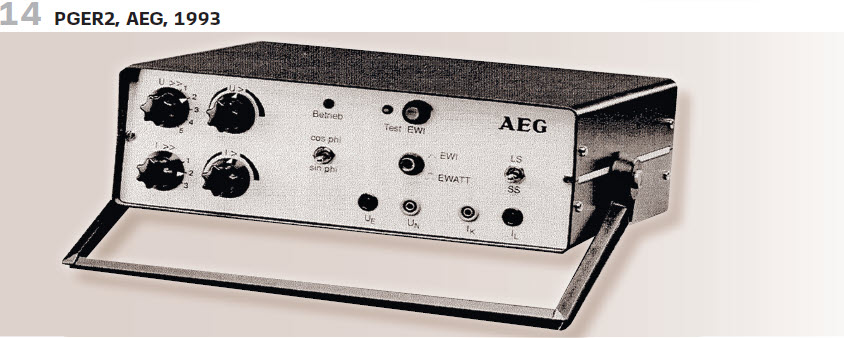
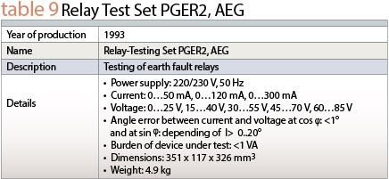
At the end of this article we are moving back to Germany and AEG. As a further development of the earth fault directional relay test set PGER (1987) the PGER2 was released in 1993. (see Figure 14 and Table 9).
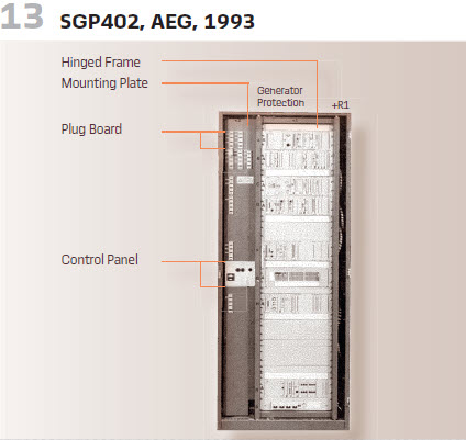
1993 was also the year where the generator protection testing device SGP402 was released by AEG (Figure 13). It was manually controlled.
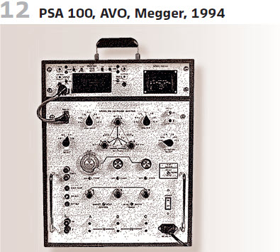
Manual control was also used for AVO’s PSA-100(1994, Figure 12).
Biographies
Walter Schossig (VDE) was born in Arnsdorf (now Czech Republic) in 1941. He studied electrical engineering in Zittau (Germany), and joined a utility in the former Eastern Germany. After the German reunion the utility was renamed as TEAG, Thueringer Energie AG in Erfurt. There he received his Masters degree and worked as a protection engineer until his retirement. He was a member of many study groups and associations. He is an active member of the working group “Medium Voltage Relaying” at the German VDE. He is the author of several papers, guidelines and the book “Netzschutztechnik [Power System Protection]”. He works on a chronicle about the history of electricity supply, with emphasis on protection and control.
Thomas Schossig (IEEE) received his masters degree in Electrical Engineering at the Technical University of Ilmenau (Germany) in 1998. He worked as a project engineer for control systems and as a team leader for protective relaying at VA TECH SAT in Germany from 1998 until 2005. In 2006 he joined OMICRON as a product manager for substation communication products. He is author of several papers and a member of standardization WGs.