by Alex Apostolov and S.S. (Mani) Venkata, USA
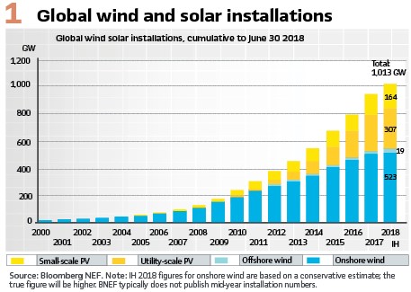
Since the beginning of the 21st century the development and installation of renewable generation globally exploded exponentially becoming a source of large amounts of clean power. The COVID-19 pandemic did not slow this development. It is estimated that in 2020 the global increase of renewable generation was 45% compared to the year before.
The size of the virtual power plants is growing as well. There are already multiple solar lants of more than 500 megawatts in California, and in India and China there are already solar power plants producing more than 2 gigawatts of power under optimal conditions.
However, due to the nature of the energy sources – typically wind and solar, the virtual power plants based on this technology are located in remote areas far from the large load centers. It is clear that this creates a problem – how to deliver the power from where it is produced to where it is needed. There are already times when grid operators have to dump energy produced by wind turbines on windy days because regional power systems cannot handle it.
The obvious solution is to build new transmission lines, but this is not that simple. Building a new transmission line is quite expensive, usually faces a lot of opposition from environmentalists and also a prolonged process of getting permissions, securing right of ways and all the other bureaucratic hurdles. And on top of everything it is very expensive and time-consuming.
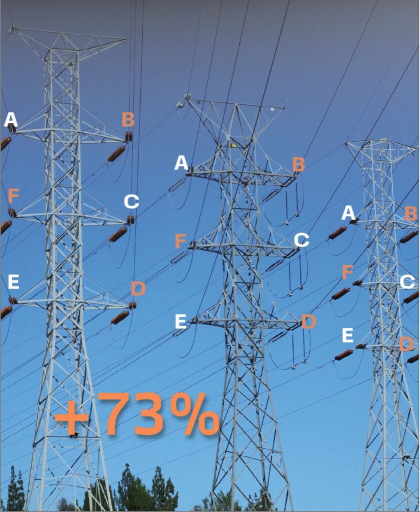
That is why many utilities around the world have been looking at all the possible solutions to the problem. But there is one potential solution that almost nobody is talking about – six-phase transmission. What will happen if we tell the industry that we can increase the power transfer of many of the existing double circuit transmission lines by 73%, this may meet many of the existing requirements for transferring power from the new renewable power plants to the large load centers that these transmission lines are already connected to. This appears to be the most promising solution, because it meets the need to increase the capability of existing transmission lines and at the same time respond to the concerns over electromagnetic fields.
Six-phase Transmission
The interest in six-phase transmission was triggered by a CIGRE report on High Phase Order Power Transmission (Report presented by Study Committee No. 31 Transmission Systems) by L. Barthold and H. Barnes, 1972. This resulted in it being considered as an alternative in system planning by some utilities in the United States.
Allegheny Power System (APS) at the time had several hundred miles of 138 kV three-phase double-circuit lines and was looking at increasing the power transfer capability of these transmission line corridors without major rebuilding. One alternative considered was to upgrade the towers to 230-kV operation.
The number of insulators, conductor sizes, and tower spacings of the existing 138 kV three-phase double-circuit lines suggested that an upgrading of these lines to 230 kV double-circuit may be possible. The second option was to consider conversion to 138 kV six-phase lines.
Since the initial publication of the CIGRE report in 1972, the concept of six-phase has been described in the literature in several papers and reports, some of which were products of a joint Allegheny Power System (APS)-West Virginia University (WVU) study of the feasibility of 138 kV six-phase conversion as an alternative to 230 kV three-phase double-circuit conversion undertaken during 1976-79.
This work explored the potential for increased power transmission capability of existing rights-of-way with existing conductor thermal limits by 73%. It was considered that the 138 kV six-phase line may have the following advantages over a 230 kV double-circuit line: reduced conductor gradients, potentially better public acceptance since nominally it will remain a 138 kV system, stability characteristics and potentially lower electromagnetic fields, audible noise levels, radio interference levels, etc. A significant part of their research was dedicated to the analysis of the different possible fault combinations on the six-phase transmission line and the methods for their calculation. This established the foundation for an EPRI research project in 1984 on fault protection for High Phase Order transmission lines.
A feasibility analysis of High Phase Order transmission was also conducted in the 1970s by the US Department of Energy and based on the encouraging results let to the construction of six and 12 phase test lines at an experimental site at Malta, New York State.
The six-phase line was energized and tested at 80 kV. The results from the testing and analysis verified the conclusions of the theoretical analysis and resulted in a decision for a demonstration projects to show the commercial viability of the technology.
NYSEG’s Six-phase Demonstration project
It took about two decades of research for the industry to make a decision to try the concept of six-phase transmission in real life conditions. A High Phase Order Transmission Demonstration Project sponsored by the Electric Power Research Institute (EPRI), the Department of Energy (DOE), Empire State Electric Energy Research Corporation (ESEERCO), New York State Energy Office (SEO), New York State Energy Research and Development Authority (NYSERDA) and New York State Electric & Gas Corp. (NYSEG) was initiate to convert an existing 115 kV double circuit line to a six-phase line to demonstrate the commercial viability of the concept.
The project had several main objectives:
- To prove that it is possible to operate a six-phase transmission line integrated into an existing three phase network
- To design and implement the interface of the six-phase line to the three-phase system in the most efficient way
- To design and identify all potential issues with the protection and control of the six-phase transmission line
- To confirm the expected environmental benefits of transforming a double circuit three phase line into a six-phase single circuit
- To demonstrate that the existing double circuit three phase towers can be used for the six-phase transmission
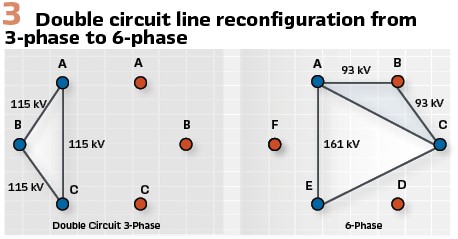
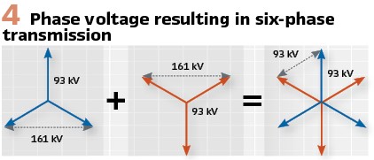
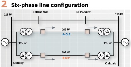
After detailed analysis of many double circuits transmission lines in NYSEG’s system it was decided to select the 1.5 miles (2.4 km) long 115 kV transmission line from Goudey Station to Oakdale Substation for the demonstration. The analysis of the tower configurations concluded with a decision to operate the line as a 93 kV (phase to phase and phase to ground) six-phase line. (see Figure 2, 3 and 4). The conversion is achieved using two sets of 161/115 kV 48/64/80/ MVA transformers (with a common ground) at Goudey and Oakdale. One of the transformers at each end was connected delta / grounded wye and the other was connected delta / inverted grounded wye. These transformers were referred to as the conversion transformers.
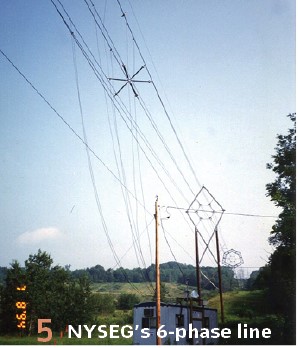
Breakers with single pole control capability were located on the six-phase line side of the transformers in order to support single phase trip and reclose, as well as operation of the circuit with one or more phases out of service. (Figure 5).
Protection System
The complexity of the protection of a six-phase line compared to the protection of a conventional three-phase system results from the increase in the number of possible fault combinations. Considering short circuit faults with all six phases in service and no open circuit faults, the number of fault combinations for the six-phase line is 120.
This number increases significantly if we consider fault combinations when the six-phase line is operated with reduced number of phases (i.e. with five, four or three phases in service).
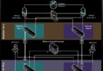
The design of the protection system was based on the use of off-the-shelf state of the art three-phase multi-functional microprocessor-based relays at each end of the six-phase line. Multiple IEDs with main protection functions of different types were integrated together into a six-phase protection system by a common six-phase microprocessor-based logic device (Figure 6).
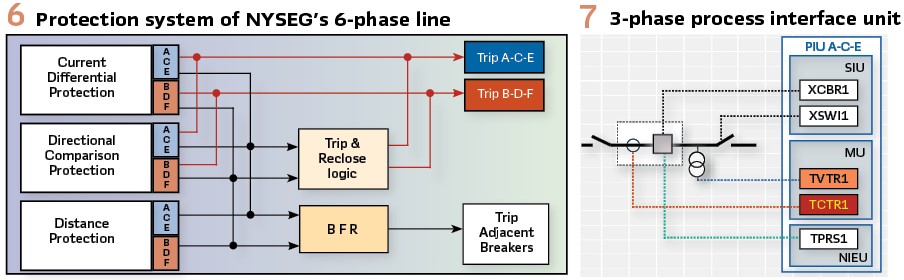
Since we were using three-phase protection devices, the six phases of the line were divided in two three-phase groups, one of them (a-c-e) connected to the wye/delta transformer, and the other (b-d-f) connected to the inverted wye/delta transformer. Each three-phase group is protected by relays designed for conventional three-phase transmission lines.
The primary protection for the 93 kV six-phase line consisted of two three-phase current differential relays. The relays communicated with the remote-end through a dedicated fiber optic link and compared the local current to the remote current on a per phase basis.
A second primary protection is provided by a directional comparison relay. It is a high-speed protection device operating based on the superimposed components directional detection principle. The direction of the fault is determined using the fault-generated changes in the voltage and current signals at the relay location. The relay communicates with the remote end device via dedicated fiber optic communication channel. In case of channel failure, the relay has a built-in delayed distance, channel independent element.
A three-phase microprocessor-based distance relay was used as a back-up, communications independent protection with separate measuring elements for each zone and fault type. The relay also had a directional ground overcurrent function.
Relay communications between the two substations was provided by two fourteen fiber, multimode fiber optic cables helically wrapped on the two bottom phases of the six-phase line.
Breaker failure protection was also provided with three single-phase measuring elements packaged together with independent output element for each phase. The protection system was designed to provide correct operation for any of the hundreds possible faults.
All three-phase independent relays were integrated into a complete six-phase protection system by a trip and reclose logic device. This device was a microprocessor relay operating based on a logic defined in the form of a ladder diagram.
The Trip and Reclose Logic obtained information about the status of all the independent protection relays and each pole of the circuit breaker by means of relay and breaker auxiliary contacts.
The basic principles used in developing the logic were:
- Recognize the phase selection of the primary relays (current differential and directional comparison)
- Trip and reclose based on the determined (based on the operation of the primary relays) six-phase fault type
- The two primary relays directly trip individual breaker poles and provide phase selection information to the logic relay for reclose and lockout functions
- Because of concerns about the proper phase selection of the distance relay, it is not allowed to trip directly except in the event that both primary communication systems are inoperative or it is a time-delayed trip.
- Only single-phase, high speed autoreclosing was used for faults involving one phase from each three-phase (a-c-e) or (b-d-f) group under normal operating conditions (all six-phases in service). For other faults a three-phase or six-phase trip and block of autoreclosing was applied
- Time-delayed trips initiate three-phase trip in the faulted group
- Unsuccessful autoreclosing initiated single-phase trip and lock-out.
- Evolving faults during single-phase open interval-initiated trip of one or both three-phase groups and lock-out
The overall six-phase protection system may be considered as a hierarchical system with two control levels. The lower level is the different relays designed for conventional three-phase transmission lines. These relays identify the faulted phases in their three-phase group and send single or three-phase trip signals to the breakers and the upper level – trip and autoreclose relay (Figure 6).
The trip and autoreclose relay identify the faulted phases from a six-phase perspective based on information from both three phase groups and is responsible for the overall operation of the system. The relay monitors certain system operating conditions and adds intelligence to the overall protection system. For example, when the system is operating with one phase open, a fault occurring on the opposite phase will be seen only as a single pole trip condition by the primary relay, but it will be converted to a six-phase trip by the trip and reclosing relay, utilizing an upper level hierarchical system.
Six Phase Line Model for Three-Phase Short Circuit Study
The High Phase Order transmission line between Goudey and Oakdale was represented in the conventional sequence impedance model of NY State Electric & Gas’s three-phase system with its corresponding positive and zero sequence impedances. The High Phase Order line model included two sets of 161/115 kV 48/64/80/ MVA transformers at Goudey and Oakdale – one of them with grounded wye/delta connection and the other with inverted wye (grounded) /delta connection and two three-phase 161 kV mutually coupled transmission lines was based on the correct representation of the actual line reconfiguration (Figure 3).
Both the grounded wye/delta connected transformers and the inverted wye (grounded)/delta connected transformers were modeled as three-phase power transformers.
The six-phase line itself was modeled as two three-phase (a-c-e and b-d-f) 161 kV mutually coupled transmission lines with a double circuit configuration (one static wire).
The positive and zero sequence impedance of each of the three-phase lines, as well as the zero-sequence mutual impedance between them was calculated based on the shifted phase configuration using a Line Constants program.
February 1993 Fault on NYSEG’s 6-Phase Transmission Line
The six-phase line was energized in July 1992 and was operated as a six-phase line for three years. During that time different aspects of the high phase order transmission concept such as operation with one, two or three phases out of service and the application of existing relay systems designed for the protection of conventional three-phase transmission lines were demonstrated.
During that time the protection system operated successfully for two faults in 1993. The second fault occurred at 7:15 a.m. on February 19, 1993, during an extreme cold spell (-32 F/-36 C) a section of the static wire on the six-phase line from Goudey to Oakdale broke. On its way down it caused a single-phase (phase d) to-ground fault. All the relays operated correctly as follows:
Both ends tripped phase d, reclosed high-speed single-phase (phase d – unsuccessful), tripped phase d again and locked-out with the remaining five healthy phases in service.
The current differential protection, directional comparison protection and distance protection selected properly phase d (BN) as the faulted phase.
After about 15 minutes operation with five phases the line was deenergized by remote operators.
The six-phase logic relay operated according to the protection design: high speed single-phase trip and single shot single-phase reclose with five phase post fault lock-out.
The results from this fault also once again proved the accuracy of the six-phase line model in the short circuit study. The fault was modeled as a single-phase to ground fault at 57 % of the line from Goudey with 2 ohms fault resistance. The calculated zero sequence currents compared to the fault currents measured by the relays were as shown in Table 1.
All the testing during the commissioning of the six-phase line and the two actual faults demonstrated that even with technology available more than 30 years ago it was possible to design and implement successfully a selective and reliable protection system and also use off-the-shelf IEDs, short circuit and protection coordination software designed for conventional three-phase systems.
Protection of Future 6-phase Lines
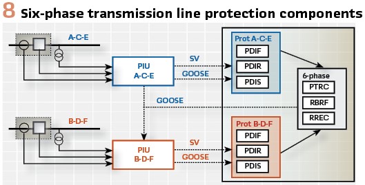
Considering that the protection, automation and control systems (PACS) of future 6-phase transmission lines will be implemented in digital substations, it is clear that they will be distributed hierarchical systems using IEC 61850 object models and communications. This is because the processing of the analog and binary signals from the substation equipment in the yard is performed by different devices that are connected to the 6-phase PACS using fiber optic cables. These devices we can call process interface unit (PIU). The process interface devices can be with different levels of complexity depending on which process interface functions they are implementing.
For the envisioned PACS we use the following naming conventions:
- Merging Unit (MU) converts analog signals (currents and voltages) into time-synchronized streams of sampled values according to IEC 61850-9-2 of IEC 61869-9
- Switchgear Interface Unit (SIU) provides a binary status and control interface for circuit breakers and switches
- Non-Electric Interface Unit (NEIU) converts analog signals from non-electric sensors into time-synchronized streams of sampled values according to IEC 61850 9-2 or GOOSE messages according to IEC 61850-8-1
- Process Interface Unit (PIU) combines two or more of the functions listed above
The different process interface units communicate with the substation 6-phase PACS using the required IEC 61850 services. The communications architecture depends on the specifics of the substation and the requirements for performance, reliability and security. Redundancy protocols such as PRP are used to improve the reliability of the system. All components of the PACS are time-synchronized based on IEC 61850-9-3 (a PTP profile).
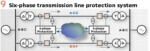
Two PIUs – one for A-C-E and the second for B-D-F will be used (Figure 8). Typically, they will be duplicated for redundancy.
The 6-phase PAC device will subscribe to the sampled values and GOOSE messages from the A-C-E and B-D-F PIUs and will use them to perform the required PAC functions.
Based on the experience from the NYSEG’s demonstration project it is clear that they implemented principles can be reused for future systems using the available new technology.
As shown in Figure 8 the main protection functions for each three-phase group will be:
- Superimposed components based directional comparison protection (PDIR)
- Line differential protection (PDIF)
Both of these functions will operate based on the streaming sample values, which will result in much faster operating times – in the range of a few milliseconds. Both main protection functions will require communications with the similar devices at the remote end of the six-phase line. In case of complete failure of all communication channels a backup distance protection function (PDIS) will be used.
The outputs from the two A-C-E and B-D-F protection logical devices become inputs into the six-phase trip and reclose logic function. Based on a logic similar to the one described for the NYSEG’s project a decision will be made to implement single or multiphase trip through PTRC, as well as initiate breaker failure protection RBRF and autoreclosing RREC. Once the trip decision is made, a GOOSE message is published that is received by the A-C-E and B-D-F PIUs to operate the single pole breakers as required, depending on the specific type of fault.
The overall 6-phase line PACS can be implemented using different communications technologies. For the sampled values-based line differential protection it is expected that fiber optic communications will be used, at least in the near future. For the directional comparison protection GOOSE over fiber, as well wide-area GOOSE are applicable. (Figure 9).
Let’s do it: Based on everything described in this article it is clear that there is an urgent need for increasing the transfer capability of existing transmission lines and that a viable alternative to achieve this goal is to convert existing double circuits three phase lines into six-phase lines that can transport more than 70% additional power.
The fact that existing three phase PAC IEDs, short circuit analysis and protection coordination programs can be used in the projects makes it really possible to implement them without significant changes in the way we do things. So, let’s look at it and do it to help the industry in these challenging times.
Biographies:

Dr. Alexander Apostolovreceived his MS degree in Electrical Engineering, MS in Applied Mathematics and Ph.D. from the Technical University in Sofia, Bulgaria. He is Principal Engineer for OMICRON electronics in Los Angeles, CA. He is an IEEE Fellow and Member of the PSRC and PSCC. He is past Chairman of the Relay Communications Subcommittee, serves on many IEEE PES WGs. He is a member of IEC TC57 WGs 10, 17, 18, 19, Convenor of CIGRE WG B5.69 and member of several other CIGRE B5 WGs. He is a Distinguished Member of CIGRE. He holds 4 patents and has authored and presented more than 500 technical papers. He is an IEEE Distinguished Lecturer and Adjunct Professor at the Department of Electrical Engineering, Cape Peninsula University of Technology, Cape Town, S. Africa. He is Editor-in-Chief of PAC World Magazine.

Subrahmanyam Venkata is President of Venkata Consulting Solutions Inc. He was with GE Power/Alstom Grid Inc. from January 2011 to September 2017. He continues his affiliation with the University of Washington (UW), Seattle, Washington where he has taught since 1979. Dr. Venkata is a Life Fellow of the IEEE. At the IEEE level, he served as a member of the IEEE Fellows Committee for five years. He also served on the PES Board as Vice-President, Publications PES during 2004-07. In 2016 he received the Robert M. Janowiak Outstanding Leadership and Service Award from ECEDHA. In 2015 he received the IEEE PES Douglas M. Staszesky Distribution Automation Award. In 1996 he received the Outstanding Power Engineering Educator Award from the IEEE Power Engineering Society.