by Colleen Konsavage, and Sebastien Billaut, Commonwealth Associates, Inc, USA

As microgrid deployments increase worldwide, the penetration of inverter-based resources (IBRs) also continues to rise. Due in part to IEEE 1547, an IEEE standard providing the criteria and requirements for the interconnection of microgrids to utility scale grids, ride-through requirements demand microgrid designs demonstrate exceptional resiliency in transient and fault conditions.
This article presents the importance of fault protection in IBR microgrids, their unique controlled response characteristics, how these responses challenge current state-of-the-art distribution protection systems, and a patent-pending solution for cost-effective, scalable fault isolation solution in microgrids with high penetration of IBRs.
Why are Microgrids relevant?
Microgrids are power systems with the ability to both operate as part of a larger, traditional power grid, or disconnect and operate as an autonomous subunit. Microgrids are especially useful in allowing local-based generation to serve critical loads during outages from the primary grid, as in the case of natural disasters or cases where load is isolated from large-scale generation. This reduces the impact of grid disturbances on customers and aids in overall system recovery during major transients. In this way, microgrids increase reliability and resiliency of the nation’s overall power delivery. Additionally, microgrids may serve as a proving ground for technologies that may later scale up to widespread implementation across the widespread bulk electric system.
According to the US Energy Information Administration’s website “Electricity Explained: Electricity Generation, Capacity, and Sales in the United States,” there were 1.2 million MW of generation in the US in 2020, 13% of which was from nonhydroelectric renewables. According to the Office of Energy Efficiency and Renewable Energy’s website “Department of Energy Releases New Tool Tracking Microgrid Installations in the United States,” of all US generation, only 3,100 MW (0.25%) was via microgrids. However, in the coming years, microgrid deployment, and IBR microgrids in particular, is expected to increase.
The DOE Solar Energy Technologies office projects that more than 1 in 7 U.S. homes will have rooftop solar photovoltaic (PV) systems by 2030” via “Solar Energy in the United States.” At least 16 U.S. states have set ambitious 2050 targets to reduce carbon emissions – some as much as by 90% in the case of Washington and Colorado, compared to 1990 and 2005 levels respectively. In addition, 30 U.S. states have set clean electricity standards requiring a certain percentage of electricity sold by utilities to be renewably sourced, per Laura Shields’s article, “Greenhouse Gas Emissions Reduction Targets and Market-Based Policies” at the National Conference of State Legislatures. Although traditional generation sources may remain in some parts of the country, utilities could anticipate pockets in the traditional grid that are 80-100% renewably sourced.

Methods to adequately protect the utility system from electric faults are an important part of the viability of power grid evolution. Without fault isolation, the ultimate consequence of a fault would be a complete Microgrid outage. As the nation pivots to increasing reliance on inverter technologies through renewable generation sources or battery energy storage sources, utilities cannot rely on the same large generation, long distance transmission protection technologies to address this new composition of power generation and delivery.
The Problem: Manufacturer Specific Inverters Define Fault Current Characteristics in Islanded Inverter-Based Microgrid: One substantial design challenge for the successful implementation of inverter-based (i.e. solar, battery, wind), gird-forming AC power systems is the ability to reliably detect and clear system faults to ensure safe and reliable power flow. These faults are particularly challenging to accurately locate in IBR microgrids in islanded mode because the low fault current and often unstable negative sequence current provided by these non-reactive, inverter systems invalidate the usefulness of existing fault isolation technology. In these situations, abnormal, reduced voltage on faulted phases may allow for conventional protection systems to identify that a fault has occurred, but do not consistently allow for reliable, timely identification of the specific fault location, and subsequent isolation of the fault in an easily scalable, cost-effective manner.
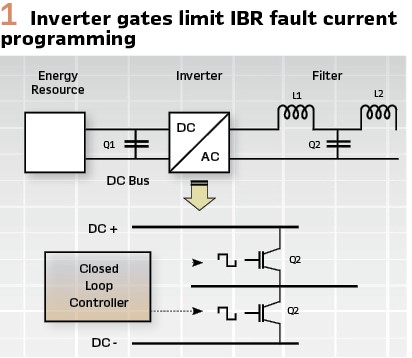
There are no scalable, low-cost commercial products to reliably detect and isolate faults in islanded IBR microgrids. When existing AC distribution systems are used as a microgrid in islanded mode, the standard practice relies on contributions from synchronous-based generation sources (4-10 times greater than continuous rated current) to achieve sufficiently high fault current for tripping and isolation. In the absence of synchronous sources, as would be the case in a fully PV & battery-based system, modern overcurrent fuses, and reclosers would not reliably trip for faults in the system. This is because inverter generation sources often do not see inertia to carry fault current based on electromagnetic characteristics, resulting in a quickly decaying time envelope due to the lack of inductive characteristics (Figure 1). Studies by the National Renewable Energy Laboratory have demonstrated low penetration of IBR DERs to contribute ~1-2 times rated continuous current for <1 cycle; high penetration contributes ~2-4 times rated continuous current for 0.06-0.25 cycles.
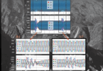
In theory, inverters could be programmed and fabricated with response times or fault output comparable to inverter-based sources; however, in practice inverter response characteristics vary by manufacturer and are designed to optimize cost, reducing the withstand capabilities of the inverter gates and therefore reducing the overall overcurrent capabilities and functions of the inverter. Functionally, this results in inverters generally limiting the amount of fault current produced. As an example, consider a power system simulation with inverter-based resources and a line-to-ground persistent (“bolted”) fault as shown in Figure 2, modeled in PSCAD power system software. After a fault is initiated, the simulation shows an initial current peaking at 2.5pu or less within 0.15 cycles, then resolving to 1.1-1.2 times load current as a steady-state bolted fault.
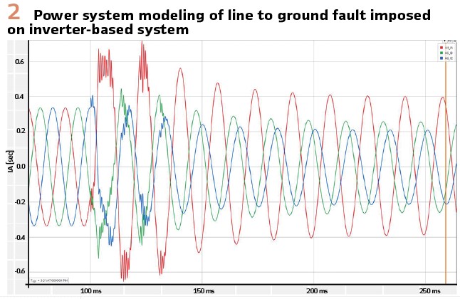
The essence is that both current magnitude and phasing remain relatively constant before and after a line-to-ground fault happen on an inverter-based system. Overcurrent protection methods applied to systems like these, which see fault current values hovering so closely to typical load current values or quickly decaying, may result in an anticipated tripping time of minutes or hours for traditional reclosers, breakers, or fuses. In some cases where traditional overcurrent settings philosophies of set value and timing are applied, the system may not trip at all. Consequently, methods other than overcurrent protection must be explored for devices to reliably and quickly isolate faults for IBR microgrids in islanded mode.
Beyond current based relaying, other commonly used protection techniques include impedance or distance relaying and directional relaying. However, these may also be affected by other control behaviors as it relates to negative sequence current. Due to the impedance response of rotating machinery, the appearance of negative sequence voltage at the terminal of a synchronous generator proportionally implies the existence of a negative sequence current. The relationship between the negative sequence voltage V2 in reference to the negative sequence current is a reliable machine response used in fault location algorisms in relays. The negative sequence I2 is a reactive response to the appearance of the negative sequence voltage V2. From sequence network analysis, this means that I2 leads V2 by 90 degrees reliably in faults fed by synchronous machines. This is not necessarily true for inverter-based energy sources, wherein the relationship between the terminal voltage and fault current contribution can be nonlinear. As a result, impedance-based or distance elements may not operate reliably for IBR microgrid protection in islanded mode.

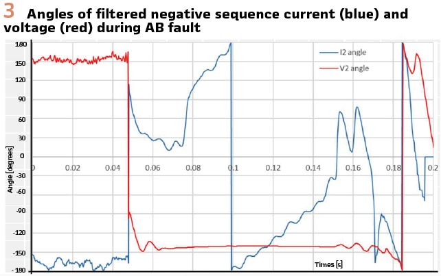
To date, the IBR controlled performance has not matched that of rotating machinery when it comes to asymmetrical fault response. The negative sequence produced is low in comparison to the positive sequence currents. Also, the angle relationship between the negative sequence voltage and the negative sequence output is not purely reactive. In fact, the response can oscillate over time between reactive and capacitive, as illustrated in Figure 3, per the Office of Scientific and Technical Information (OSTI) technical report, “Impact of Inverter Based Resource Negative Sequence Current Injection on Transmission System Protection.” In light of these unique fault characteristics, traditional protection techniques must be thoroughly reviewed for applicability to IBR microgrid fault isolation. Therefore, directional protection elements reliant on phase angle may not operate reliably for IBR microgrid protection in islanded mode.
Other promising state-of-the-art distribution protection methods for distribution applications encompass current differentials, traveling wave, machine learning, and voltage-based detection. However, current differential, traveling wave, and machine learning techniques all have limitations of reliability, cost, or scalability when applied to microgrid environments.
Current differential protection schemes can be sensitive and possibly set at sufficient values immune to IBR control response oddities. However, current differential applications require communication infrastructure for effective deployment, which is not typically seen on existing distribution grids. Current differential applications also require aggregating current information from sources and load contributions at each protection isolation point which very quickly increases implementation cost.
Traveling wave relay protection is fast, it requires very high sampling rates as it relies on detection of wavefronts and the timing of their reflections on the network. This type of protection is newer and successfully implemented on the transmission network. In theory, performance of traveling wave technology could be largely unaffected by the differing IBR microgrid fault characteristics, described previously. However, there are key differences between the distribution network and the transmission network that could affect its performance.
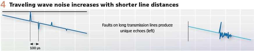
In transmission networks, there are few or no tapped loads and the line lengths are large: this allows for clear differentiations of the wavefronts and leads to adequate timing and fault locations. In distribution networks conversely the distances are short and the tapped loads numerous, making the high-frequency recording of reflecting wave look more like white noise rather than a wavefront that can be timed. This means that the technology in its current state cannot perform adequately without additional components or extensive system modeling, which could result in a high cost of deployment The traveling wave complementary component is most probably machine learning, specifically neural deep network engines. Generating a significant amount of waveform training material from electromagnetic transient simulations may enable a neural engine to recognize the picture of the fault location from a specific fault isolation location, successfully locating faults. However, electromagnetic transient program simulations require a significant amount of computing resources, and by extension, this is also true for training deep neural networks. Traveling wave combined with machine learning is likely a costly method that would encounter significant scalability challenges.
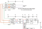
Adaptive relaying is an additional technique that could be successfully applied in islanded IBR microgrids, based on the grid connection status, where more restrictive settings could be applied to the microgrid in islanded vs grid-connected mode. However, studies might be required to analyze the systems states to determine the adaptive settings ranges. Also, it may be necessary to use communications to inform of the network state to all fault isolation locations. Both these requirements have significant hardware and study needs, implying cost and scalability challenges. (Figure 4).
In conclusion, overcurrent, impedance, and distance elements are unreliable in performance, given the fault characteristics of islanded IBR microgrids.
Although current differential, traveling wave, adaptive relaying, machine learning, or some combination of these may be capable of reliably isolating islanded IBR faults, all require costly and complex implementation. Current differential requires advanced relays at multiple points and communications. The traveling wave relays associated with neural networks and machine learning require extensive network location-specific deep training.
Adaptive settings require state estimation studies and communications. Consequently, adoption of these techniques demands a significant cost investment and introduces scalability issues.
The Solution: Voltage Based Detection with Decentralized Timers for IBR Fault Isolation: One solution is a systematic approach to fault isolation in islanded IBR microgrids that relies on undervoltage detection and local timers for operation, in collaboration with existing overcurrent devices on the distribution grid. This patent-pending methodology is under development via a decentralized, time-domain, voltage-triggered distribution line isolation technique that does not rely on communications or costly modeling.
Effective deployment of this technology would require a system of several isolation devices across a distribution power system. Each instance of device implementation combines a voltage sensor and timer to locally trip an isolation device.
When sensing a voltage drop, the controller initiates a time delay to allow any existing overcurrent (i.e., fuse) elements to trip first, for the case of sufficiently large fault magnitudes. If the fuse does not trip, the controller on the device with the shorter timer setting trips first. If the source voltage does not recover, the device closes back. Timers continue to trip and close devices until the voltage stabilizes. When this happens, the latest device tripped stays disconnected. The fault is isolated. This method enables the protection system to overcome the overcurrent technology limitations because the voltage drops reliably in inverter-based systems, even when fault current does not rise appreciably. Therefore, voltage-based protection systems can operate reliably where traditional current-based methods cannot.
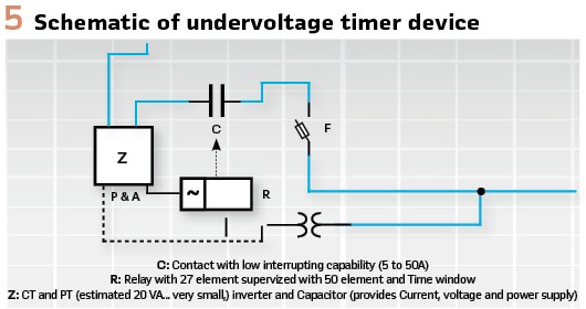
Undervoltage Detection with Time-Based Isolation: Details of Operation. In AC power systems for residential and industrial loads, distribution planners typically use a set of 4 to 6 fuse curves to plan the protection on a distribution feeder. This protection scheme is a robust and straightforward process that allows for quick distribution coordination. Similarly, the patent-pending device can be planned simply and robustly as in Figure 5.
The planning engineer starts by assigning a unique integer to each device on each of the phases. Each integer matches a unique assigned time window. Ideally, the lowest integers are closer to the load, starting with the least critical load and finishing with the most critical load. Then greater integers are assigned to the upstream location where larger loads will need to be disconnected. The duration between each device trip allows the inverters of the system to restore steady-state conditions if the most recent trip successfully isolates the fault.
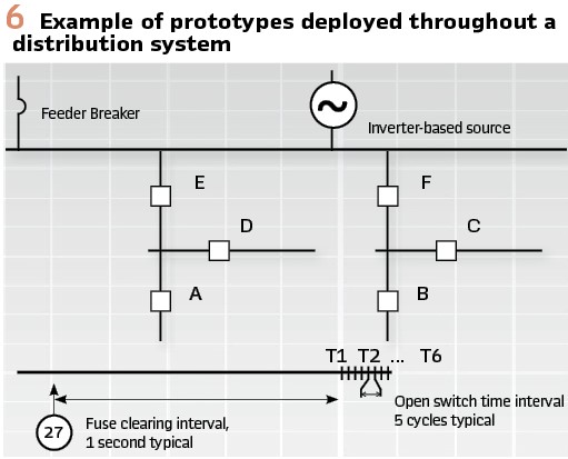
For example, consider Figure 6 where time interval T1 corresponds to the earliest action and a distribution planner employee has associated T1 with device A. T2 corresponds to device B, etc., through the longest time T6 corresponds to device F. If the trip of device A isolated the fault, the portion of the system that remains energized returns to stable voltage levels before time T2. All timers would reset to 0, ending the operation. However, if device A‘s trip did not clear the fault, device A would close back, and the timers would continue to run until time T2. At time T2, device B would trip so that only B is now tripped. If this clears the fault, the portion of the system that remains energized will return to stable voltage levels before T3. This series of trips/closes in the system continues until fault isolation and voltage restoration.
Undervoltage Detection with Time-Based Isolation Advantages: Scalable, Cost-Effective, Cross-compatible. The innovation of pairing under-voltage sensors with timers via a prescribed pattern simplifies the protection planning of the microgrid, aligning it with widespread planning techniques currently used for fuse and recloser deployments. This enhances the scalability of the protection system by leveraging existing Distribution Planning Engineer skill sets, avoiding a need for complex system studies, and eliminating a need for advanced computer hardware in each device.
Localized control of the system also represents an easily scalable microgrid protection design as the new solar, battery, or other sources or circuits are added to the grid. This is because advanced reevaluation of fault conditions and flow paths is not required for each device added to the grid. In addition, costly communication infrastructure and equipment are not required because there is no communication between devices or a master controller.
As an added benefit, this localized design also improves resiliency against cyberattacks that may otherwise infiltrate a wireless communication or a master control system.
Integrating these undervoltage timer devices with existing distribution overcurrent protection technology further enhances its scalability, and allows for integration with existing off-the-shelf equipment, to avail the benefits of both technologies.
The proposed undervoltage technology may be deployed on existing recloser relays or fabricated as stand-alone isolation devices that can optionally be paired with fuses for integration into existing distribution systems. In the latter case, the need to break current at significantly lower ampacity than in traditional grid scenarios also introduces an opportunity for fabrication cost reduction compared to reclosers or switches typically deployed on distribution systems.
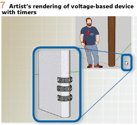
Future Development: The next step in the development of this innovative technology (Figure7) is to begin hardware-in-the-loop testing on existing relay technology within the next 1-2 years, with custom-built prototype manufacturing and small-scale deployment to commence shortly thereafter. Partnerships with high voltage power equipment manufacturers and utilities can help bring such product to market. Core competencies or capabilities in power equipment prototyping, manufacturing, and pilot-scale testing and deployment are especially desirable for making a powerful difference in the future of microgrid fault isolation technology.
Microgrids are likely to be an important part of a more resilient power in the world. This future change will be mostly true if cost-effective methods of fault protection and isolation are available. While the likely high content of IBRs resource mix will challenge current protection philosophies, there are alternatives that while promising are expected to come at a premium cost. The undervoltage, local timer protection method is there to offer a scalable cost-effective solution to enable a future where microgrids add to power system resiliency.
Biographies:

Colleen Konsavage PE is an electrical engineer at Commonwealth Associates, Inc, with a BSE in Systems and Control Engineering from Case Western Reserve University and an MS in Nuclear Engineering from the University of Pittsburgh. She has 10 years of experience spanning nuclear reactor design software, high voltage power transmission, and distribution automation.
Colleen volunteers extensively in her local engineering community in Central Ohio and is the 2022 recipient of the Ohio Society of Professional Engineers Franklin County Chapter Young Engineer of the Year Award.

Sebastien Billaut PE is a manager at Commonwealth Associates. He holds an MS in Mechanical and Electrical Engineering from ESTP, France. He has 29 years of utility-related engineering experience, setting protection relays and power system modeling. He is the patent author for a microgrid fault management technology, and actively participates in industry-wide standards about microgrid, distribution and transmission protection systems. He serves as Chair of the IEEE PSRC WG K29 and D44 and is a member of IEEE PSRC Main and Subcommittees D and C. He is currently contributing to IEEE 1547.x and IEEE 2800.x.