By Eugenio Carvalheira, OMICRON electronics, and Glenn Wilson, Southern Company
Since the introduction of digital relays, it became evident that the test procedures adopted by the industry in the early days of relay testing needed to be adapted. The cause of misoperations were no longer related to mechanical failures or drifts in the relay components, but mostly related to logic, settings or design errors as the last editions of the NERC misoperations studies consistently shows.
Settings-based testing approaches, which in the past were used to calibrate the electromechanical relays or identify relay failures were becoming less important. System-based testing approaches started to get traction, especially for applications like end-to-end testing of communication-assisted protection schemes. For a system-based approach, the test cases are derived from a power system simulation of real-world fault scenarios. With this approach, not only relay failures can be found but also setting calculation errors, logic misconfigurations or communication related issues.
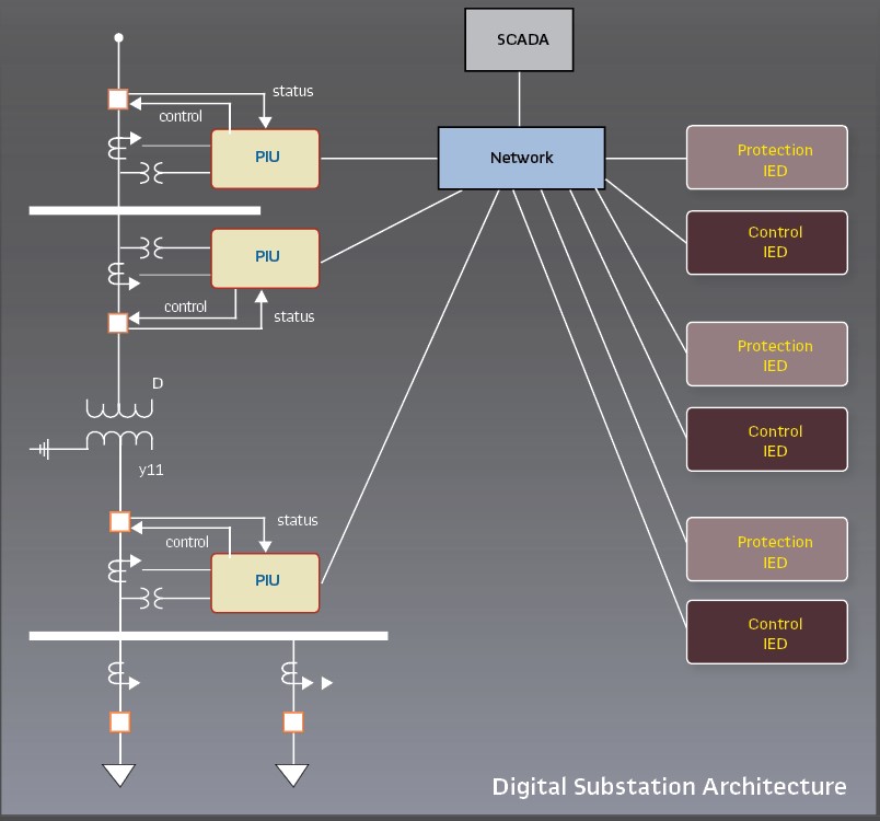
In IEC 61850 digital substations, the advantages of system-based testing are even more obvious considering the distributed nature of typical digital substation designs. One of the big advantages of the system-based testing is that only the system topology (model of the system under test) and the System Configuration Language (SCL) files defining the communication behavior are needed to build-up the test. No specific information from the IED settings is required. A system-based approach should allow for a modular testing under different testing conditions. The system can either be tested entirely or it can be divided into subsystems, where testing of the subsystems would contemplate some level of overlapping. Protection testing can be performed with a subset of IEDs by simulating the Merging Units (i.e. Sampled Values), while the current transformers (CT) and voltage transformers (VT) measurement circuits can be tested as a separate subsystem. This allows for a high level of flexibility during commissioning and maintenance.
Protection Testing in Digital Substations
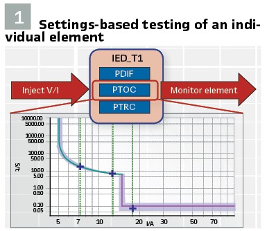
A. Settings-Based versus System-Based Testing: Settings-based testing refers to the task of verifying the operation of individual protection element settings. This test method is traditionally performed since introduction of testing and calibration procedures of electromechanical relays. It is still applicable and valuable during manufacturer development processes and acceptance tests performed by utilities to check element operation against the manufacturer specification. However, this method is no longer enough for commissioning and maintenance to guarantee proper reliability of the protection system. As technology evolved, data show that relay failure is no longer the main cause of misoperations of the protection system. Overall misoperations have decreased, but the reasons why they still occur have changed. Incorrect settings, logics, and design errors along with communication failures account for a big portion of the cause codes as indicated by NERC reports. (Figure 1).
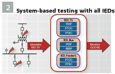
System-Based testing is a testing method based on the simulation of real fault scenarios and verification of the protection system response. Simulations are based on a power system model that represents the application being tested. Ideally, and when feasible, all protection devices utilized to protect the system are part of the test and are simultaneously exposed to the simulated test scenarios. Not only individual elements, but all interaction between them, communication interfaces, and logics are checked. For testing protection of an entire substation simultaneously, the test setup may get cumbersome and demanding. Since interactions are not present between all IEDs in the substation, it is a wise idea to first define which scenarios should be covered within the test procedure and, based on these test cases, decide on a subset of IEDs that should be part of each test case. Each test case subset will contain a limited number of IEDs making the test practical and efficient. (Figure 2).
System-based testing is not a new concept. This testing method has the potential to unveil mistakes made by different stakeholders throughout the whole process of setting a protection system. It helps increase reliability of the system by finding system design flaws, setting calculation mistakes, IED configuration errors, communication failures and wrong logics.
The importance of system-based testing is also covered in other articles that bring examples of errors found during field and FAT tests.
In digital substations, the use of system-based testing principles has an even higher importance due to the high number of communication interfaces and distributed user-configurable logics that are present in such projects. Another benefit to such method is that test procedures can be mostly defined during the system-specification phase, regardless of which exact physical architecture and IEDs are chosen during design. The test cases are based on the primary power system model, on specified functions, and on which test scenarios should be covered. A more standardized test procedure can be achieved with less effort and improved quality. Only little details need to be adapted, like the import of SCL configuration files of involved IEDs, so the test sets can simulate and/or subscribe to the desired messages.
B. Protection Subsystems and Test Coverage: When defining the test procedures and which equipment are to be involved, there are multiple ways the job can be accomplished. If the entire system is to be tested together, this could be accomplished by doing primary injection to CTs and VTs to simulate fault scenarios and observe breaker operations to assess the system response. For testing the protection schemes, this approach is not entirely feasible, as it would require simultaneous primary injection in multiple CTs/VTs. Even a secondary injection to Merging Units is challenging if multiple Merging Units must be involved.
On-site during commissioning, since different groups are working to install and wire the Process Interface Unit (PIU) cubicles in the substation yard, it is challenging to get all equipment available altogether. An overall test would be possible only at the very end of the installation and therefore planning it this way may not be the most efficient choice. For maintenance, it is also common that only the IED is taken out of service while the PIU is kept in service.
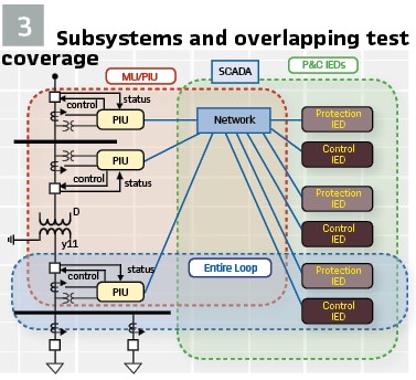
One option is to separate the entire system in subsystems, in which test coverage should overlap each other providing maximum reliability. (Figure 3).
C. System-based Test of P&C IED Subsets: This system-based test has the purpose to verify correct operation of the protection and control (P&C) IEDs when exposed to close-to-real conditions, as for example faults in the system. The devices under test are a subset of P&C IEDs, which are relevant for the scheme being tested, and the communication network infrastructure, i.e. network switches. The test is performed as illustrated in Figure 2 by simulating sampled values and monitoring GOOSE messages published by IEDs. The MUs are not part of the test but are simulated by test sets. As test sets can simulate multiple sampled values streams, more IEDs can be added to the test using less test sets than would be required with analog injections.
Test sets simulate the MUs by using its SCL (usually a cid or scd) configuration files. The test set publishes the same message and behaves the same way as the MU, therefore, the IED communication interface (i.e. configuration of sampled values subscription) is also verified within this test. The correct system response to the simulated scenarios is verified by monitoring the IED GOOSE messages. Any GOOSE interface configured between IEDs, which are relevant to the situation being tested, is also verified in this procedure along with the correct flow of messages through the communication network.
In order to be able to run this test procedure while all equipment is installed, there should be a way to isolate all IEDs under test from IEDs, MUs, and PIUs that are in-service. This is achieved by using the test mode (mode and behavior) and simulation flag test features from IEC 61850. Thus, test sets can simulate MUs while they are connected to the network and IED trips over GOOSE can be neglected by PIUs in-service. This test can be performed as early as during FAT when all devices can be configured and installed in a lab/factory environment prior to shipping to site. This is much easier in a digital substation, since there is no wiring between cubicles and the communication network can be easily installed and connected in the lab/factory for the FAT. The entire test, or a subset, can be repeated during commissioning on-site using the same test plan developed for the FAT.
D. Testing MU/PIU: The MU/PIU cubicles can also be tested during FAT. Wiring from terminals to analog and binary I/O of the device can be verified, as well as the MU/PIU configuration and mapping to sampled values and GOOSE messages. Analog injections can be performed in the MU for verification of its SV output in the network. Of course, values can also be directly measured in the IEDs.
During commissioning, cabling of the cubicles in the substation yard should be verified. Primary injection to CTs and VTs is recommended while verifying sampled values are present in the network and being received by IEDs.
E. Testing the Entire Loop: For the trip circuit, it is recommended to stimulate, at least once, all trips from IEDs to physically operate the breaker. This is a final check and assures the entire system from MU to IED and then to PIU is operating correctly. This test won’t hopefully present any issue, considering the P&C IEDs and MU/PIU were thoroughly tested with the procedures explained earlier.
Case Study: Southern Company Distribution System Design
Within the industry, a common distribution system design is a single transformer with multiple feeders. If system load dictates, this design can be multiplied to include multiple banks serving multiple busses and associated feeders. However, doing so adds increasing complexity to both the construction and testing of these systems, as they often have complicated throw-over schemes to mitigate customer impacts to system events.
Within Southern Company, there was interest to see what the implications would be if this standard industry design was converted to a digital substation. The development of a digital substation standard has the potential for significant cost reductions in terms of wiring, testing and maintenance. In addition, implementing a digital substation design would enable system-level testing as previously discussed in this paper. This level of testing is often impractical for a large station, as it is often difficult, if not impossible to coordinate equipment outages to facilitate the testing. Instead, testing of a system this complex requires multiple, isolated tests to check individual components of the system.
Another advantage of the digital substation approach is the ability to utilize IEDs that can handle multiple protection functions. This further reduces the footprint and wiring requirements, and it simplifies to an even greater degree the logic required to implement these complex restoration schemes, as the number of IEDs needed is reduced.
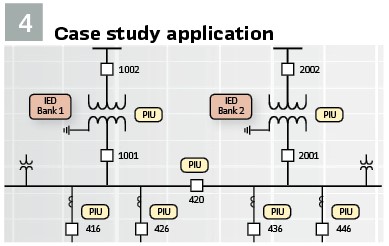
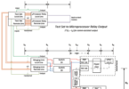
Utilizing a single IED for multiple zones is not common within Southern Company, so multiple topologies are being designed and tested. With one vendor, a hybrid approach is being used where there is a mix of single and multi-zone IEDs, while a single, centralized IED design is being evaluated with another vendor. For this paper, the focus is on the design and testing of the centralized IED design, as shown in Figure 4.
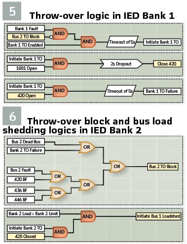
Even in a centralized IED design, there is a need to have system-level coordination for complex schemes like those seen in a Throw-Over (TO). To evaluate this type of system-level test, the logics shown in Figures 5 and 6 were used. For an enabled system, if there was a fault in one bank, the system would try to initiate the TO, as long as there was no abnormal condition on the receiving bus. The abnormal conditions were monitored in Figure 6.
If the TO conditions were met, then the bus tiebreaker would close, picking up the load from the failed bank, as soon as the failed bank had been successfully isolated. However, if the load of the receiving bank exceeded its limit post throw-over, then it would initiate a load-shed procedure.
Case Study: Test Set-up and Results
A. System-Based tests of the Protection IEDs: This section presents the system-based tests performed during the proof-of-concept of the project described in the previous section and shown in Figure 4, involving the protection IEDs of Bank 1 and Bank 2. The test approach is like the one explained previously and illustrated by Figure 2. The system under test is modeled within the grid editor of the testing simulation tool as shown in Figure 7.
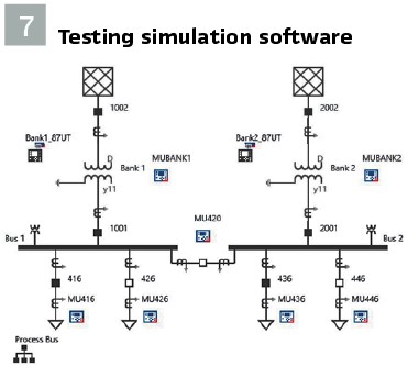
The 115 kV side is modeled as a source while the 13.8 kV feeders are modeled as loads. The model doesn’t require much information to be created, basically some nameplate data for the power transformers plus CT and VT ratios. Sources and feeder loads can be easily estimated. All Merging Units (PIUs in Figure 4) are added as simulated devices. The PIU SCL (cid) files are imported for each simulated device so the test set can publish the respective sampled values. SCL (cid) files from the protection IEDs are also imported to configure the GOOSE signals to be monitored (subscribed) by the test set.
In total, 8 sampled values streams were needed for the defined test cases: 2 streams from each of the bank PIUs (CT HV side + CT LV side and bus voltage); 2 streams from tiebreaker 420; 1 stream from each feeder 416 and 436. Feeders 426 and 446 were not included in the tests presented in this article and therefore their breakers were kept open in the model. To simulate all 8 streams, 2 test sets were utilized that were connected to the communication network and time synchronized from the substation PTP clock. The PC running the simulation software was connected to both test sets via a USB connection.
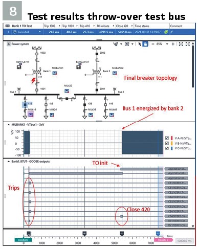
Figure 8 shows the results of the test case for fault in Bank 1 when Bank 2 is energized. Trip of breakers 1002 (HV side) and feeder 416 were measured with the expected time delays as can be observed on top of Figure 8, 23ms and 25.3ms respectively. The trip delay of the disconnect switch 1001 was measured as 40.2ms. It should be observed that 1001 is a disconnect switch, resulting in the need to also send trips to the feeder breakers.
An error was found during this test related to the dead bus condition and TO block signal from bus 2. Bus 2 was sending a block not permitting the throw-over to happen. The problem was found to be in a setting for the threshold of an undervoltage (27 / PTUV) element used for the dead bus calculation of bus 2. The throw-over operated as expected after this setting was adjusted to the correct value. The TO initiate was sent with 4.99s and the close command of 420 with 5.06s, matching with the 5s delay as per the TO logic in Figure 5. At the end of the simulation, the final breaker topology had the fault isolated with 1002 and 1001 opened, while all feeders being supplied by bank 2 with the tiebreaker 420 closed.
B. Verification of PIU Communication: At Figure 3, the concept of subsystems was described with a testing coverage that overlaps each other. In the tests performed at section A, the protection IED schemes were verified. The IED communications were also partially verified by:
- Verification that IEDs subscribe correctly to the PIU sampled values when simulated from the test set. As the test set simulates them based on the SCL configuration file, no issues are to be expected when they will come from the actual PIU (considering the IED is set to the proper simulation mode)
- Verification of transmission and subscription of GOOSE messages between P&C IEDs
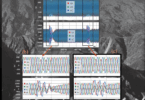
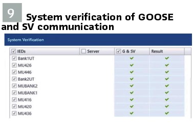
After the PIUs were in-service, a network analyzer was connected to the network to validate all the traffic configured for the PIUs was present in the network. The analyzer sniffs for all sampled values and GOOSE published by all PIUs and IEDs and compares them against the SCL configuration files from engineering design. (Figure 9).
During commissioning, a last test should be performed, which is to verify all cabling between PIU and the primary equipment.
C. Validating the Entire Loop: The last test performed was to validate all interfaces between PIUs and IEDs, referred to as “entire loop” in Figure 3. Analog signals are injected into the PIU, causing a trip GOOSE response from the IED, which is subscribed by the PIU. The test setup was the same as in Figure 7, with the difference that the software is configured to not simulate the sampled values but inject analog instead. One of the test sets was physically connected to each of the PIUs in sequence. In our lab set-up, there were breaker simulators physically connected to the PIU, so it was possible to verify the proper breaker position signaling sent by the PIU via GOOSE. It is not intention of this test to assess the correctness of the protection scheme, but simply to verify all connections are in place. This test should be repeated during commissioning, at least once, preferably with primary injection and actual breaker operation.
Conclusions: It is realized that digital substations bring substantial advantages in the reduction of installation and commissioning time, but with the cost of added complexity in the IED configuration, such as communication mappings and user-configurable logics.
Digital substations also typically present a distributed architecture with many digital communication interfaces and distributed protection schemes. An efficient test methodology is needed capable of unveiling potential errors during project implementation, FAT, SAT and commissioning tests. It is beneficial for this methodology to be defined during the design phase and in alignment with the system functional specification.
A system-based test methodology was applied for the proof-of-concept lab test of a Southern Company digital substation application within its distribution system. Multiple topologies are being designed and tested by Southern Company to assess its benefits and implications on design, commissioning and maintenance.A system-based simulation tool was key in this process.
The system-based test approach proved to be of great benefit, providing an easier test systematic covering all (or a subset of) IEDs in one test. This methodology helped discover incorrect configurations and logics, which could be corrected along the way, leading to a successful result at the end.
Biographies:
Eugenio Carvalheira received his BSc in Electrical Engineering from the UFPE University in Brazil and his MSc in Computational Engineering from the University of Erlangen in Germany. He has 20+ years’ experience in Power Systems Protection, Automation and Control (PAC). He spent part of his career as a Project Engineer responsible for the design, implementation and commissioning of PAC systems at Electrical Substations and Power Plants. He joined OMICRON in 2008 as Training and Application Engineer developing test automation solutions for protection relays, providing technical product application support and responsible for the IEC 61850 training courses at OMICRON. He is currently Engineering Manager for North America based in Houston, TX. He is an active member of IEEE PES serving many PSRC and PSCC working groups.
Glenn Wilson is a principal research engineer for Southern Company. He has 22 years of experience in the electric utility industry. Glenn started his career in Distribution Planning before moving to Transmission Operations where he was a NERC Certified Reliability Coordinator for 8 years. He has worked in the field as Protection and Control engineer, and he served as Transmission Maintenance supervisor for several years before taking his current role within Southern Company’s Research and Development Organization. With both Electrical and Computer Engineering degrees from Mississippi State University, he is passionate pushing the boundaries of digital substation technology and research at Southern Company.