by Walter Schossig, Germany, and Thomas Schossig, OMICRON electronics GmbH, Austria
The “acceptance testing” meant a secondary test at test benches of the vendor or in the lab of the utility. Additionally, an on-site test as well as supervision in the substation have been already common practice.
The “Vereinigung der Elektrizitätswerke Deutschlands” (association of utilities in Germany) published a “relay book” in 1930. A picture can be seen in the June 2018 edition of this magazine. They define values for the overcurrent protection:
- Startup value
- Tripping value
- Operation time at different currents:
- Nominal values
- Double nominal values
- 5..6 times nominal values
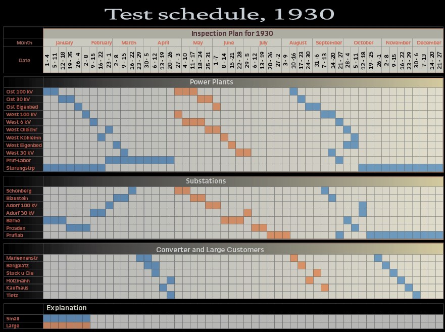
To measure the values a scheme was proposed (Figure 1).
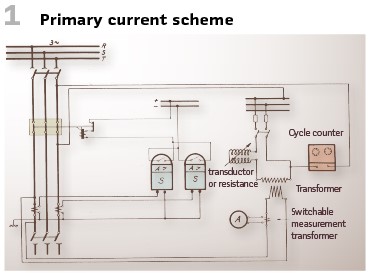
For the secondary current tests (Figure 2) the following steps had to performed:
- Short circuit the measurement transformers
- Open the connectors 1-2 and 3-4
- Control the current value
- Open breaker A
- Close high voltage breaker
- Close breaker A
They also mentioned an “American Shunt Method”. This is how it worked (Figure 3).
- Measure the current at the points A and B when the relay starts up
- Multiply the secondary current with the ratio of windings to calculate primary current
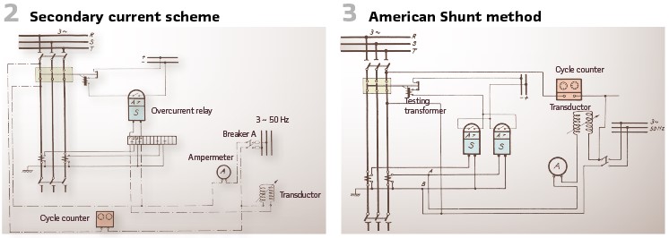
BBC produced a relay test set in 1930. It was mainly used for resistance dependent relays. The current range was between 0 and 50 A, the voltage covered the range between 0 and 220 V. With a weight of 100 kg it came on a trolley (Figures 4 and 5).
The complete setup with accessories and trolley is shown in Figure 5.
The reactance coil and the resistances have been designed in that manner, that after connection to the 220 V or 380 V grid currents and voltages could be produced in magnitude and phase representing short circuits and double earth faults. The switches allowed to change for instance from 2 phase to 3 phase faults. The current could be checked on an amp meter.

The connection to the relay panel was done with test plug. This plug disconnected the measurement transformers and opened the tripping circuits to the oil breakers. Additional lamps visualized the proper trip of the relays (Figure 6).
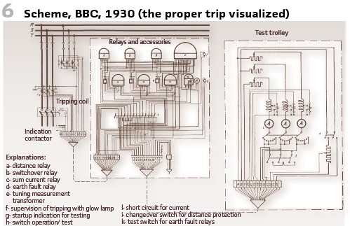
With this setup the entire chain could be tested: Relays, connection to CTs and VTs, circuit breaker, auxiliary connections and even direction setup of the protection.
Siemens & Halske – another vendor, in this case in Germany, developed a test bench (Figures 7 and 8). The voltage and current ranges were like the BBC device.
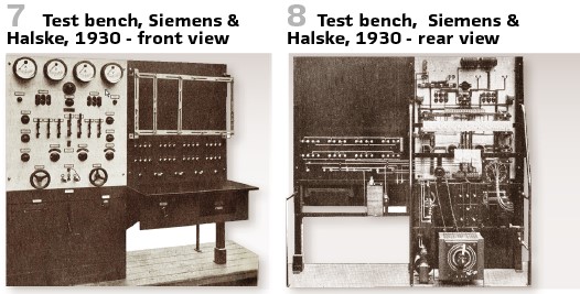
With this setup all kinds of instruments, meters and relays could be tested. It consisted of two parts, one was for operation and one for the measurement. The control panel contained all elements for setup, control and supervision. The measuring panel contained the connection plugs and rails for the measurement instruments to be calibrated.
Via the test switches and had wheel all kind of faults and values could be set up. There have been even possibilities to test bimetal relays as well as DC relays.
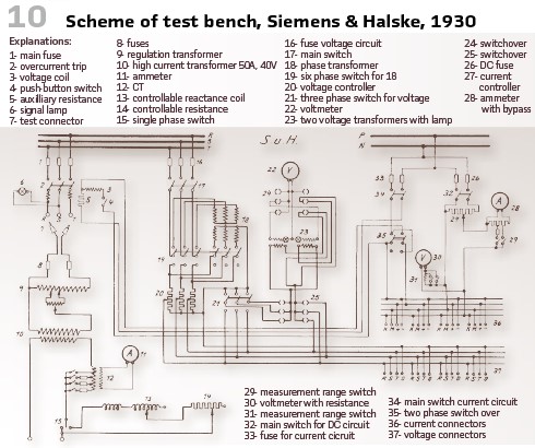
Figure 10 shows the scheme.
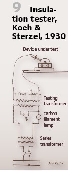
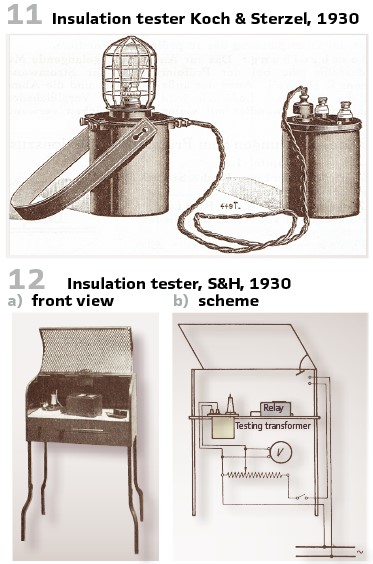
The condition of isolation of relays and low voltage devices had also to be checked during the commissioning in the 1930s. A typical example is the test set of Koch & Sterzel.
The voltage range is up to 2500 V in three steps. The weight was 7.5 kg without accessories and 11 kg with. Figure 9 and Figure 11 show the details.
To test the dielectric strength, the apparatus was connected via high voltage clamps. The low voltage connector was connected to the lamp, which was glowing. Pressing T, the current crosses the series lamp and the primary winding. Since the primary winding of the transformer is like a conductance with high inductance in case of unloaded secondary winding, the biggest part of the connected voltage will be taken by the primary winding of the transformer. The series connected lamp receives small voltage only, the current will be low, and the lamp does not glim brightly. Considering the winding ratio everything can be justified exactly. If the signal lamp stays dark the insulation works fine.
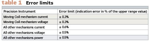
Also, Siemens & Halske tested the isolation of relays and measurement transformer windings.
The voltage range was 0…3000 V. It looked like a conductor’s stand which could be closed by hood. This hood was with a contact which realized safety. The settings could be realized via precision regulator. The voltage was controlled until the maximum value was reached. This was injected for one minute. During this the voltmeter was observed. In case of disruptive discharge, a tripping device took over to disconnect from the grid. (Figure 12 a/b).
For the measurement of the electrical quantities portable instruments have been used.
As a relay tester you had to carry the following devices with you:
- Volt meter
- Am Ammeter meter
- Power meter
- Frequency meter
- Auxiliary measurement transformers.
- They should be Class F devices, what meant error limits as summarized in Table 1.
Additional devices needed could be:
- Isolation measurement device
- Crank inductor
- Rotation field visualizer
- Testing lamp
- Clock
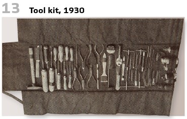
Of course, this was not all, Being a relay engineer in the 1930s meant working like a clockmaker und they had to take with them additional tools (Figure 13).
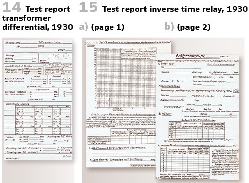
Every test and check had to be documented. Special test report sheets have been available. This report shall summarize all the work done and to be signed by the tester. Even if the examples are in German language, they give an idea how much work this was. The examples are for transformer differential (Figure 14) , inverse time relays (Figure 15a/b).
Also planning of maintenance and testing was huge effort as can be seen in the Table on page 70.
Testing the protection when it was in operation was dangerous. Unintended interruption of power supply could be the consequence. Siemens & Halske (S&H) published in 1931 test recommendation to connect the test set via test plugs. Some cites:
You can try to disconnect the tripping signals. Please be careful because errors would trip the circuit breaker. Because of the danger of tripping some utilities do not tests their relays as often as it should be. This is a bad idea, since the relays must work immediately in case of fault and even after long time of standing still.
To avoid disturbances during the check there might be the demand to switch off the transformer or the line. But this is not possible in a lot of cases. That’s why additional devices are requested to make tests in operation easier. Such flexible solutions are “test plugs.” If they are used the test can be prepared and performed in a convenient manner. Also, the wiring to the CTs and VTs shall be tested. Primary tests are requested but do require huge effort.
This can be done during commissioning only. In operation secondary testing shall be enough. The recommendation was to test the relays every 4 up to 8 weeks. Measurement transformers shall be tested only after disturbances or in case of huge changes in the substation.
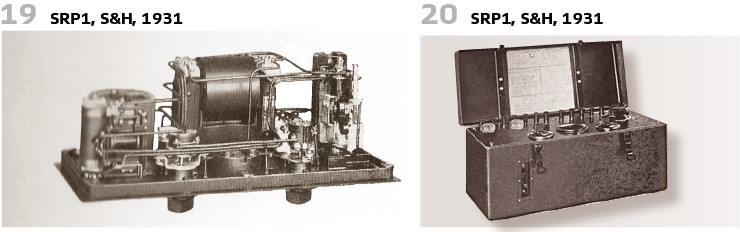
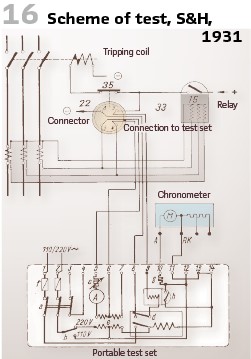
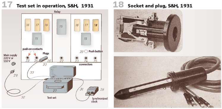
Portable devices are requested, the weight should be maximum 20 kg to make it easy. An example can be seen in Figures 16, 17, 18, 19 and 20.
The test for instance of overcurrent relay (Figure 21) shall be performed as follows:
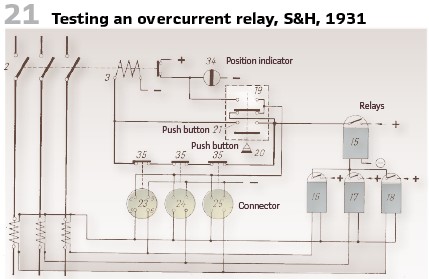
The test setup consists of the push-contacts (22, 23-25), the plug (32), the test box (27) and the synchronized clock (26). The simplest test was timing behavior. Such a test as combination of overcurrent and time relay is visualized in Figure 16. The connector (Figure 18) interrupts the tripping circuit. With a simple turn it will be fixed. Now also the contacts 5-6 and 8-9 will be used. The calibration current is delivered by the test set and injected via the cable (33), the contacts 5 and 6 as well as the current transformer connections. Due to the inductance this works like a block. After a certain time, the relay trips. Due to the open circuits the circuit breaker will not operate. Nevertheless, the trip signal will be received at the contacts 9-8 and the clock will be controlled. The test set itself (Figure 19 and Figure 20) consists of a transformer.
It will be connected to power 110 V or 220 V AC. Fuses and changeover switch are connected. The secondary circuit of the transformer is connected to the terminals 5 and 6 or 5 and 7 via Ammeter and controllable resistance. At the terminals 5 and 6 the voltage (16 V) is available. Terminals 5 and 7 deliver 40 V. The current relay can be connected to 5 and 6, impedance relays to 5 and 7 terminals. With the resistance every current between 4 A and 20 A can be set up.
Finally, also an example from the United States shall be added in this article.
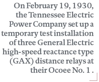
On February 9, 1930, the Tennessee Electric Power Company installed three reactance relays at their Great Falls Hydro Plant. These relays were of the normal speed distance type (LB-1) and were furnished by the American Brown Boveri Company, but were built in Baden, Switzerland, by Brown Boveri, Limited. This was believed to be the first installation of reactance relays in this country. On February 19, 1930, the Tennessee Electric Power Company set up a temporary test installation of 3 General Electric high-speed reactance type (GAX) distance relays at their Ocoee No. 1 Hydro Plant. The Ocoee installation was the first in this country of American built reactance type distance relays.
Another installation of Brown Boveri type LB-2 relays was made at Ocoee No. 1 in February. Another installation of GAX distance relays was made at Centerville substation in March. At the end a total of 54 distance relays of the reactance type worked in the system. In addition to the above, six high-speed distance relays of the Westinghouse impedance type (HZ) are now being installed.
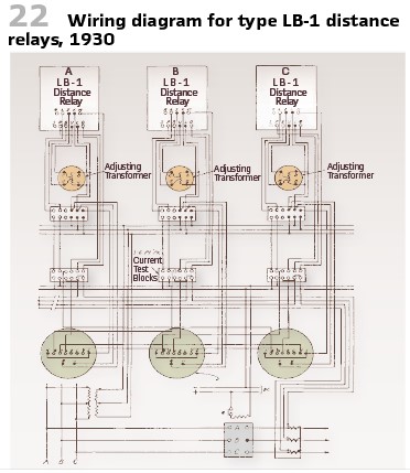
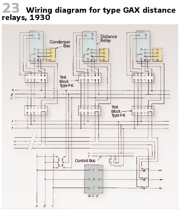
Figure 22 and Figure 23 are typical wiring diagrams for the two types of reactance relays and show how to test facilities preferred by this company have been applied.
In the instructions to the induction time overcurrent relays type IAC11A by GE periodic testing is described in an own chapter. The relay should be given a test and inspection at least once every six months. (Figure 24).
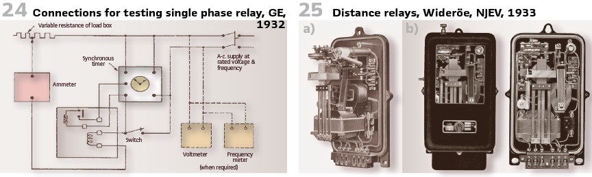
In 1933 it was also the time when Wolf Wideröe, of N. Jacobsens Elektriske Verksted a/s, Oslo (Norway, NJEV) performed first tests with the new distance relay. At a line in Vestfold tripping time of 2 periods could be observed. (see Figure 25 a and b).
There is more to tell- in the next issue of the magazine.
info@walter-schossig.de www.walter-schossig.de
thomas.schossig@omicronenergy.com
Biographies:
Walter Schossig (VDE) was born in Arnsdorf (now Czech Republic) in 1941. He studied electrical engineering in Zittau (Germany), and joined a utility in the former Eastern Germany. After the German reunion the utility was renamed as TEAG, Thueringer Energie AG in Erfurt. There he received his master’s degree and worked as a protection engineer until his retirement. He was a member of many study groups and associations. He is an active member of the working group “Medium Voltage Relaying” at the German VDE. He is the author of several papers, guidelines and the book “Netzschutztechnik [Power System Protection].” He works on a chronicle about the history of electricity supply, with emphasis on protection and control.

Thomas Schossig (IEEE) received his master’s degree in Electrical Engineering at the Technical University of Ilmenau (Germany) in 1998. He worked as a project engineer for control systems and as a team leader for protective relaying at VA TECH SAT in Germany from 1998 until 2005.
In 2006 he joined OMICRON as a product manager for substation communication products. He is author of several papers and a member of standardization WGs.