by Walter Schossig, Germany, and Thomas Schossig, OMICRON electronics GmbH, Austria

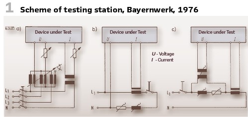
In the 1970s, the Bayernwerk AG, BAG (Western Germany), used a programmable, automatic testing station for distance protection (Figure 2). To be able to test distance relays exhaustively, but time and labor saving, the automatic testing station was developed. It was in operation successfully for a long time.
The general requirement was to allow proper testing of all distance protection devices used at this time. Some older relays really demanded a lot of power, while the modern relays already came with short operating times. There should be no retroactive effects, and the impact of harmonics or other topics had to be considered. The setup should be easy to use and limit the demand for additional devices and space.
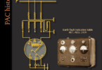
The scheme shown in Figure 1 explains the possibilities. The first one was to have the circuits for voltage and currents separated. The values could be defined as wished, as well as the phase shift (a). The other variant (b) was to produce voltages and currents out of a replica of the line. There was the possibility to remain the voltage connected to the device under test continuously. To simulate the short circuit, an additional current was injected and connected to the current circuit of the relay. In c) the device under test is suplied with voltage drop as well as current.
The third variant was recognized as the optimal. The testing current is injected into the current circuit of the distance protection. Resistances in series cause the voltage drop. The complex value of the resistance represents the line’s replica and allows a setup of the R/X ratio. It was created as 4 phase setups, supplied by the available 3 phase 380 V grid.
All elements were combined in a L-style setup (Figure 2).
With the automatic test 32 measuring points could be programmed, so for every device a maximum of 192 shots were possible. For every measuring point, seven steps of the measurement impedance could be used. In addition, testing current’s nominal value as well as the stages to adapt them (between 0.5 and 4 times of nominal value) could be programmed. In addition, the direction could be defined. In every step six different faults could be tested. In case of issues, the test could be repeated. The time needed for a single relay’s test was between 15 and 25 minutes (also depending on the operating times of the relays). To repeat the tests in case of replacements, a reference characteristic could be saved. Also, documentation was possible with a printer connected. Differences from the reference characteristic were printed in red color.
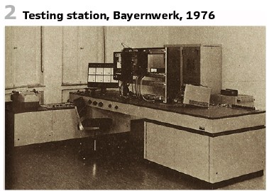
One of the leading technical universities in the GDR was the TU Dresden. For teaching and research purposes, they used a dynamic network model developed by teachers, graduates and students (Figure 4).
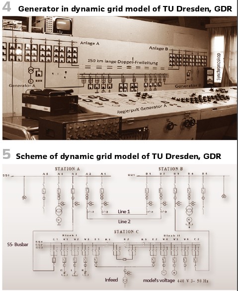
In addition to the double line with the parameters of a 150 km long 220 kV double overhead line, a generator is connected to each of the two stations (Figure 5). Station C has the task of connecting the rigid network to one of stations A or B and connecting the generator to the other station so that it is operated via the line on the rigid network. Station C also allows selected preloads to be connected to the stations. The two model generators are powered by model turbines (Figure 3). DC motors were used with controllable rotor resistors that made speed control and thus synchronization possible. The switching devices are controlled realistically using control discrepancy switches. The mimic diagram contains the measuring devices and the display of the switch positions. A synchronoscope is switched on to synchronize the generators. A mobile fault cart is available for modeling single- and multi-pole transverse faults as well as longitudinal faults, which can be driven to the desired location on the overhead line. The faults were switched with contactors and the timing of combined faults is controlled by a switching drum. The generators were protected with block differential, earth fault and overcurrent protection and the lines with distance protection RD11, EAW, as well as modified SD4, AEG, and R3Z24, Siemens.
The scales used:
- Time 1:1
- Voltage 1: 500
- Current 1: 20
- Power 1: 10000
- Impedance 1: 25
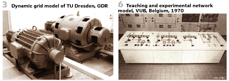
The teaching and experimental network model of the Free University of Brussels, VUB (BE) is shown in Figure 6 and Figure 8.
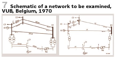
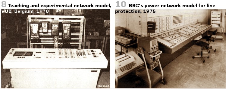
Figure 7 shows a network to be examined.
The Swiss BBC presented a power network model for line protection in 1975. When implementing the model, the following goals were set:
- The testing facility should be designed to meet the needs of line protection. The simulation of large-scale network images with multiple lines and feeders was therefore ignored. They limited themselves to two lines, which were operated in series or parallel and formed a so-called T-line pattern with three feed points interconnected
- The model should be as realistic as possible for as many operating cases as possible recreate. This requires at least two feeds, which are independent of each other are required
- All possible line errors must be switched on in a controlled manner Operating currents should be on the lines
- Different circumstances, also for control operations should be included. It must be possible to switch each phase separately
- The tested protective devices are via suitable current and voltage transformers connected and must have an impact on the model
- The performance of the testing facility should be sufficiently high be so that the examinees’ own consumption and the measuring device can be neglected
- The structure of the model should enable all changes in experimental conditions very quickly and easy
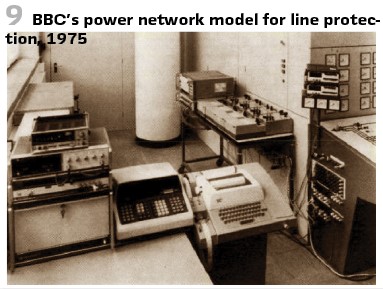
A network model that meets these guidelines is in place and in its basic configuration was for two years in the development department of BBC (Figure 9 and Figure 10). Its basic structure can be seen in the diagram in Figure 12.
Main data:
- Construction: Three-phase with ground return for rigid grounded or isolated networks, consisting
- Consisting of two lines and three supply impedances
- Feed: Rigid from the mains via 860 kVA test transformer
- Rated voltage: 1000V
- Frequency: 50Hz
- Rated current: 10A.
- Continuous current: 20A
- Maximum Test current: 200 A for 0.5 s
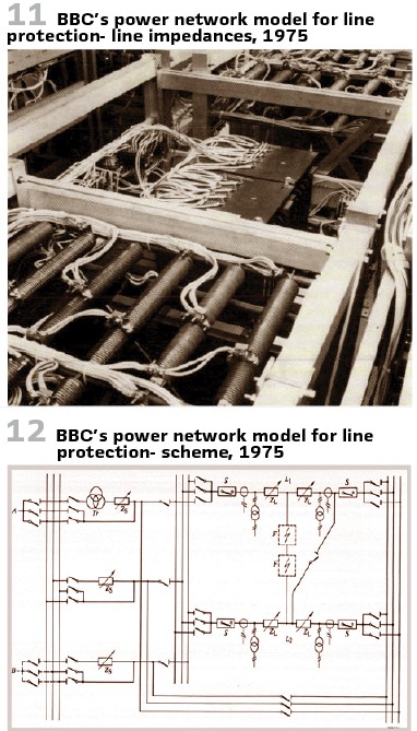
The line replica is shown in Figure 11 and Figure 14.
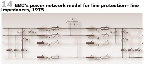
In 1978, BBC had provided protection for around 400 busbar systems over the past twelve years. These protective devices were all customer-specifically designed according to the technical conditions of the systems. Due to the large volume of over 50 such protective devices per year on average, an economical and efficient testing procedure became necessary. The knowledge of so many system configurations made it easier to develop a universally applicable testing device to build. A system simulation enables the testing of protective devices for systems with 1 to 4 busbars and a maximum of 40 outlets. (Busbar disconnectors and couplings are taken into account.) With a minimum of input into the control unit, all measurements and logging can be carried out using a universal program (Figure 13).
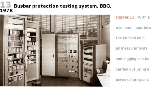
Figure 13 shows the entire setup. The following units can be seen from left to right:
- two-field test plug-in module
- busbar replica
- automatic cabinet
- control unit
Since the device under test is completely connected (planned reserve departures included) to a replica system, realistic conditions can be reproduced. This results in refined test procedures and thus a significantly increased test depth. All electrical connections between the busbar replica and the protective cabinet are made using pluggable test cables. This allows the device under test to be connected quickly and easily. The control can be manual or automatic.
The automatic part of the system is mainly used to measure the response and tripping values of the protective device. At the same time, the measured Values are logged and evaluated. Automation makes it possible to record more measured values, i.e., to carry out a more thorough test than with manual testing. The devices installed in the automatic part are interconnected by an instrumentation interface bus (IEEE 488), and their functions are controlled by a computer programmable in Basic. Of course, this computer also takes over all control, evaluation and logging tasks. The following devices are installed: a digital multimeter, a digital counter, a measuring point switch with 80 channels and a static power source. Special adapter clips take the measurement signals from the protective device and prepare them for transmission to the measuring devices. A static power source, which can be controlled both by the computer and manually, is used to generate the test variable. It is phase and frequency synchronized with the power sources in the busbar simulation. Either 0° or 180° phase position of the current to the reference phase can be selected. The phase is reversed when the current crosses zero, which enables reliable tripping time measurements. A function generator is integrated into the current source, which generates the current curve of saturated converters with a variable saturation angle. In normal operation, the phase can also be rotated by ± 60°. These additives are intended for non-automatic operation and enable testing of the protective device under conditions such as those that can occur with external short circuits with extremely high currents and transformer saturation in busbar systems.
Figure 15 shows the setup. (See the explanations inside Figure 15).
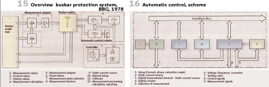
Figure 16 shows the scheme of automatic control. (See the explanations inside Figure 16)
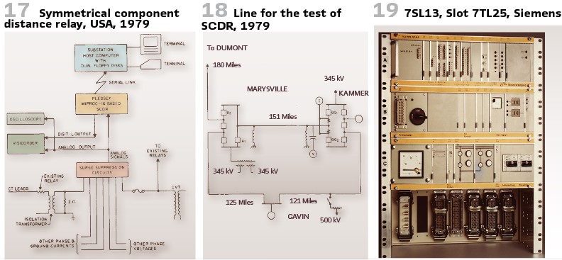
It was in 1979, when in the US a micro-computer based Symmetrical Component Distance Relay (SCDR, Figure 17) was tested on 151 mile line 765-kV-Leitung Kammer-Marisville (Figure 18).
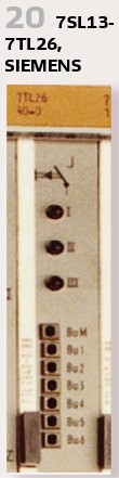
SIEMENS released a static line protection 7SL13. It came with internal testing possibility, to be used for commissioning and for disturbance investigation. To test the directional element of the protection, the slot 7TL26 contained 3 buttons (I, II, and III). Pressing one of them, the startup logic starts by simulating a single phase fault. At the same time the tripping output was blocked. The directional element is using the load current (must be at least 10% of nominal current) to decide on the direction. If the current flows in the other direction, this must be indicated properly. (Figures 19, 20).
The measurement board came with 7 measurement sockets. The socket M is the base potential. “Bu 1” is connected to the static output signal of the directional element, “Bu2” is the trip of the distance protection. “Bu3” contains the rectangle voltage (in sync) for the estimation of direction. “Bu4” got the positive square waveform voltages of the difference pointer ΔU. “Bu5” is used for the reference phasor, “Bu6” is general startup. BBC’s distance relays LI6, LIU6, and LIZ6, came in 19” racks (Figure 22).
The slot WXW411 contained the signal processors for the measurement values. The buttons “Betrieb (Operation) – “0”- “Test”). The zero current compensation could be defined. The distance protection values could be set on a matrix. Tuning elements and pins were used for the angles and measurement ranges. At the MPT the times, overcurrent startup could be set and were indicated. Also, a reset was possible.
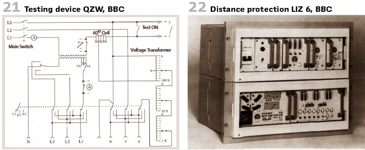
Another variant was the distance relay LIZ613de. As a testing device the QZW by BBC was available (Figure 21).
As a replica of the line to be protected, a 60° coil was used. A built-in current transformer allowed the adaptation to the nominal current. The voltage could be controlled.
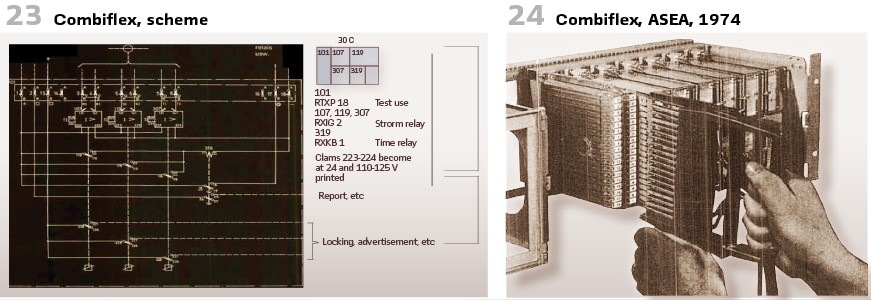
The Swedish ASEA introduced the COMBIFLEX-Systems in 1974.
It came with a special handle RTXH 18 (Figure 24) at the test card RTXP 18. To avoid opening the CT connection, a short circuit element RTXK was on the back (Figure 23).
info@walter-schossig.de www.walter-schossig.de
thomas.schossig@omicronenergy.com
Biographies:

Walter Schossig (VDE) was born in Arnsdorf (now Czech Republic) in 1941. He studied electrical engineering in Zittau (Germany) and joined a utility in the former Eastern Germany. After the German reunion the utility was renamed as TEAG, Thueringer Energie AG in Erfurt. There he received his master’s degree and worked as a protection engineer until his retirement. He was a member of many study groups and associations. He is an active member of the working group “Medium Voltage Relaying” at the German VDE. He is the author of several papers, guidelines and the book “Netzschutztechnik
[Power System Protection]”. He works on a chronicle about the history of electricity supply, with emphasis on protection and control.
Thomas Schossig (IEEE) received his master’s degree in electrical engineering at the Technical University of Ilmenau (Germany) in 1998. He worked as a project engineer for control systems and as a team leader for protective relaying at VA TECH SAT in Germany from 1998 until 2005.
In 2006 he joined OMICRON as a product manager for substation communication products. He is author of several papers and a member of standardization WGs.