by Walter Schossig, Germany, and Thomas Schossig, OMICRON electronics GmbH, Austria
All the time we tried to investigate the history standards. We do not know exactly, when the work on ASA C37.1-1937 “ASA American Standard for Relays Associated with Power Switchgear” started. But it was in 1949, when the relay committee recognized need to define the isolation levels for protection relays and recommended to rework the standard published in 1939. The relay isolation in the factory should be tested with 1500 V, the field test shall be done with 1125V (75%). The standard covered all relays directly associated with power switchgear. It contained service conditions, definitions, ratings, heat and power limitations, limitation other than heating, and dielectric tests.
In 1947 the Relay and Switchgear Groups were separated from the Protective Devices Committee and given the status of a Committee under the Power Group. The Protective Devices Committee remained as the home for Lightning Protection. It is not known at this writing if there were other functions covered by the Protective Devices Committee at that time. Following WWII there was a very rapid expansion of the electric power system. The growth rate approached 10% per year. Many new engineers were entering the work force. This expansion was accompanied by a need for guidance of these newly minted engineers. It was not unusual for their mentor to suggest that they should avail themselves of the AIEE Standards. The electrical equipment manufacturers, electric utilities and educators were active participants in the Protective Devices Committee, the Relay Committee, the Switchgear Committee, and the T & D Committee. The members were encouraged to write Transaction Papers and prepare Technical Reports. Most of this effort was devoted to the development of application document and discussion of issues affecting the standards.
By 1949 it became apparent that the demand for energy would require an increase in the transmission voltage for the electric power system. The voltages were increased from 69 kV and115 kV to 138 kV and 230 kV. With the higher transmission voltage, there was an accompanying need to review existing switchgear standards and insulation coordination standards. It was recognized in 1949 that consideration need to be given to insulation flashover deionization time when applying high speed reclosing. This was discussed in an AIEE Transactions paper by Boisseau, Wyman and Skeats. The recommendation in this paper lead to change in the application guide for applying circuit breakers to high voltage transmission lines. Work done by Bryon Evans and C. Lee Kilgore based upon investigations done at Grand Coulee Power Plant on the 230 kV transmission lines indicated that standards for testing and applying AC Circuit Breakers were not adequate and needed to be revised. Testing for the interrupting capacity of the circuit breaker needed to be changed from the use of asymmetrical current to a symmetrical current basis. They introduced the concept of the need to test a breaker for its Transient Recovery Voltage (TOV) capability. Guidance was provided on the need to limit TOV to 2.5 per unit. Similarly, it was recommended that the maximum out-of-phase switching test voltage needed to be specified. They recommended 2.5 per unit. Another important recommendation was to relax the maintenance requirement in the standard from an inspection after every two operations to an integrated kVA that was 10 times the breakers declared interrupting rating at rated capacity. Up until the time of the AIEE and IRE merger, use was made of AIEE Transactions paper to present and discuss proposed changes in the circuit breaker standards.

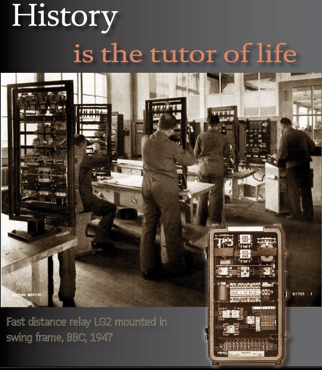
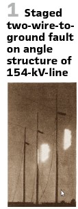
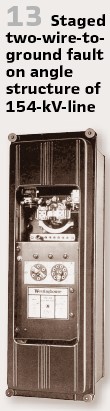
It was in 1943, when Minard, Gow, Wolfe, and Swanson reported staged fault tests of relaying and stability on Kansas-Nebraska 270-mile 154 kV interconnection. 22 staged fault tests were made online and terminal systems to check the between fault characteristics of new long-line relays. The goal was to differentiate faults and high-power swings. Observed power swings and relay performances have been compared with theoretical aspects and predictions.
Figure 2 shows the impedance circle diagram of the interconnection as “seen” by relays at Kansas terminal together with characteristics of relay units. It is interesting to see the oscillograms made at this time. Figure 3 shows an example for two-phase to ground fault on 154 kV line near Nebraska end with 30000 kW received in Kansas. Even the power flow was recorded during the tests (Figure 4). Also, impressive pictures were taken (Figure 1).
A typical relay at this time was GE’s CEX relay (Figure 5).
BBC tested generator protection relays in 1943. The testing voltage was 110/64 V, taken from a testing transformer. Connected via resistances, a single one for every relay. They had the dimension to handle the power. A board disconnected the tripping circuits and switched them to “indication” mode. So, the proper operation of the relay could be observed. Doing so, generators in operation could be tested. Additionally, the entire chain including measurement transformers should be tested from time to time, with additional short-circuit elements.
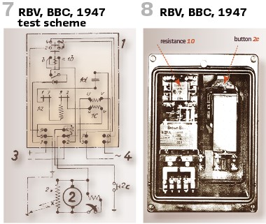
Rotor earth fault relay RBV had to be tested during commissioning. To do so, they checked the rotating armature of the maximum current relay 1a (Figure 7) if it is rotating smoothly. The spring, operated by a pen, had to bring the nib 7 back. The contact mechanism itself was calibrated in the factory properly and should not be tuned.
Pushing the button 2c (Figure 8) the earth potential was connected via resistance 10 to the excitation system simulating rotor earth fault.
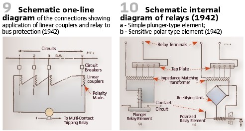
It was in 1942, when Harder, Klemmer, Sonnemann and Wents published Transaction paper on linear couplers for bus protection. The idea was to present a scheme of bus protection, offering advantages in simplicity, speed and size using so called linear couplers. Those have been air-core mutual reactances in place of current transformers, to solve the problem of saturation and to provide a linear relationship between secondary voltage and primary current. The coupler secondaries for a given bus are connected in series loop with the relay. When the currents entering and leaving the bus are equal, the net induced voltage in the relay loop is zero. For a fault on the bus, however, the net induced voltage, proportional to the fault current, operates the relay (Figure 9, Figure 10).
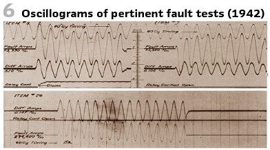
Combination tests were made to prove it was practical and safe to use simple overcurrent-type high-speed relay with linear couplers for differential protection, regardless of the numbers of circuits in the protected zone. This meant demonstrating that the couplers were linear in fact and practically unaffected by any stray fields produced by other circuits (Figure 6).
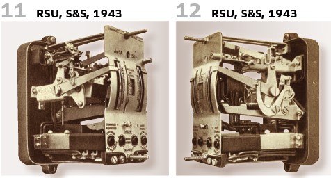
Typical secondary relays at this time looked like the RSU (Figure 11, Figure 12), produced by Sprecher and Schuh.
Some vendors produced for independent overcurrent protection single relays as the RSU device. The vendor also described the testing in the manual: Periodic revisions in the utilities require testing of current and time settings during operation. For a three-phase protection only the device under test will be out of service during the test, the other phases remain protected. The secondary circuit of the CT has to be short circuited. The power source and the chronometer must be connected. At the end of the test all clamps must be moved into the other direction.
The book “Silent Sentinels” published by Westinghouse in 1949 and describing the protective relays was mentioned in the past already. The type of HCB Pilot Wire relay used positive and zero sequence currents to operate the single relay and to obtain protection for all types of phase and ground faults using only two pilot wires (Figure 13).
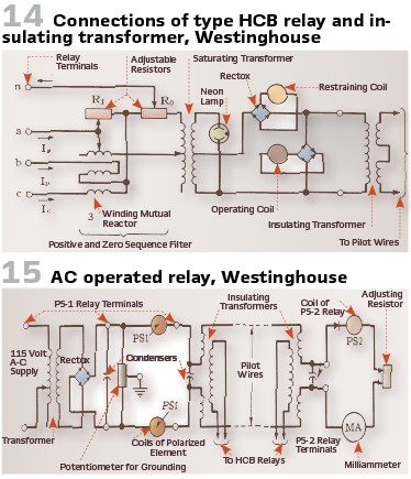
A schematic diagram of connection of the type HCB relay and insulating transformer is shown in Figure 14. Figure 15 shows the schematic diagram of application of an AC operated type PS-1 supervisory relay with a type PS-2 supervisory relay.
The linear coupler relays LC-1 and LC-2 utilized polarized relays and have been released in 1942. The single pole carrier relay and auto recloser for the type HKB relays are available since 1944.
The 1940s have been the decade when pilot wires became widely used. Just looking into 2 additional Transactions papers. Harder and Bostwick published the paper on protection of pilot-wire circuits in 1942. The recent increase in use of high-speed pilot-wire circuits for the protection of important circuits has accentuated the need of better understanding of the pilot-wire protection system (Figure 16).
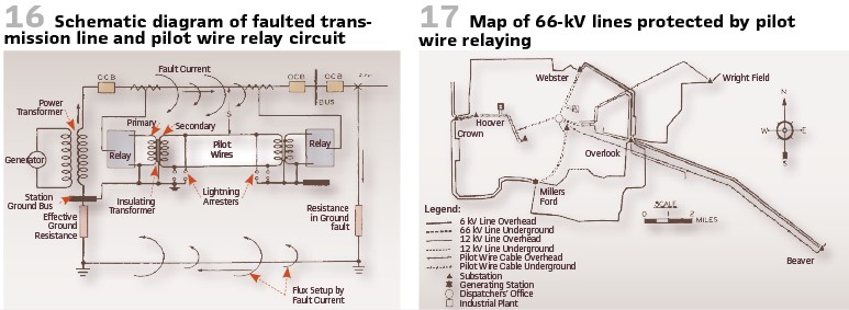
Also, Killen and Law investigated the protection of pilot wires from induced potentials. The pilot wires were used for relay protection of 66 kV transmission lines on the system of the Dayton Power and Light Company in several cases parallel 12 kV distribution feeders (Figure 17, Figure 18).
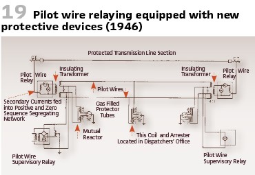
To protect the pilot wires new protection devices as shown in Figure 19 could be used. Field tests showed the proper operation. Faults were cleared satisfactorily.

The Swiss company Oerlikon occurred several times in this series. In 1941 they introduced “Limitherm” relays. This thermal overload protection was invented for smaller motors originally. But it was extended to machines, cables, and transformers since also those assets should be used as good as possible but without reaching a temperature damaging the asset or its isolation. The relay BiT (Figure 20) was for switch panel mounting, the size was the same as for other secondary relays. It could be easily adapted to the thermal curve of the object to be protected. The power consumption was rather low, so it could be powered by the CT. The object to be protected could be supervised permanently while displaying the thermal load factor in percent of the nominal current. A trailing pointer showed the maximum value reached. When exceeding the maximum value, the device tripped. The environmental temperature could be compensated. In case of using coolant, the load could be increased. An additional short circuit protection was available. Finally, testing was easy.
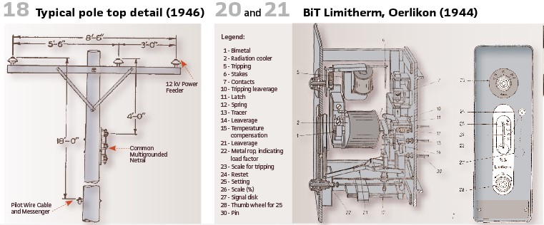
The testing could take place again in service. The front plate could be removed, the current connection remains on the back. To check the contacts, two screw nuts had to be moved. While unplugging (Figure 21), the CT connection was short circuited. The tripping circuit could be tested, while setting the value of element 23 to “0”- the relay tripped immediately.
To test with “foreign” current, a spare relay should be used during the test. Further maintenance was not needed since everything was protected by the housing.
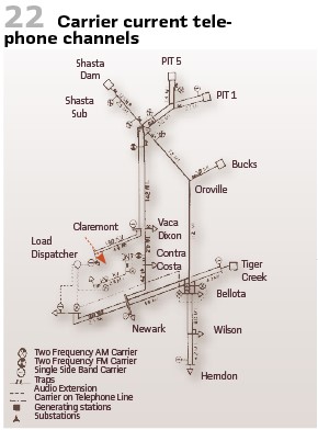
Also, Power-Line Carrier-Current equipment was already in use at this time. Miller and Prud’Homme published the Transactions paper in 1946. They performed field tests made on the power line carrier current telephone system of the Pacific Gas and Electric Company, covering both amplitude and frequency modulated equipment. At this time the telephone system on its 230-kV-transmission line system was in operation for 23 years already. (Figures 22/23).
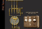
BBC in Switzerland used swing frames in the production of the high-speed distance relays LG (title picture). Efforts aiming at standardization of relay constructional forms have also led to the manufacture of high-speed distance-relay equipments for flush mounting. These equipments are so designed that good accessibility to the individual component relays is ensured. After opening the front cover, the frame on which all relays are mounted can be swung out and clamped in the open position. Maintenance work on the relays can then be carried out in exactly the same way as in the case of the semi-projecting pattern. Another innovation, which appreciably simplified the work of checking disturbances, is the inclusion of a group of indicators in the distance-relay panel. These indicators (Figure26) replace the signal flags of the auxiliary contactors. The concentration of the signals in one unit allows greater freedom in the choice of the site for the installation of the distance-relay equipment. If difficulties are encountered in mounting the equipment in the control room on account of the large space requirements of the distance-relay panel, it is quite sufficient to install the indicator unit there alone. It may be mentioned that the indicators are reset electrically.
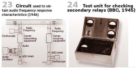
The test set for operational checks of secondary relays by BBC from the year 1945 is shown in Figure 24. Primary voltage was 220 V, secondary voltages 3-180 V, secondary currents 30-105 amp. The apparatus was ideally suited for small tests on account of the ease with which current and voltage can be regulated. The regulating resistance was protected from overloading by a built-in switch with thermal releases.
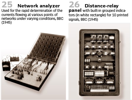
In the case of electricity supply undertakings, the engineers responsible for power supply and distribution often required to know exactly the magnitude and direction of any short circuits which may occur at any points in their networks. In the same way it is necessary for the Company’s engineers to have a clear understanding of the short-circuit conditions in a network if the correct protective equipment is to be provided. The predetermination of short-circuit currents and their distribution is generally difficult and, in the case of networks with a high degree of interconnection, means a long and tedious calculation. A network analyzer (Figure 25) has therefore been developed which is based on well-known principles and permits the conditions prevailing in any network to be reproduced in miniature, so to speak, by adjustment of its impedances, and the short-circuit currents to be ascertained. With carrying strap and weight of 9.5 kg the device was easy to carry.
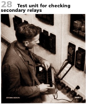
Another interesting test set by BBC was the “Prüfapparat C” (Figure 28).
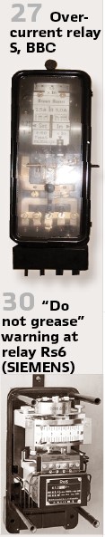
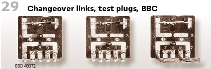
This test set was connected to AC source 220 V (40-60 Hz). Current and voltage could be regulated via step switch at the secondary side of transformer (90 VA continuous power), and via sliding resistance at the primary side for fine tuning. The maximum permanent current was 30 A, maximum voltage 180 V. The sliding resistance is protected against overload by temperature switch. The tester receives a warning immediately. Since the thermal inertia is small the device could be used after overload immediately. For short tests with increased power resistance and temperature the switch could be bypassed and the full short-circuit power of transformer was available. The main switch switches on the timing device of any vendor. For measurement switch panel devices have been used, different measurement ranges have been possible (1; 5; 15; 40 A). The short circuit was realized automatically. The added resistance was built in. For accessibility BBC equipped their overcurrent relays (Figure 27) with changeover links, test plugs and screw plugs (Figure 29). The different modes to be chosen are normal operation, relay out of service and testing in operation.
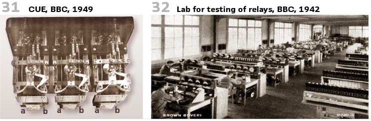
In the 1940s the workshops have been enlarged dramatically. Figure 32 shows a new lab with testing rooms. All relays have been tested intensively.
In the relay labs very often, clockmakers could be met. They have been used to oil everything, especially the bearings. Since relays must work seldomly, compared with clocks, very often gumming was the result. To avoid this and to warn the colleagues a relay was equipped with the warning “do not grease” (“Bitte nicht ölen” in German, Figure 30).
Nevertheless, the testing engineers had to be as sensitive as clock workers. Checking the manual for the BBC’s generator earth fault relay CEU we can read that a mechanical check belongs to putting in operation: “The rotating system of the relay must work frictionless. This can be tested by jolting contact arm a in Figure 31. In rest position the contacts b are open. The clearance of the rotating system must be less than 0.2 mm. Is the clearance bigger, the system is vibrating in normal operation. To justify the upper bearing screw could be used.
If test switch was available, the relay could be tripped in operation. Rotating the test switch from position “Betrieb” (operation) to “Prüfung” (test) interrupts the tripping circuit already in intermediate position. A red lamp indicated that protection is out of service now. Instead of operating the circuit break lamps have been switched on now.
When switching back to normal operation, the test switch should remain in intermediate position for some time, to guarantee falling back of the relay. This test was performed once a month.
We started our journey to the 1940s in the US, so let’s finalize here as well. It was Sonnemann who published a paper in 1949 on “Novel test circuits for protective relays”. For him it was obvious, that in the test, calibration, checking, and setting of protective relays, and the determination of their characteristic operating curves it was necessary to apply to the relays the quantity or quantities which are expected to operate them. When the quantities are rather simple, such as a single variable current value, there was no special problem, particularly in the laboratory. When two or more quantities are involved, the problem becomes more complex, particularly when the phase angle between these quantities must be known or controlled. Of course, special circuits and equipment were common practice at this time already. He delivered proposals to use the load current and voltage as delivered to the relay from the instrument transformer for testing purposes. He did his trials with type HCB pilot wire relays.
info@walter-schossig.de www.walter-schossig.de
thomas.schossig@omicronenergy.com
Biographies:

Walter Schossig (VDE) was born in Arnsdorf (now Czech Republic) in 1941. He studied electrical engineering in Zittau (Germany) and joined a utility in the former Eastern Germany. After the German reunion the utility was renamed as TEAG, Thueringer Energie AG in Erfurt. There he received his master’s degree and worked as a protection engineer until his retirement. He was a member of many study groups and associations. He is an active member of the working group “Medium Voltage Relaying” at the German VDE. He is the author of several papers, guidelines and the book “Netzschutztechnik [Power System Protection].” He works on a chronicle about the history of electricity supply, with emphasis on protection and control.

Thomas Schossig (IEEE) received his master’s degree in Electrical Engineering at the Technical University of Ilmenau (Germany) in 1998. He worked as a project engineer for control systems and as a team leader for protective relaying at VA TECH SAT in Germany from 1998 until 2005.
In 2006 he joined OMICRON as a product manager for substation communication products. He is author of several papers and a member of standardization WGs.