by Walter Schossig, Germany, and Thomas Schossig, OMICRON electronics GmbH, Austria
For the design and testing of relay protection systems the recommendations of the vendors as well as national and international rules have to be applied. Additionally, also the results of disturbances had to be considered. Let’s have a deeper look into the 2 parts of Germany existing in 1953- the Federal Republic of Germany (FRG) and the German Democratic Republic (GDR). At the same time, in the year 1953, guidelines for generator protection have been published.
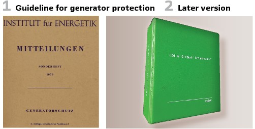
In Eastern Germany this was a technical report (#18, published by the scientific center for energy technology called IfE (Institut für Energetik) in Leipzig at the 26th of November in 1953. Figure 1 shows the 5th edition.
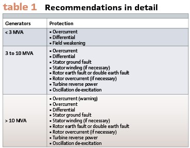
The general coordinator was, Rudolf Ulbricht, head of committee (Fachunterausschuss FUA) at the engineer’s organization KDT (Kammer der Technik, successor of VDE in GDR. The guideline covered the choice and setting of generator protection relays. Table 1 shows the recommendations in detail.
Primary and secondary testing was very important at this time. Additionally, measurements and simulations as well as disturbances delivered new experiences.
The working group 31 of CIGRE presented their report #336 in Paris in 1950. E.L. Harder, Westinghouse Electric Corporation, East Pittsburgh and W.E. Marter, Duquesne Light Company, Pittsburgh (Pennsylvania) presented the relay protection in the US at this time. They observed a grid with 5000 km of 110-kV-lines and published the statistics:
Relay operation:
- Proper operation and as wished 92,2 %
- Proper operation but not as wished 5,3 %
- Maloperations 2,1 %
- Not happened trips 0.4 %.
They only analyzed the cases when the trip happened or should have happened. To be added were all the cases when the relay should have started up and not started up. So, the number of differentiations to be made by the region is as 5-10 time bigger than the number of trips. This impact decreases the number of maloperations additionally.
“Proper operation but not as wished” means in this report, that the relay worked properly according to the settings and characteristics; but that for instance grid’s adaptations or other changes have been not considered. Maloperation as well as tripping failure have been mainly happening due to errors by human beings.
Typical examples are open tripping connections, open connections to circuit breakers, mechanical failures and fuse failures in the auxiliary power supply. Errors in the relays themselves occurred quite seldom.
The most important was proper construction and mounting of the relays, checks, and maintenance of all parts including the relays. Depending on the importance of the grid routine testing was performed every 2 or 3 months at this time. Huge general investigation and maintenance was additionally scheduled every 6, 12 or 24 months. Nevertheless, there was also an opinion, that too much testing might damage the devices.
During the primary tests current was injected into the primary circuits of the current transformers. This test also covered the operation of the circuit breaker including the relay. Another method put the relay out of service during the test and utilized an artificial load.
A proper test of a relay was the analysis of the behavior of the device in case of faults. In 1950 the company BBC published the results and statistics of faults in 4 grids of the Swiss utilities Bernische Kraftwerke and Nordostschweizerische Kraftwerke.
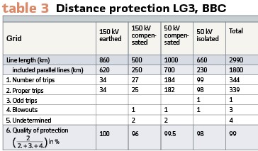
Table 3 shows the Behavior of the distance protection LG3, BBC, in 4 different grids for one year.
For the undetermined cases it is not possible to distinguish clearly if the protection was working properly or not. The column “blowout” contains one case in the 150-kV-grid, when a DC fuse (4 A) blew when the relay started up. The reason was that the entire series of fuses did not work properly. This shows that the fuses are an important element. The 2 other cases have been caused by mechanical errors. In 73% of all cases the relays tripped in fast time, 27% at a later stage. In 6% of the cases backup relays tripped. This statistic shows clearly, that after the first installation of fast distance relays in the earthed 150kV-grid in the years 1942- 1945 it had no bad impact on the operation of the grid.
With the old protection 96% of all trips have been ok. Every 6 up to 12 months the relays have been tested again utilizing a test set. Comparing the solidly earthed and compensated grid or the isolated one it is obvious, that in the earthed grid every earth fault causes a trip.
Since the healthy phases have no increased voltage, there are no flashovers, especially at remote locations. So, the disturbance remains in one area only. The protection sees clear circumstances, this decreases the number of unclear faults.
The relay committee at CIGRE met in 1952. The report #332 proposed to protect the stator against faults between the phases and phase-to-earth. This was mainly to protect in case of overvoltage or damaged isolation. Differential protection shall be used for generators > 1 MVA und voltage < 5 kV. Also, smaller machines (0.5 MVA) and voltage > 5 kV shall be protected like this. Turbines > 50 MVA shall be protected with extremely fast differential protection. When generator’s neutral point is not connected directly to earth an additional stator earth fault protection shall be used.
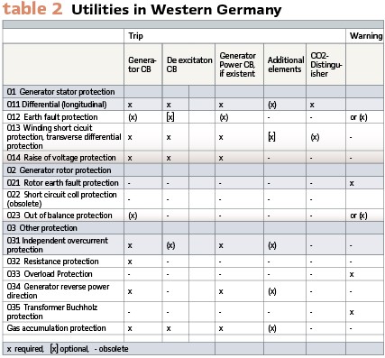
Back to Germany. The fast development of the relays was the trigger for the Western Germany organization of utilities (VDEW, Vereinigung Deutscher Elektrizitätswerke) to rework the “relay book” completely.
Figure 2 shows a later edition. It contained a glossary of terms as well as relay schemes to be used.
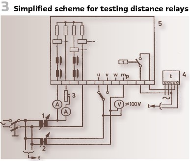
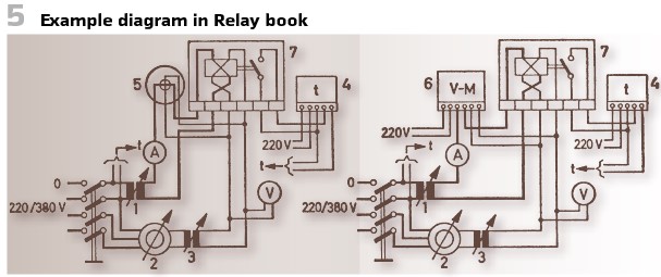
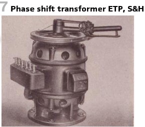
Figure 5 shows an example scheme for testing directional relays 7, It used a phase shift transformer 2, a wattmeter 5 and vector meter.
Heavy “phase rotating transformer” (35 kg) had been used. They could produce any phase shift of up to 180 degrees. They consisted of fixed stator and rotary current windings. The rotor could be used to setup a value. Fine tuning was possible with handwheel. A scale visualized the value.
They came with 6 connections plus, this allowed star and delta connection. The primary voltage possible was up to 500 V (interconnected). Figure 7 shows the device.
To test the characteristic of an impedance the most comfortable way is as shown in Figure 3.
This setup can be used for mixed impedance relays as well with phase shift 0 degrees. To measure with the test set is an advantage, distortions in the grid’s voltage do not change the ratio of voltage and current. The setup of different fault scenarios can be done via switch 5.
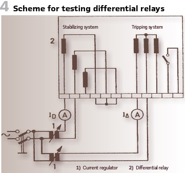
When testing differential relays (Figure 4) the most important are the characteristics. How to check such a characteristic show in the picture. It requires 3 phase current switches.
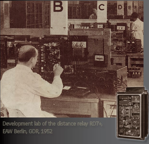
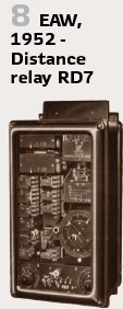
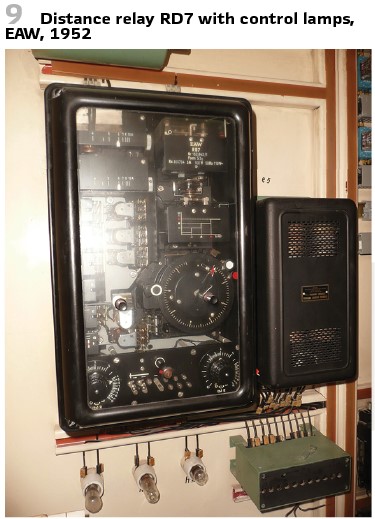
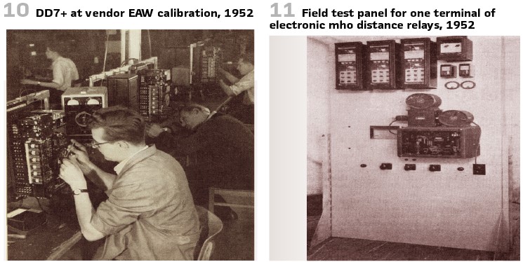
The one and only relay vendor in the GDR was EAW. Their distance relay RD7 was released in 1952 (Figure 8). Later a RD7+ came out, with integrated test switch. When this switch was pressed, an auxiliary relay arranged the startup of the relay, at the end time the relay tripped.
At the same time the tripping circuit was interrupted, and only after the pressing and the release of the relay it was established again. The glow lamp supervises the measurement voltage. Additionally, the test plug is available (Figure 9). Figure 10 shows the calibration of the relay RD7+ at the vendor.
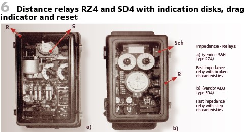
To support the engineers in the substations, O. v. Wirén at BEWAG Berlin published a handy book in 1950. It explains briefly the operational principle of the relays used, explained the indicating disks and how to reset. After every disturbance in the grid all the indications have been collected and the proper operation of the relays was checked.
- Sch Indication
- R Reset
- S Drag indicator
Figure 6 shows distance relays RZ4 and SD4.
The testing period at BEWAG was as follows:
- Every relay in the power stations and substations: 1 year.
- Relays in small stations: 1.5 years
- Relays in grid stations: 2 years
- Relays in customer’s substations: 2 years
At the routine testing the most important was to measure the first time, before the relay was operated manually or electrically. This showed how the relay would operate in case of a disturbance. All the routine tests have been performed as primary tests. This allowed a check of wirings, measurement transformers and relays together. If the relay’s characteristic is no longer as specified, there was a huge revision at the lab necessary. It was very important to check the contacts, search for rusting, corrosion and dust.
The Austrian magazine for the power industry (ÖZE) published a paper of an engineer, who was with Verbundgesellschaft Vienna. All the relays (earth fault, differential, line) were mounted by the suppliers and retested afterwards. Once in a year this had to be repeated.
This was not valid for simpler relays as overcurrent and overvoltage devices. They have been mounted and set up without additional test. But especially those devices have been mounted for instance in dirty environments. That’s why the author recommended, to check them more often.
To keep it simple, especially secondary relays with nominal current of 1 A or 5 A should be tested utilizing a rheostat connected to 220 V auxiliary voltage.
Since the current values have been between 5 up to 10 A, the power consumption was as 1 KW and 2 KW. Also, voltage relays could be tested with a rheostat. Connected to the 220 V AC grid it was used as a voltage divider. 450 Ω, 120 W was sufficient for this purpose. It was very important to measure the reset value. The contacts should be open, when the time set was achieved. Here the Austrian author reported huge problems, the ratio was sometimes 0.6 only. As a general rule the value should be at least 0.8. Special mechanical adjustments allowed to improve it. Nevertheless, he recommended to push the vendors to take care of this, to avoid adjustments and efforts on site.
For all that we described so far, we moved in the German speaking countries. When we move to the US and talk about distance protection, we talk about Mho relays. The characteristics of very high speed and low burden make the application of electronic relays desirable in places where conventional electromagnetic relays are not adequate. An electronic distance relay with a mho-type characteristic was described in 1948. Its development was undertaken to determine the suitability of electronic principles and electron tubes for application to protective relays.
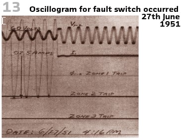
Although extensive laboratory testing indicated that the operating principles employed in this relay were quite satisfactory, it was felt that unknown disturbances which cannot be simulated in the laboratory might adversely affect relay operation. Accordingly, a field test program was arranged and published at AIEE by H. MACPHERSON in 1953.
It was closely studying the effect of possible unknown disturbances on the electronic relaying principles used; and determining the’ reliability of electron tubes when they are used for high-speed distance relaying purposes. Since the occurrence of faults on a normal transmission line is relatively infrequent, it was desirable to select a line with a high fault incidence rate.
The 50 mile 88 KV line between the Appalachian Electric Power Company’s Coalwood and Fremont substations appeared ideal since records indicated that faults occurred at the rate of over 20 per year. The line was constructed on steel towers and traverses a mountainous terrain.
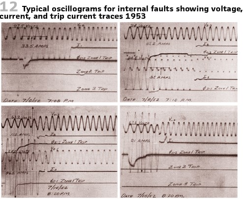
Description and Operating Characteristics of Mho-Type Electronic Distance Relay The sample electronic distance relays used for this field test program are functionally of the conventional 3-step mho type. The operating principle employed is one of comparing the instantaneous values of line voltage and line current at the maximum value of the line voltage during the voltage cycle (Figure 11, Figure 12, Figure 13).
On the test of frequency relays for load shedding Fountain and Blackburn (Westinghouse) published a paper at AIEE in 1955. The reduction of system frequency resulting from sudden overloads beyond generating capacity was an important subject to utility and industrial power system engineers and one on which there was little published information at this time. System planning attempted to guide the design of a system so that there was always sufficient available generation in a given area to match the expected loads.
However, there was always the possibility of a disturbance that may cause a deficiency in generating capacity for the existing load conditions. This situation could precipitate a major system outage unless it is quickly recognized, and the necessary remedial steps taken promptly.
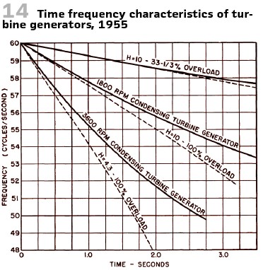
It became a problem for an operator to detect the condition at a time when his attention was fully occupied by the disturbance. Thus, automatic assistance or backup could prove invaluable. So, the application of frequency relays for load shedding was the idea. With a deficiency of generation causing the system frequency to decrease, the application of underfrequency relays can be used to disconnect automatically definite blocks of load or sectionalize the transmission system after the frequency drops below a predetermined value (Figure 14). Figure 15 shows the test setup.
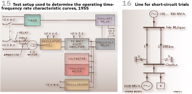
BBC reported in 1953 on earth short circuit trials at Shawinigan Water & Power Co., Montreal, Canada. The utility also performed short circuit trials at this time. It was on long 230-kV-line with high operational currents. The line was equipped with high-speed reclosers. Neutral point was solidly grounded. (Figure 16).
This series will be continued in the next edition.
info@walter-schossig.de www.walter-schossig.de
thomas.schossig@omicronenergy.com
Biographies:
Walter Schossig (VDE) was born in Arnsdorf (now Czech Republic) in 1941. He studied electrical engineering in Zittau (Germany) and joined a utility in the former Eastern Germany. After the German reunion the utility was renamed as TEAG, Thueringer Energie AG in Erfurt. There he received his master’s degree and worked as a protection engineer until his retirement. He was a member of many study groups and associations. He is an active member of the working group “Medium Voltage Relaying” at the German VDE. He is the author of several papers, guidelines and the book “Netzschutztechnik [Power System Protection].” He works on a chronicle about the history of electricity supply, with emphasis on protection and control.
Thomas Schossig (IEEE) received his master’s degree in Electrical Engineering at the Technical University of Ilmenau (Germany) in 1998. He worked as a project engineer for control systems and as a team leader for protective relaying at VA TECH SAT in Germany from 1998 until 2005.
In 2006 he joined OMICRON as a product manager for substation communication products. He is author of several papers and a member of standardization WGs.