by Walter Schossig, Germany, and Thomas Schossig, OMICRON electronics GmbH, Austria
In the last issue we covered interesting stories on the testing in the 1960s. Let’s continue our journey in the US again. The tests on transistorized phase comparison relaying by Horowitz, McConnell and Seeley started already in 1959. The relays of type SLD, CEYB and CEY by GE have been in the 138-kV grid of AEP in the US.
The goal was to clear three-phase faults and ground faults properly. The 23-mile line between the Philo and Muskingum River plants was chosen to serve as the test line for the following reasons:
Ample fault current is available- a line to-ground fault at Muskingum would result in approximately 20000 A to the fault
The test line is one pair of 138 kV circuits between these two plants, so load flow and system ties would not be interrupted during the tests
Recent changes at Muskingum resulted in the availability of a spare oil circuit breaker at the time of the tests. This breaker plus the 2-bus-scheme which exits there made the switching of faults relatively simple
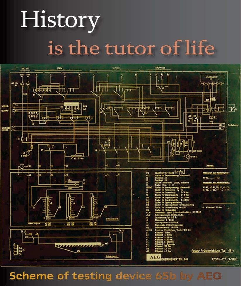
Figure 1 shows the faults structure for the field tests at AEP.
The relays originally installed on the test line consisted of directional-comparison carrier-current relays which were replaced by the SLD relay and a single CEYB relay. Three 3-zone distance relays and time-delay and instantaneous directional-overcurrent ground relay, originally installed for backup protection were retained, but with the phase relay first zone and ground relay instantaneous element delayed 4 cycles to give the test relay full opportunity to operate but still insure fast breaking. The spare breaker was used to close into the fault and had existing carrier current and backup distance relays. Faults were made internal or external by use of by-pass and bus disconnect switches on the two busses existing at Muskingum.
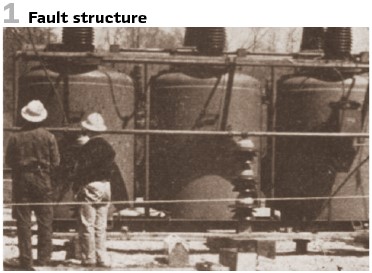
12 different fault types could be tested, containing internal and external faults. To record fully the currents, voltages and relay operations, each terminal had a 4-gun cathode-ray oscilloscope (cro) with a strip-camera attached, magnetic oscillographs with 13 elements at Muskingum and 9 elements at Philo, and the necessary pulse generators and electronic switches to accomplish the proper coordination. Synchronizing of the recording apparatus at the two terminals was accomplished by use of the carrier current channel, and an auxiliary relay sealed in through its own contacts and the receiver alarm relay contacts at each terminal, to initiate the timing upon interruption of the carrier. The SLD relays used for the test were modified to provide amplifiers required for recording operational values within the relay itself. In addition, an emergency AC supply normally available for emergency communication power was cut in prior to each test to provide a constant AC supply for the cro recording apparatus regardless of the station voltage during the tests. Figure 2 shows an oscillogram, made for an internal fault between phase 2 and 3.
Traces 4,6 show the fault breaker current (phase 2,3); traces 9-12 show the line breaker current, residual and all phases. Trace 13 visualizes the backup trip current and trace 15 the transmitter drive (down= on).
The performance of the new relays was excellent, and no design changes of its basic circuits were required. Study of the test results suggested changes in application practices and relay settings to cover more severe fault conditions. The Protective Relays Application Guide is known also today. The 1967 edition was published by The English Electric Company Limited in Stafford. The book contained the cumulated experience and techniques by practicing engineers for the solution of relaying problems in power systems. One chapter covers testing and commissioning. Already in 1967, the engineers have been confronted with the complexity of protective schemes and relays and adapted the testing technology accordingly. Also, at this time protective gear testing was divided into the three stages factory tests, initial commissioning tests and periodic maintenance tests.
It was always the responsibility of the relay manufacturer to provide adequate and efficient testing of all protective gear before it was accepted and commissioned. For a protection scheme or relay to be tested adequately, the operational conditions must be faithfully reproduced. Unfortunately, this was impractical in a single test equipment, therefore separate light and heavy current tests were carried out and the results correlated. Light current tests were carried out on the relays alone, using special test benches for individual relays and an artificial transmission line for testing several relays in a scheme. Heavy current tests were carried out with the relays and current transformers connected operationally.
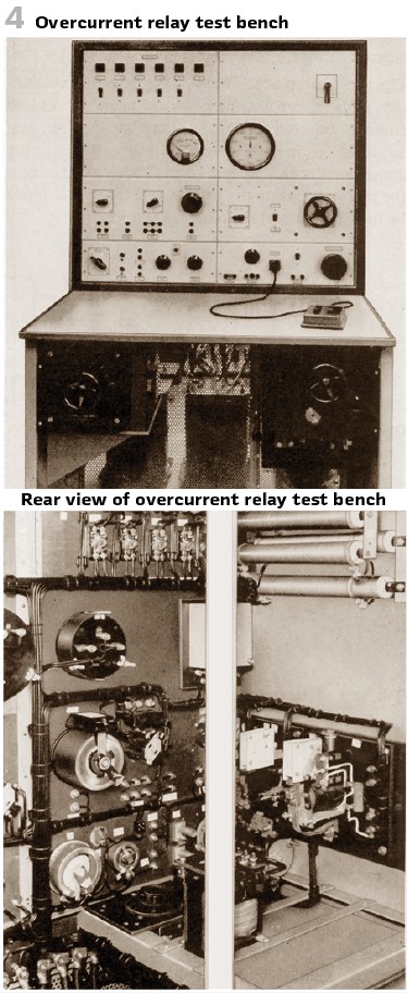
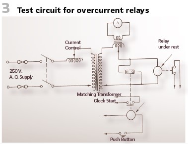
Figure 4 shows an example of a test bench. This test bench was used for checking the characteristics of invers, very inverse and extremely inverse definite minimum time overcurrent relays and also the directional discrimination of directional inverse time overcurrent relays. By the addition of portable test boxes this bench could be adapted for measuring overshoot, and also for testing other relays as percentage differential and inverse time voltage.
The basic circuit for testing is shown in Figure 3. The harmonic content in the current waveform was kept to within 2% of the fundamental by adjusting the current through a choke which has an impedance of at least six times as of the relay under test. Interchangeable matching transformers were used for differently rated relays, so that the same burden was imposed on the control circuit for all current ratings. The test current was adjusted to the desired level with the relay short circuited by a normally closed contact on the starting contactor. The test sequence was initiated by energizing the starting contactor, which releases the short circuit across the relay and starts the timer. The timer was stopped by the operation of the relay under test.
The method adopted for load adjustment allows sufficient time for the current to be accurately set without overloading the relay, and also gives a steady ammeter reading immediately on transference of the current of the relay since the pointer does not have to rise from zero. The timing device was either a synchronous motor driven clock or an electronic timer using counting tubes. The latter uses a high-frequency signal (1000 c/s) and a record from one millisecond to ten seconds. A precision ammeter with a maximum error of 0.5% of the reading was used for the current measurement.
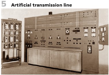
Figure 5 shows the artificial transmission line. It provided variable current and/or voltage at the relaying point with control of circuit time constant, duration of fault, point-on-wave at which the fault was applied. And the type of fault. This allowed static and dynamic testing over a wide range of simulated steady state and transient power system conditions. It was basically a three-phase circuit containing impedances representing source generation levels, transmission line constants, load impedances, fault impedances and earth impedances. All there were independently variable so that the fault MVA linked with the system voltage level, length of line to fault, system Z0/Z1 ratio, source, line, and system X/R rations etc. could be completely specified for the particular problem under investigation. The artificial transmission line was supplied from 660 Volt three phase 50 c/s mains with alternative arrangements for taking the supply from a variable frequency machine. The machine could also be connected to the load end of the line, so giving facilities for double end feed testing. Maximum fault current was 120 A, primary, but since this only passed for a short time, the equipment had a continuous rating of 30 A. All types of faults could be accommodated by suitable switching of contactors and fault could be applied in one of the positions: internal, external or on the parallel line. The application of the fault was controlled by means of a point-on-wave switch, so giving all degrees of offset. Resistance could be inserted in the fault paths (4 Ohms maximum, steps of 0.1 Ohm) to simulate arc resistance. Relay operation was timed by means of an electronic counter, calibrated in milliseconds, which was built into the control panel.
The types of protection which could be tested on this equipment was:
- High speed pilot wire
- Generator and transformer differential
- Instantaneous current relays
- Distance impedance
- Distance directional comparison
- Phase comparison
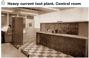
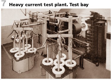
For the maximum current of 50000 A heavy current test plants were used. Figure 6 and Figure 7 show the “English Electric” test plant, comprised a 7.5 MVA 6,6 kV alternator, driven by a 1200 HP DC motor feeding heavy current test tables via the three single phase 3700 V/ 40 V transformers.
Looking into the details of the initial commissioning tests normally carried out we see:
- Checking the wiring diagrams
- Make a general inspection, checking all connections
- Measure the insulation resistance of all circuits
- Test the main CT for ratio and polarity
- Test main VR for ratio, polarity, and phasing
- Inspect and test the relays by secondary injection (see below)
Check the equipment by primary injection to prove the stability for external faults and to determine the effective current setting for internal faults
Check the tripping and alarm circuits for the equipment.
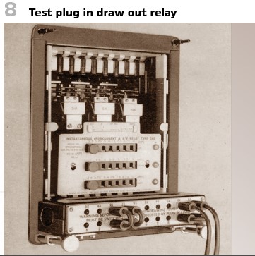
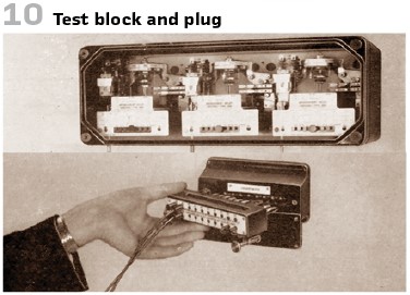
For the secondary injection it has been common practice to provide test blocks or test sockets in the relay circuits so that the connection can readily be made to test equipment without disturbing wiring (Figure 8, Figure 10).
Where several relays were used in a protection scheme, for example the distance protection scheme shown in Figure 14, test blocks common to the whole scheme are fitted on the relay panel and permit the scheme to be tested rather than just one relay at one time.
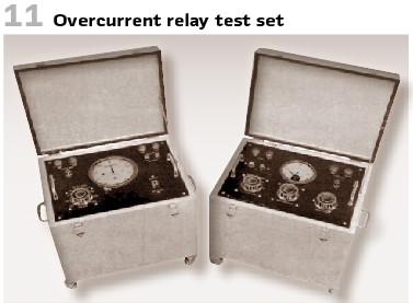
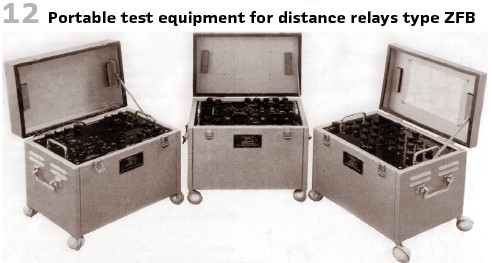
Typical portable test sets of this time can be seen in Figure 11 and Figure 12.
For the bigger generation units (≥ 100 MW) stationary test sets showed huge advantages.
Before this huge boards with control elements and elements to be plugged have been widely used but not recognized as easy to use. They only tested the measurement element, but not the tripping elements. Additionally, the relay was out of service during the test, the duration of the test depended on the experiences and knowledge level of the testing engineers. A huge improvement was the semi-automatic testing device RG 491 by the SIEMENS Schuckert-Werke in Western Germany. After the startup the test was performed automatically. The duration of a test was the operating time of the protection plus additional some 10 ms which was the operating time of the test set. The tripping connections were interrupted only once per channel. Additional interlockings blocked false trips and operation of circuit breakers. Also, the educational requirements were low because of the automated test. New developments in generator protection demanded developments in the testing devices as well. In the 1960s for the first-time electronic elements have become more relevant.
Before this only the generator or the deexciting breaker had to be operated. During the test only 2 channels for tripping had to be interrupted. At the huge units there was more: generator breaker, own power supply, turbine quick operation, tank breaker, switching breaker and more. At the electromechanical relays it was possible, to observe operation and repeat in case of problems.
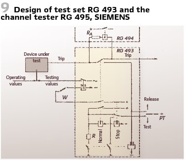
With the electronics everything was faster, but additional supervision was developed. Also, the tripping channels were tested and monitored. The switch W connects the device under test via the switch PT, the contacts and the stooping relay II and the startup relay I. The contact of relay II holds the relay and excites the relay IV. The tripping of the device under test is transferred via the auxiliary relay III. Relay II interrupts the testing values injected and stops the test. (Figure 9).
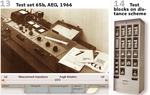
AEG’s testing device 65b consisted of 2 or 3 portable boxes. They could be opened. The boxes were made of steel. 6 cables connected the different boxes, in case of 3 boxes eight cables were used. All boxes came with handle and could be carried easily.
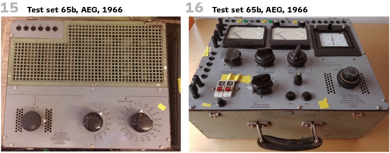
To setup the phase shift between current and voltage a rotating knob was used. To set it up as well as reading the measurement values was time consuming and could cause errors.
An additional angle rotating device makes the work easier There was no need to connect and supervise the measurement values additionally,
The space required for the test set was more than 2 meters. (Figures 13, 15, 16).
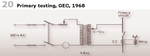
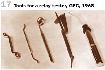
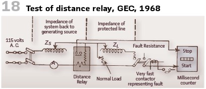
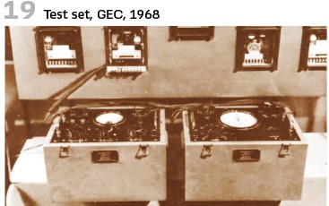
To learn more about GEC’s testing technology in the 1960’s Warringtos book on “Protection relays- their theory and practice” published in 1968 is of interest. We already mentioned it in the last issue. (Figures 17, 18, 19, 20).
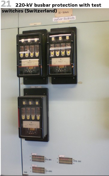
What was valid in the 1960s is valid today- testing busbar protection is a challenge.
The Aare-Tessin AG für Elektrizität in Switzerland used busbar protection in the 220 kV substation Mettlen with 20 feeders. The engineers could test with the test switch, if all parts of the differential protection work properly (Figure 21).
info@walter-schossig.de www.walter-schossig.de
thomas.schossig@omicronenergy.com
Biographies:

Walter Schossig (VDE) was born in Arnsdorf (now Czech Republic) in 1941. He studied electrical engineering in Zittau (Germany) and joined a utility in the former Eastern Germany. After the German reunion the utility was renamed as TEAG, Thueringer Energie AG in Erfurt. There he received his master’s degree and worked as a protection engineer until his retirement. He was a member of many study groups and associations. He is an active member of the working group “Medium Voltage Relaying” at the German VDE. He is the author of several papers, guidelines and the book “Netzschutztechnik
[Power System Protection]”. He works on a chronicle about the history of electricity supply, with emphasis on protection and control.
Thomas Schossig (IEEE) received his master’s degree in Electrical Engineering at the Technical University of Ilmenau (Germany) in 1998. He worked as a project engineer for control systems and as a team leader for protective relaying at VA TECH SAT in Germany from 1998 until 2005.
In 2006 he joined OMICRON as a product manager for substation communication products. He is author of several papers and a member of standardization WGs.