by Walter Schossig, Germany, and Thomas Schossig, OMICRON electronics GmbH, Austria
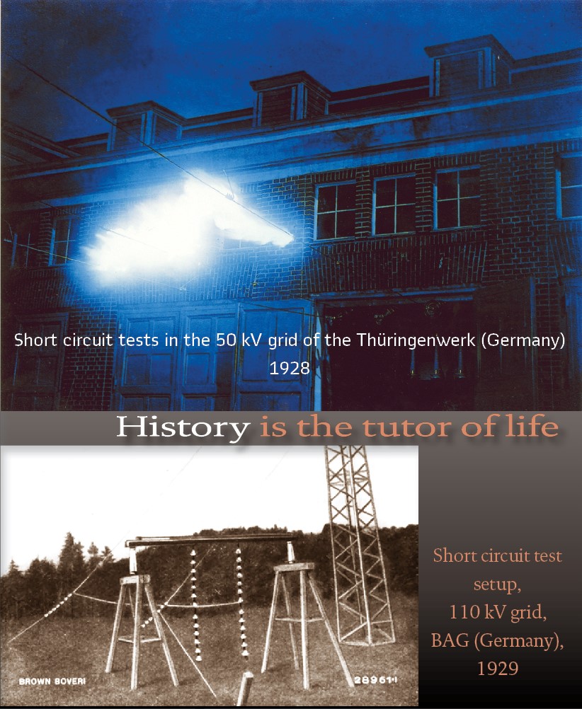
In the last issue we described secondary testing of relays utilizing test circuits and first test sets to produce primary values. Additionally, it was common practice to work with network models or even testing inside the primary grid. This was mainly used for earth fault and short circuit tests. Very important experiences could be collected in the high voltage, as well as the medium voltage systems. This article describes the equipment used and tests performed.
Already in 1915, the NATURE MAGAZINE published a short paper, “The Principle of Similitude.” The author, Nobel-Prize-winning physicist John Strutt, Lord Rayleigh, introduced his paper by stating, “I have often been impressed by the scanty attention paid even by original workers in physics to the great principle of similitude”. He went on the propose many examples of physical behavior that could be easily predicted through an existing understanding of similar physical phenomena. So, we start with the early years of simulation, the analog simulation. As early as 1929, engineers were building analog-equivalent models to represent their power networks. The first aid to the application of power system stability analysis was the analog network analyzer, in which transmission lines were modeled as simple inductances and their capacitive properties sometimes neglected. Generators were often simply represented as a phase and magnitude adjustable voltage behind an inductor representing the generator’s impedance and the impedance of its unit transformer.
Already before this, in 1915 and 1916, first network models have been used in the US. The grids have been small, the voltage level was low – so the impact of capacity and line’s resistance versus the inductance could be neglected. It was sufficient to model the reactance with resistances and to operate with DC voltage. To perform such tests also for bigger grids and long lines, AC models have been needed representing capacitances, as well as active resistance. To check even grid stability, the development of such AC models started in the US in 1917. The first model was 3-phase without rotating generators. So, it was a static model. Unbalances could be modeled already but the infeed was not flexible. G.E.C came with such models (200…600 kVA), operated with 2300 V for lab application. In 1922 this company introduced the first model with rotating generators (3.75 kVA) operated with 10 A at 440 V.
At the Leipzig Fair 1924 the German AEG presented on a network model the application of selective overcurrent protection with distance protection. They could show selectivity in mashed grid configurations- independent of generator infeed and switching conditions. The excellent reliability of the relay (Figure 1) could be realized by the simple design. It consists of a single contact. This contact is the trip contact and is realized as indicating disk. This disk allows the operator to easily identify the feeder with trip.
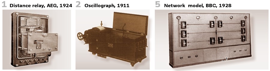
Also, the Swiss BBC showed their distance relay utilizing network model. This happened in 1928, at the annual general meeting of the Swiss SEV in Baden (Figure 5). The model contained 5 line-sections, protected by distance protection. Small switches replaced the oil circuit breakers and allowed flexible combinations. The line impedances have been divided into 3 parts, so short circuits could be simulated at the middle of the line as well as on both sides. Infeed could be simulated at the 3 “centers” available. The line switched on is indicated by lamps. Short circuit contacts could be inserted and so the proper operation of the relays was easy to demonstrate – even without additional words or explanations.
Oscillographs became another important tool. First devices have been in use already in the early 1910s. At the 28th Annual Convention of the American Institute of Electrical Engineers, A.I.E.E., (predecessor of IEEE) in Chicago in 1911 Facciolie presented a paper online-oscillations- illustrated by records (Figure 3). The device used was a huge one (Figure 2).
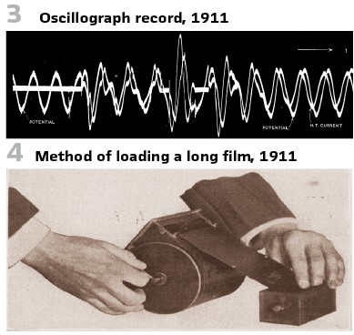
The storage media was film (Figure 4).
The protection guys found the application of oscilligrapghs quite useful. Legg presented a paper on the usage for recoding transmission line disturbances in 1928.
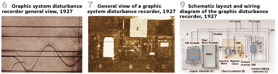
In the 15-element oseillograph, the records are all in the same time-phase relation. So, it was not an improvised oscillograph. Previous ones were in reality a combination of several oscillographs, with one tier above the other, so that the light beams crossed at the cylindrical lens and reached the film half in one height and half in another, and thus gave a different time relation on the film. All fifteen of the records are in exact time-phase relationship, and easily controlled (Figure 6).
The next step was a “High-Speed Graphic Voltmeter for Recording Magnitude and Duration of System Disturbances” as presented in 1927 (Figure 7). It consisted of a graphic voltmeter (A), the chart accelerator (B), a contact making voltmeter (C), and the necessary resistors (D and E).
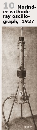
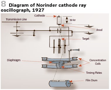
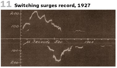
How it worked can be seen in Figure 9. The graphic voltmeter (A) runs, the salient-pole induction motor of the accelerator B runs continuously at synchronous speed; and the contact making voltmeter C being energized at the full voltage holds opens its contact V. As soon as a dip in voltage occurs, amounting to five per cent of normal or more, the contact-making voltmeter closes its contact and energizes the magnetic clutch of the chart-accelerator B.A “Norinder cathode ray oscillograph” was used in lightning investigations on transmission lines in 1928 (Figure 8, Figure 10), It was used to record switching surges on 132 kV line taken with rotating drum (Figure 11).
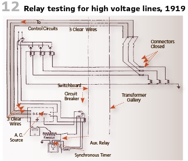
It was in 1917 at the 33rd meeting of the American Institute of Electrical Engineers (A.I.E.E) in Chicago when Philip Torchio, chief electrical engineer of New York Edison Co. presented the results of testing relays for high-voltage lines (Figure 12).
Transmission line relay protection was also a topic at the 35th annual convention of the A.I.E.E in Lake Placid in 1919. To achieve the best results with relays, it is required to test the relay completely in terms of times and current. Such tests shall be performed during the commissioning and every six months afterwards. They have been aware, that this testing is time consuming and have to be aligned with grid operation. So, they proposed to use test plans and defined intervals. The recommendation was to test the entire system, including the complete wiring and the relay itself.
The accuracy of testing was depending on the transformer used as well as the secondary load. Errors are possible because of the magnetizing currents at transformers and saturation.
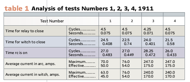
It might be interesting to see the times for the relays and switches to close. Table 1 shows the results of tests with arcing ground suppressors in the 40 kV grid of Southern Power Company (US).
Paul Ackerman of Shawinigan Water and Power Company, SW&P, (Canada), used in 1920/21 a combined voltage and current relay (balance beam principle). His main achievement on selective protection was to show staircase-shaped time grading for the first time. This he learned at short-circuit tests and in operation of the 50 kV grid at this time. Time relays with overcurrent startup protecting the machines could not start because of small short circuit currents. The impact of the arc-resistance was not recognized at this time. He only saw the short circuit current was sloping.
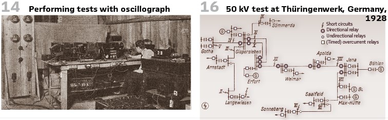
Also, the control of oil circuit breakers was tested with oscillographs. Figure 14 shows a setup in Baltimore.
The German company Preußische Kraftwerke Oberweser A.G. Kassel did a lot of short circuit tests in 1922 and have been completely equipped with V&H voltage drop relays. At the hydro power station Hemfuhrt at the dam “Edertalsperre” they built a 60 kV test line towards Hanover and equipped it with the relay. The voltage drop was depending on the apparent impedance which means the length of the line. Relays close to the fault location trip faster. They have been happy and used the relays in all substations. From the report: “Even if the tests have been “too clean” the results are very valuable. Malfunctions occurred and so we had to renew contacts and the oil circuit breakers of 6 different vendors, especially the magnetic contacts. Relays could stick and not disengage. We received reports from the substations once per week. The observed synchronous swing and compensating currents between the power stations. To avoid malfunctions of relays they increased the excitation current.”
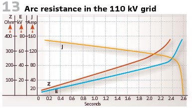
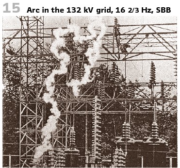
The impact of the arc resistance was not recognized as important at the beginning. The German Bayernwerk tested this in their high voltage grid (110 kV at this time) extensively and learned more about this. This also happened in Switzerland at time in the 50 kV grid. Here they recorded the currents in case of short circuits on post insulators utilizing oscillographs. The high resistances in high voltage systems have been caused by long lines and isolators. The arc resistance measured was 150 Ω at currents in the range of 50 and 100 A. Such currents are possible in case of short circuit and low load. Figure 13 shows the results of such an oscillography, the change of line impedance in case of short circuit, as well as the short circuit angle. The 132 kV grid of Swiss Railway (SBB) is solidly grounded. They tested short circuits on post insulators (length 1.2 m) with arc lengths of 10 meters. The resistance of the arc: 200 Ω (Figure 15). Distance protection was introduced successfully by Biermann- a huge achievement.
The existing protection systems, produced by Siemens & Halske worked very well at this time: polygonal protection, reverse time grading, etc. So, he received a lot of counterarguments when he presented the proposal at a conference. The approach was very new and so the utilities could be only convinced at practical tests. Short circuit tests as well as earth-fault tests have been performed. The first switchgear with AEG distance protection was in the 30 kV grid of Thüringische Elektrizitätslieferungsgesellschaft (ThElg) in Thuringia, Germany in the middle of the year 1924.
The owner of the 50kV grid in this county, the “Thüringenwerk“, decided to go for impedance protection as delivered by Siemens-Westinghouse in 1927. The power stations connected have been partly received the energy from this utility and operated own generators. So, in the power station Gispersleben they tested the relays together.
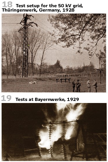
The protection relays have been in operation for more than one year without any problems and so they decided to go for additional tests in the spring of 1928. The trials have been covering the entire grid with 13 different points of failure. In May 1928 the new relays have been working on 22 different locations in the 50 kV grid and operated properly in case of 2-phase and 3-phase faults during tests (Figure 16, Figure 17, Figure 18).
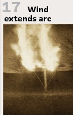
For metallic faults the results confirmed the calculations with deviations acceptable from practical point of view. The arc resistance of such arcs (with limited flame arc) was causing an additional delay of 0.5 s. The arc voltage was 10…12% of the nominal one. Since the basic time of the protection start was very low (0.25 s), this additional time was acceptable. All tests went well. But in case of a storm (Figure 17) the arc became very long. The impedance measured by the relay was below the operating impedance. Since the voltage decreases and the increase of current was rather small- the relay could not start. So, the arc was quenching after 4 seconds- a long time.
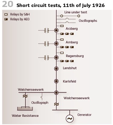
The requirements of the Bayernwerke on AEG and S&H resulted in the “double distance protection”. To verify lab results of vendors and to collect further experiences, the vendors have been invited to join the tests. This took place in July of 1926, and March and October 1927 (Figure 20).
The short circuit was in Arzberg substation. The generator was 330 km away -in Walchenseewerk.
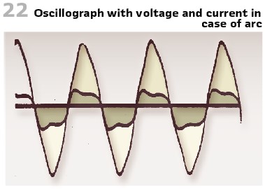
The goal was to check the behavior of the relays in case of small generation and big excitation (as during a weekend). Especially in this case the conditions have been challenging. The first challenge was to collect experiences on the arc. So, arcs have been initiated between two conductors with no load, half load and full load. A lot of oscillograph recordings were made. They estimated the investigations as worth to be continued, especially to learn more on the short circuit arc.
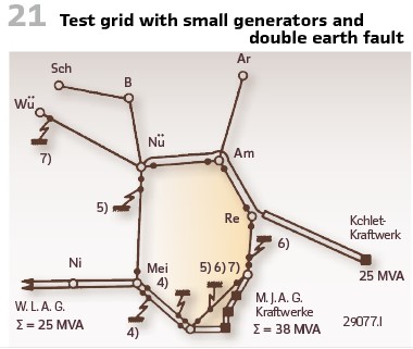
Figure 22 shows current and voltage when an arc occurred. The current shows sine curve, but the voltage curve shows clear distortion.
After those tests the vendors involved used the time to redesign the devices. So, in the spring of 1927 it was time to test the relays for the second time- under the same conditions. The progress made was obvious, especially in terms of startup current sensitivity and tripping time. The importance of short clearing time shows in Figure 13. The curve J, indicating the current, shows linear behavior at the beginning, but then drops down. This is because the arc is stalling. In case of stable arc, the curve continues and indicates the steady short-circuit current. Voltage curve E shows the opposite behavior: The arc resistance is proportional to time and drops down later. Before the unstable front is reached, the short circuit has to be switched off. This is the reason for demanding small clearing times (less than 3 s).
In the meantime, BBC also came with a new relay according to the needs of Bayernwerk. Same procedure for this vendor, they tried it out on the 16th of October 1927.
To use it in main ring (Figure 21) the following specs have been published:
- Test installation, to allow change in case of problems and the wish to switch back to another vendor
- The time for the change to new protection shall be reduced to the minimum
- All experiences made with other vendors shall be considered
To fulfill all these demands, the Bayernwerke took over mounting and commissioning. All relays have been mounted in a lab on wooden boards. Once mounted, everything was tested and could be moved in special boxes to the substation. In the substation this was mounted in such manner, that switching between old and new was easily possible. The connection to the measurement transformers was easy to change, the boards have been mounted so that they could be observed. Together with the three single pole distance relays, there was an earth fault relay mounted. Additionally, the auxiliary circuits have been supervised with lamps. A small changeover switch was between both protection systems. This should allow supervision and testing even for not so qualified people. To do so for every substation an own protection test system was bought. This was portable and could be moved among the different panels. It consisted of inductors and plugs. The switch disconnected the relay from the grid and connected it to the test set. The test set injected typical fault utilizing station battery. This allowed testing of relays and all contacts. The CTs have been supervised with Ampere meters. Additionally, the oil circuit breaker trips have been checked.
Depending on the operational conditions it should be possible to have “artificial” faults (short circuit as well as double earth faults) to check the relay’s proper trip. To do so, they established test program with BBC in March of 1929. It was essential to guarantee selective protection even in case of special conditions. This was especially important in case of small, as well as strong generation. The tests have been performed with small load as well as peak times. So, they performed some of the tests during the night.
The content of tests was always:
- Test of the relays with 2 and 3-phase faults
- Test of the relays with double earth faults
For the double earth faults, it was the demand of the customer, to apply only one fault in this case. BBC developed a scheme to realize this, nevertheless this was never tested before. Since such faults happened often, it was important to test it. This was done with huge efforts. They performed 5 double earth faults.
Additionally, “swing tests” have been demanded.
This was realized with 2-phase short circuit at the bushings of the line Meilingen-Karlsfeld at Meilingen substation. One earth fault was made at line 1 in Karlsfeld, the second at line 2 in Meitingen. After the first earth fault and during the 10th test in Karlsfeld the oil circuit breaker of line 2 in showed an earth fault as well and was damaged. The power stations started to swing, additionally breaker in Amberg towards Regensburg tripped (Figure 19).
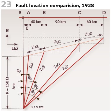
The tests brought additionally experiences. For instance the 110 kV short circuit trials at the same utility in 1928 showed, that the arc resistance was up to 150 Ω at currents in the range between 50 and 100 A. Calculations showed that in case of 2-phase arc faults the fault location was shown at 150 km – even if the fault was only 10 km away (Figure 23).
Lesson learned: The conditions in the medium voltage grid are not better han in the high voltage. This was especially valid in case of short lines.
In those years a lot of tests have been performed. So, we will have a follow-up article on this.
walter.schossig@pacw.org www.walter-schossig.de
thomas.schossig@omicronenergy.com
Biographies:

Walter Schossig (VDE) was born in Arnsdorf (now Czech Republic) in 1941. He studied electrical engineering in Zittau (Germany), and joined a utility in the former Eastern Germany. After the German reunion the utility was renamed as TEAG, Thueringer Energie AG in Erfurt. There he received his master’s degree and worked as a protection engineer until his retirement. He was a member of many study groups and associations. He is an active member of the working group “Medium Voltage Relaying” at the German VDE. He is the author of several papers, guidelines and the book “Netzschutztechnik [Power System Protection].” He works on a chronicle about the history of electricity supply, with emphasis on protection and control.

Thomas Schossig (IEEE) received his master’s degree in Electrical Engineering at the Technical University of Ilmenau (Germany) in 1998. He worked as a project engineer for control systems and as a team leader for protective relaying at VA TECH SAT in Germany from 1998 until 2005.
In 2006 he joined OMICRON as a product manager for substation communication products. He is author of several papers and a member of standardization WGs.