by Walter Schossig, Germany, and Thomas Schossig, OMICRON electronics GmbH, Austria
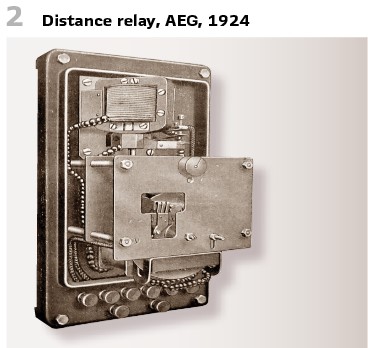
In the last issue we showed the first tests performed in the 1920s. This was the time, when distance protection started the success story. Figure 2 shows AEG’s (Germany) distance protection relay (1924).
Already in 1923 AEG and Dr. Paul Meyer could approve the viability of the distance protection principle. Also, in the US Chrichton published his paper “The Distance Relay for automatically Sectionalizing Electrical Net Works” in the Transactions of AIEE in 1923.
It was in 1924 when the first AEG distance relays (called “Biermanns-Relays” at this time) have been put into operation. This happened in the 30 kV overhead line grid of the German utility ThELG in Thuringia. We assume that it was substation Schmalkalden 1. They also immediately started with on-site trials and short circuit experiments.
It was also during the 1920s (1924, 1925, und 1925) when Max Buchholz started extensively testing with his “Buchholz relay.” It was developed and built by himself. The device could be used for faults inside and outside transformers, as well as oil circuit breakers.
It was on the 23rd of October 1927 when he started his tests at Hermfurth power station. Some facts:
- Utility „Preußischen Kraftwerke Oberweser A.G. “(Germany)
- 5 generators with 15000 kVA total
- 60-kV-double line Hemfurth-Borken, 2x3x50 mm2 Cu
- Test setups at power station Borken with 60 and 5 kV via 12500 kVA AEG transformer
- Load have been water resistances (5 kV, in the Schwalm river)
- Trials on a 1000 kVA transformer, type O.D.Ha., 1105/140, 1000 kVA, connection A2 which is today Yy0, 60/5 kV, 9,55/109 A, AEG, with aluminum winding (T)
- In addition, and for comparison purposes differential protection S&H was connected
The test BI/2 (Figure 1) is in the case that an arc is occurring because of bad contact, for instance on solder joints, screws or on a broken line. One phase is broken between core and feedthrough (a). An isolated rope imitated the arc.
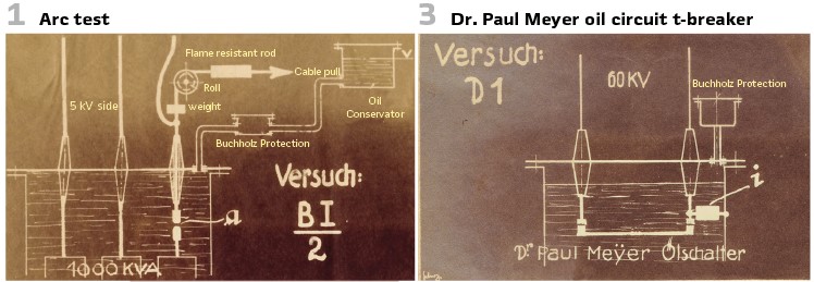
The test D1 (Figure 3) shows 60 kV oil circuit breaker with the new protection. In one chamber a leakage path with an isolator is established between chamber and phase.
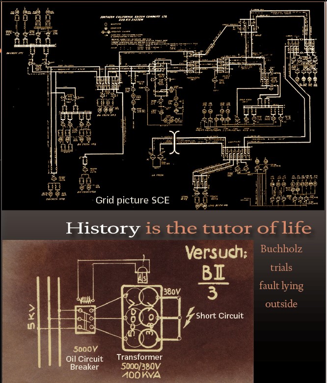
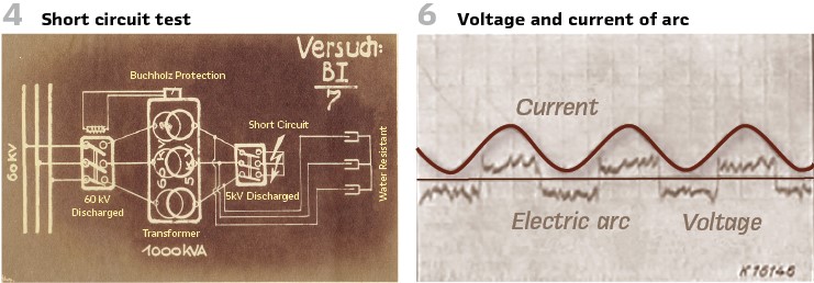
The test BI7 (Figure 4) was short circuit on the low voltage side. A 5 kV circuit breaker is short circuited on all three phases remotely. The load is again water resistance connected to transformer (right hand side).
The transformer mentioned was already used for tests in 1924. In the Sandershausen substation, close to Cassel (Germany, today Kassel) it was operated by the Preußischen Kraftwerke Oberweser A.G. They organized presentation for huge audience with comparison trials utilizing differential protection and the new Buchholz protection systems. The setup is shown in Figure 5. The load is on the low voltage side. Again, the water resistance W was cooled permanently by fresh water. The cable pull S moved the phases. AEG built in the normal and sensitive differential protection for supervision. The protection systems consisted of:
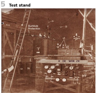
- 2x CTs on the 60 kV side st
- 2x CTs on the 5 kV side st
- 1x three-pole differential relay DR
- 1x Dropping resistor w
- 1x Wattmeter differential relay WDR
- 1x Dropping resistor w
- 1x auxiliary relay ZR
- 1x auxiliary transformer HT, same number of taps as main transformer
The setup on title page shows the built-in faults within the transformer.
Now the comparison could start. The Buchholz relay (B) was built on the line V between the transformer (T) and the expansion vessel (AG).
Both protection systems worked in parallel. To check operation of both systems independently, they did not trip the circuit breaker but only different lamps. L1 showed the alarm, L2 the trip of the Buchholz relay. L3 was connected to the normal differential protection, L4 to the sensitive one. A recording device R recorded on paper- 30 millimeters per second. The trip started manually via button.
The tests showed the superiority of the Buchholz relay especially to the conventional current comparison principle. Even in case of small disturbances or just starting ones they are indicated properly, and it trips immediately in case of serious danger for the transformer. As shown in trials:
- Buchholz relay alarms at the beginning of fault
- Immediately trips in case of hazard
- Alarms in case of unallowed sinking of oil level and switching off in case of danger
- Collects all exhausting gasses
In 1925 next trials took place in AEG’s transformer production company in Berlin-Oberschöneweide. The protected asset was a 1000 kVA transformer 60/5 kV. The main objective was to show, that also in case of faults outside the protection zone the protection works selectively. From the testing report:
“Two tests have been performed, one at voltage level of 6250 volts, another one with 7000 volts. The 15000 kVA generator was excited with full voltage. Then the generator was connected remotely to the short circuit transformer. The amperemeter showed 1400 A. The transformer received powerful push; the generator’s revolution speed decreased significantly. As wished, the Buchholz protection did not trip.
In 1925 the Bayernwerke in Germany reported several interesting field trials. Together with the vendor S & H. arc trials in the 100 kV grid took place. Oscillography recordings were made. In the high voltage grid earth fault trials took place. After this the tripping of the line with earth fault was rejected. During the years after extensive trials in the 110 kV grid testing the impact of arc with the AEG distance protection have been reported. Also, short circuit trials with AEG and S & H have been performed.
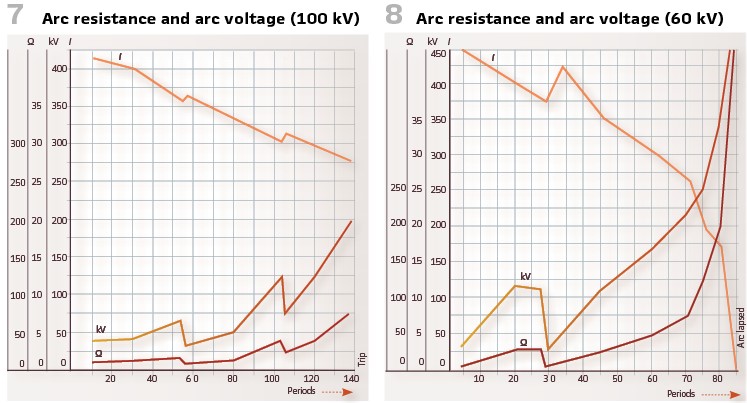
Dr. Paul Meyer AG tested the N-relays in the 15 kV grid of Grone und Gumbinnen, and the 5 kV grid of Essen (Germany). Dr. Michael M. Walter of AEG made trials in the 70 kV grid. Between 1925 and 1927 the behavior of impedance protection in case of two- and three phase short circuits was tested in 70 tests. The result was that the arc resistance in the 40 kV grid with transmission lines could be neglected for measuring the apparent impedance in short circuit loop with impedance relays. This could be explained, because the short circuit currents have been big due to the large grids, but the interspace between the conductors was rather small. The practical experience and other trials confirmed this. Josef Biermanns, AEG, published the result of trials in 1926. For instance, he recorded the voltage and the current of the AC arc (Figure 6).
The rectangular form can be explained with the decreasing arc resistance during increasing current. So, the voltage stays constant after ignition of the arc during the half period. The current follows sine curve. Experiments of General Electric showed distortions of the voltage far away from the source, but distortions of the currents near the source. This can be also explained with the impact of the ratio of arc resistance on the impedance. Arc-backs have an impact on both curves as well. The magnitude of arc resistance depends on the short circuit current, the electrodes, arc length and combustion period.
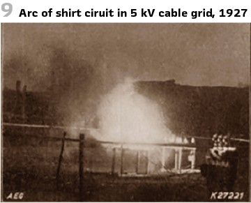
Figure7 shows the arc resistance and the arc voltage in different grids.
The test has been performed at Preußenelektra in Kassel in 1929. During the tests they tried to emulate the real conditions for the arc between the towers in case of crossing one over the other. This should allow the ascending air to influence the arc resistance. The phase distance in the 100kV was 2.4 meters, even if in field the value was between 3.3 and 3.5 meters. So, the arc resistance measured was smaller. The same for the 60 kV grid, here the distance was decreased to 1.75…2.5 meters. It was very stormy, so with the starting value of 300 A or 500 A the arc could be established for 1 up to 1.5 seconds only. During the first periods the value of 20 Ohms could be reached seldomly. During the periods between 50 and 60 the resistance increased to 50…60 Ohms. Only just before going out, when the length of arc was between 8 meters and 15 meters, high resistances could be reached. The arc was released via thin copper cables, which was vaporizing immediately, In other 100 kV grids (Bayernwerk and Tiwag), when the line distance was normally 3 meters and above, the initial values of the arc resistance could be 50 Ohms, even in case of small currents (100 A).

The purpose of all this trials by Dr. Michael Walter of AEG was to detect the impact of the arc on the impedance protection. In 40 kV grids the arc resistance can be neglected for the impedance calculation. This was confirmed practically. With 70 experiments between 1925 and 1927 this could be tested with distance protection relays.
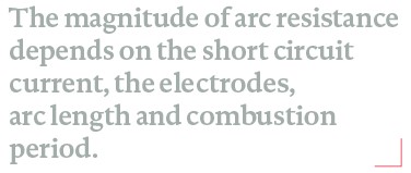
Figure 9 shows the example of a steel plant in Germany. The short circuit current was 2500 A, the distance between the electrodes approximately 4 cm, arc voltage 300 V. This was even recorded on a film at this time.
In the high voltage transmission grid this differs. The short circuit currents are smaller, the arc resistances can be bigger. It was observed that the arcs are stable for a certain time.
As mentioned, the impact of arc resistance becomes important if the grid’s voltage is above 40 kV. They learned that the impact was especially important under low load conditions during the night and on Sundays. In this case the operating time of the impedance relays increased dramatically. This is why new resistance depending relays have been introduced, only taking the inductive resistance into account. This could eliminate the arc, which was ohmic mainly. The relays have been called “reactance relays,” produced by BBC and SSW at this time. Also, AEG released such relays, eliminating the arc resistance.
In England in the high voltage grid instead of reactance relays conventional impedance relays have been used further, but in combination with balance-fast-impedance-relays (Vickers). The time gradings of the balance relay and the impedance relays have been superimposed, realizing step characteristic.
Also, the vendor SSW could achieve decreasing operation time of the relays when they implemented “rush contacts” to clear faults on 2/3 of line lengths within 0.3…0.5 s, the rest with a climbing characteristic.
The Canadian practice fulfilled the so called “Ackerman Balance Fast Relay” with step characteristic (Clansfield Electrical Works, Toronto). Vendors such as Westinghouse, GEC and Compagnie des Compteurs produced “fast reactance relays”.
Utilizing impedance relays in the high voltage grid (> 50 kV) required short clearing times in the range of 0.02 to 0.2 s. During this time the arc was not established well. Taking into the account the operation time of circuit breakers at this time (0.2…0.7 s) could require tripping on the second zone. In this case the relays have been measuring the impedance already within 0.1 s and waiting until the circuit breaker tripped. Another opportunity was to measure the reactive impedance of the short circuit loop only.
They also learned that the harmonics of the arc caused a reactance which could not be detected by the reactance relays at this time. In addition to the ohmic arc resistance additional fault resistances appeared: earth resistance in case of earth short circuits and double earth faults, and contact resistances.
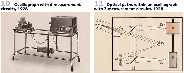
SIEMENS published a book on “electrical measurements” in 1928. On 474 pages all measurement principles known at this time have been collected. One chapter was even on oscillographs and recording devices. It describes “ink recorders” being even possible to record in different colors. They could also synchronize distributed recording. Oscillographs recorded on film reels at this time. Figure10 shows an example with six measurement circuits. This demanded huge efforts for the design of the optical elements used.
Figure 11 shows the optical paths within a device with 3 circuits. The condenser lens K, three light slits (S), the mirror R brought the light on the measurement loops M. Via the cylindrical lens (Z) the light was reflected on the photographic drum. An additional mirror K allowed live observation of the measurement with device P.
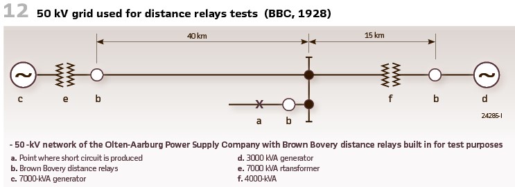
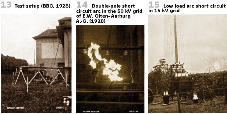
Around this time BBC was publishing the “Brown Boveri Review” magazine. In 1928 a paper “SELECTIVE PROTECTION OF TRANSMISSION LINES BY DISTANCE RELAYS“was published. They describe distance protection, time grading, impedance protection and its implementation in Brown Boveri’s distance relays. Joseph Stoecklin reported field trials. The requirements defined could be fulfilled. This covers for instance fault clearing times of maximum 2 seconds. Figures 12, 13 and 14 show the tests.
Also, SIEMENS published a paper by R. Bauch on “New developments on impedance and direction relays” in their magazine in 1929. In 1928 field tests took place in the 50 kV grid of the utility Thüringenwerk. 37 short circuits, double-phase and three- phase on different locations took places. Most of the tests happened during the weekends with lower load. The results have been satisfying, operating times between 0,35 s and 8 seconds with an average of 1.95 s, were measured. During the tests even a short circuit appeared and could confirm the proper operation of the new relays.
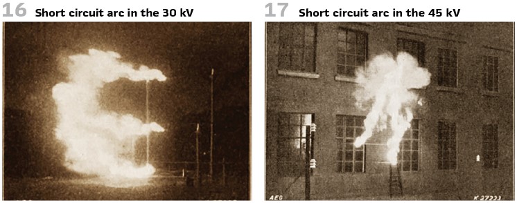
So, it was always important to test under different conditions. Figures 15, 16 and 17 show examples in different voltage levels.
Southern California Edition Company is a utility in the US. They published on the development of a relay protection system on the lines in 1930. The history of this presentation of the protective relays in the 220 kV transmission line, together with the results of application of protective relays was reported. Carrier current protection was discussed and used in a section of the 220 kV line. The title picture shows the single line diagram of the 220 kV. It is interesting to read the conclusions of the tests:
- In the interest of assuring a more reliable performance of the relays, duplicate sets of relays are installed
- The use of carrier current pilot protection on one section of the Vincent 220 kV transmission line has been satisfactory and has shown the value of this form of protection under conditions which would not permit the use of other forms of relays
- The use of current balanced relays and radial lines between the 220 kV major receiving stations and the 66 kV distribution stations has been an improvement
- The use of a remote alarm between unattended and attended stations to indicate when an oil circuit breaker trips out at the unattended stations has lessened the time of outage considerably in rural districts. Private telephone lines or carrier current equipment coupled to the transmission lines permits the installation of this remote alarm at a reasonable expenditure
With this outlook to SCADA and remote control we are finalizing the series in the tests and lessons learned in the 1920s.
info@walter-schossig.de www.walter-schossig.de
thomas.schossig@omicronenergy.com
Biographies:
Walter Schossig (VDE) was born in Arnsdorf (now Czech Republic) in 1941. He studied electrical engineering in Zittau (Germany), and joined a utility in the former Eastern Germany. After the German reunion the utility was renamed as TEAG, Thueringer Energie AG in Erfurt. There he received his master’s degree and worked as a protection engineer until his retirement. He was a member of many study groups and associations. He is an active member of the working group “Medium Voltage Relaying” at the German VDE. He is the author of several papers, guidelines and the book “Netzschutztechnik [Power System Protection].” He works on a chronicle about the history of electricity supply, with emphasis on protection and control.

Thomas Schossig (IEEE) received his master’s degree in Electrical Engineering at the Technical University of Ilmenau (Germany) in 1998. He worked as a project engineer for control systems and as a team leader for protective relaying at VA TECH SAT in Germany from 1998 until 2005.
In 2006 he joined OMICRON as a product manager for substation communication products. He is author of several papers and a member of standardization WGs.