by Ritwik Chowdhury and Normann Fischer, SEL Inc. USA
To better characterize the impact of limited negative sequence current (I2) injection from IBR’s on transmission line protection, The North American Electric Reliability Corporation (NERC) initiated a study which was led by Sandia National Laboratories.
There was collaboration from four IBR manufacturers (OEMs) who provided “real-code” black-box electromagnetic transient (EMT) models comprising a mix of Type 3 and 4 wind turbine generators (WTG), and photovoltaic (PV) Solar. These models represent actual firmware deployed in the field, wrapped in an appropriate wrapper for use in EMT programs, allowing creation of COMTRADE records. Two North American relay manufacturers then played back the COMTRADE records through their relays.
One aim of this study was to understand what deterministic and standardized behavior from IBRs would benefit protection system performance. Countries such as Germany and Australia have seen rapid penetration of IBRs and have already standardized the general requirements of injected currents from IBRs.
However, all standards recognize that the injected current from an IBR is controlled and cannot respond instantly, resulting in a timeframe (generally greater than one power-system cycle) where the response is not standardized. Conventionally deployed protective relays typically respond in this “one-cycle” timeframe.
Presently, in North America, there are no standardized performance requirements for IBR fault-current response when connecting to the transmission system, and a new standard would only define the behavior of new IBR installations.
Considering the delay in IBR response time and the present lack of standardization in most countries, we focus on providing insight into the line-protection challenges in systems with IBRs. We consider and characterize the behavioral differences between different types of IBRs. No two systems are identical but, using real-code models allowed us to keep the power system the same, while only substituting IBRs, and to characterize the similarities and differences in their response.
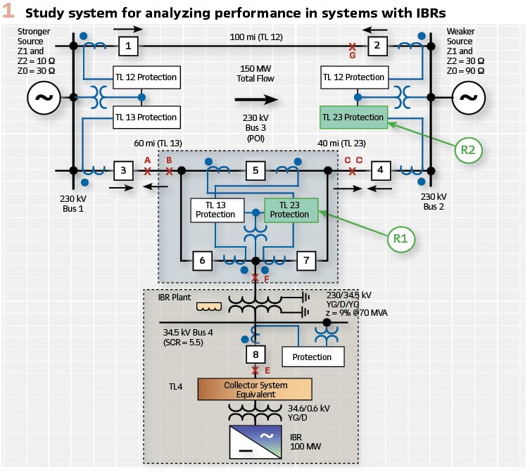
Study System
As part of the study performed by the team led by Sandia National Laboratories and later enhancements, 208 cases on the study system of Figure 1 were considered with the following mix:
- F our IBR OEMs:
- OEM1-Type 4 WTG
- OEM2-Type 4 WTG
- OEM3-Type 3 WTG
- OEM4-PV Solar

Type 4 WTG and PV solar consist of an energy harnessing component that interfaces with the grid via full power electronic converters. The response of a Type 4 WTG or PV solar to any disturbance of the power system is fully dependent on the power electronics converter.
Type 3 WTG on the other hand consist of two parallel paths to the grid: one directly connected to the stator of a rotating machine, and the other connected to the machine rotor via power electronic converter.
The r response of a Type 3 WTG to any system disturbance is a combination of the rotating machine response and the controls.
- Four fault types:
- AG
- ABG
- AB
- ABCG
- Two fault resistances (RF): 0 Ω and 5 Ω
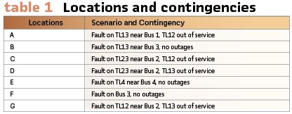
- Seven locations and contingencies, shown in Table I
Conventional Line-Protection Performance
Using the system described above, settings consistent with conventional line protection elements that consume full-cycle cosine filters data specific to one relay manufacturer were applied. Protection elements that employ other technologies, are beyond the scope of this article.
Protective Relay Elements
This section provides a simplified description (with several details omitted) of line-protection elements that are relevant for an application engineer to understand the message conveyed by the paper. The settings provided are relevant to protect lines with conventional sources.
Distance Element (21): For this article, to demonstrate the behavior of the apparent impedance, only the mho distance element is considered, as was done during the initial study. In microprocessor relays, the distance element consists of three phase loops (21AB, 21BC, 21CA) and three ground loops (21AG, 21BG, 21CG) that calculate the corresponding loop impedance (e.g., ZAB and ZAG).
A simplified version of the 21AB element is represented by Figure 3. The relay declares a fault in Zone 1 if:
- The calculated apparent loop impedance (ZAB) is less than the set reach (Z1MP)
- The loop current (IAB) is greater than the fault detector threshold (Z50P1)
- The directional element declares a forward fault (F32P), as explained further
- The fault-type identification and selection (FIDS) enables the fault loop, explained further
- No CVT transient detected (CVTBL)
The ground distance element (21AG) is similar (Figure 4).
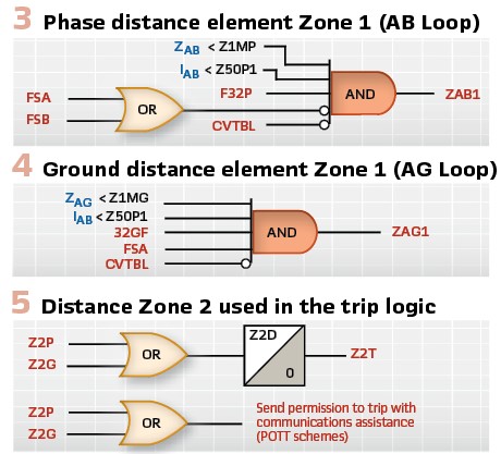
The security of the distance element is evaluated via use of the underreaching Zone 1 element, shown in Figure 3 and Figure 4. The reach for both Zone 1 phase and ground distance elements is set to 80 percent of the line impedance. The dependability of the distance element is evaluated via the overreaching Zone 2 element with a reach setting of 120 percent of the line impedance.
The logic for Zone 2 is similar to that of Zone 1, shown in Figure 3 and Figure 4, except there is no CVT-blocking logic. Zone 2 may be used as an input into a time-delayed (Z2D) backup or communications-aided tripping scheme, as shown in Figure 5. Z2D set to 20 cycles for this test series.
Directional Element (32): The 32Q element determines the directionality of unbalanced faults by calculating the negative sequence impedance (Z2), at the relaying point. Z2 is calculated by dividing the negative-sequence voltage (V2) by the negative sequence replica current (I2∠ Z2L) and then taking the real part, as shown (1).
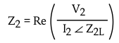
(1)
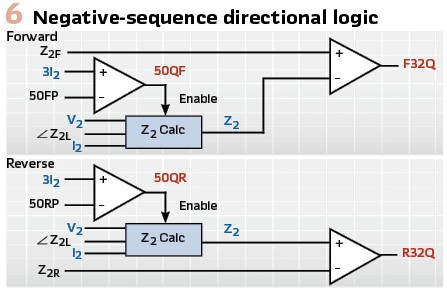
The Z2 calculation is only enabled when there is sufficient I2 as shown in Figure 6. An I2 overcurrent supervision is used with settable forward (50FP) and reverse pickup settings (50RP). For conventional systems, these values are often left as defaults, at 10 percent of the nominal CT secondary current for 50FP and 5 percent for 50RP.
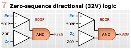
The ground distance elements detect line-to-ground (LG) faults and use either 32Q (Figure 6) or 32V (Figure 7). The operating principle for 32V is the same as 32Q; However, it uses zero-sequence voltage (V0) and zero sequence current (I0) to calculate the zero-sequence impedance (Z0) instead.
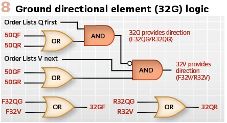
The 32Q element is immune to zero-sequence mutual coupling from a parallel line. For conventional ground relaying, the ground directional (32G) element gives priority to 32Q, as shown in Figure 8. However, if there is insufficient I2 but sufficient I0, then 32V is used to provide directionality.
Fault-Type Identification and Selection (FIDS): The phase distance element (21AB) can overreach for a resistive LG fault involving the A phase (AG) or B phase (BG), depending on load flow.
To prevent an overreach of the 21AB element, the relay must have a FIDS algorithm (Figure 9) that inhibits the 21AB element from operating if there is an AG or BG fault using the FSA and FSB digitals, as shown in Figure 3.
One method to identify the faulted loop is to compare the angle between I2 and I0.
A similar scenario exists for ground elements. The 21AG element can overreach for an LLG fault involving the A phase (ABG or CAG). To prevent overreach, the relay only permits the 21AG element to operate if the FSA digital from the FIDS logic is asserted, indicating either an AG or BCG fault.
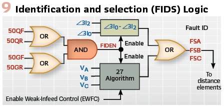
A simplified version of the FIDS logic is described in Figure 9. If sufficient I2 and I0 are present, the current based fault identification (FIDEN) logic is enabled and the angle between I2 and I0 is used to determine the fault type.
During weak infeed conditions, when the magnitude of I2 and I0are insufficient undervoltage elements can be used to aid fault-type identification.
Study Results
In the following subsections, we highlight reliability issues from the different IBR types. The issues only arise for faults when line TL13 is out-of-service (refer to Table I), when the IBR plant is radially connected to the power system.
Type 4 WTG: There were several misoperations with Type 4 WTG, several of these can be explained via the external ABG fault at Location G, shown in Figure 10 and explained as follows:
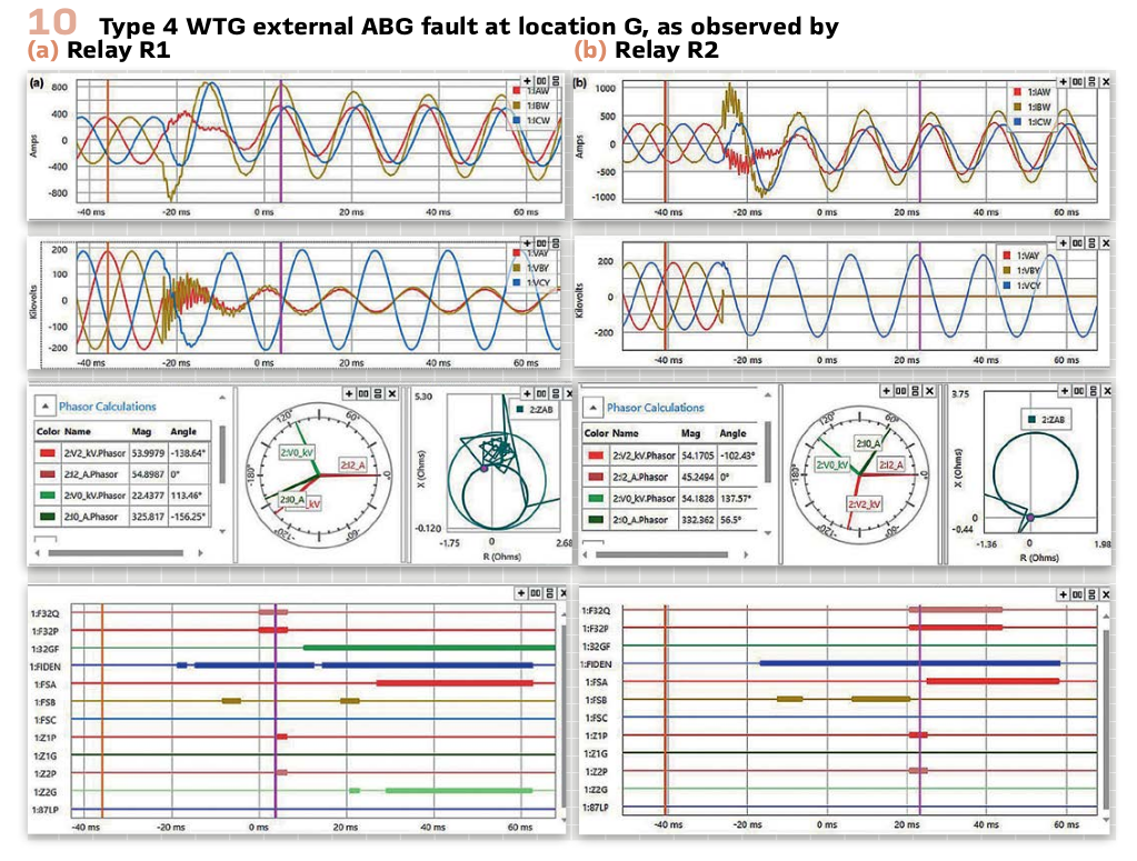
The fault generates an I2 of 55A primary (3I2 = 0.82A secondary) and an Io of 325A primary (3I0 = 4.88A). Rotation of I2 with respects to other signals creates the following issues
- Incorrect FIDS declaration, due to I2 rotating w:ith respect to I0
- Relay R2 incorrectly declares a forward fault direction, due to I2 rotating with respect to V2
- Relay R2 Zone 1 incorrectly operates for the close in external fault
- R1 overreaches on 21AB Zone1 for the forward fault at the remote bus due to an oscillating apparent impedance calculation caused by the rotation of I2
- Zone 2 of R1 drops out for the remote bus fault, this is a dependability issue
To understand the oscillating behavior on R2, we plot the real part of V2 and I2∠Z2L in Figure 11a. For a reverse fault, they should be approximately in phase, as V0 and (I0Z0L) are in Figure 11b. However, I2Z2L appears to have a higher frequency than V2. The result is that the I2Z2L phasor rotates with respect to V2, resulting in a loss of security and dependability for protection elements that use I2.
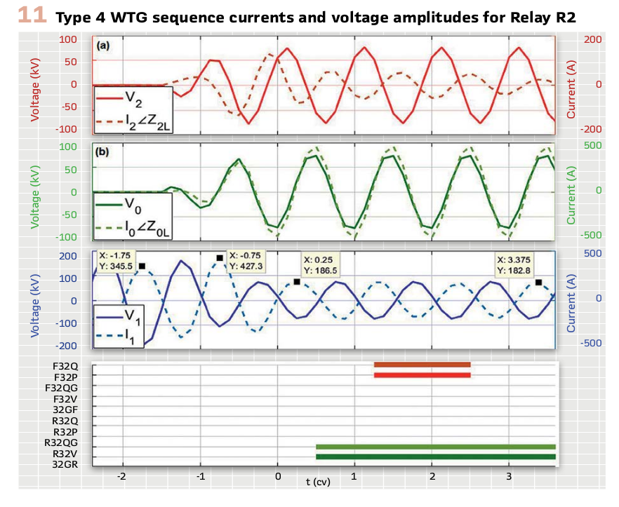
The I2 injected by the IBR can have a different frequency than the voltage. Conventional relays calculate the current and voltage phasors to protect the line, and a controlled current response from the IBR that loses coherence with the voltages can challenge line protection.
This behavior challenged LL and LG faults in a similar manner.
Type 3 WTG: The response from Type 3 WTG for unbalanced faults was much better than for Type 4 WTG. For an ABG fault at Location G, we made the following observations:
- The 32Q element is not challenged because I2 and V2 are stable
- The FIDS logic has sufficient I2 and I0 (selected FSC), correctly permitting 21AB to run
- Zone 1 on R1 overreaches
- Zone 2 on R1 drops out
I2 had a coherent frequency with the other signals, such as V2 and I0, allowing protection to behave reliably. This well-behaved response is due to Type 3 WTG effectively behaving as an induction generator, depending on the operating point, and the flux in the generator being maintained during the fault. Therefore, the generator provides sufficient and coherent I2 during a remote transmission line fault.
Type 3 WTG had trouble with 3P faults at Location G, unlike Type 4 WTG units, because a 3P fault decreases the flux in the generator more rapidly over time, and the loss of voltage at the generator terminals may negatively impact the frequency of the currents injected into the rotor. We observed that:
- R1 overreaches for a fault at the remote bus
- R2 loses directionality due to the IBR being isolated from the inertial frequency source, resulting in rotating current phasors. This results in a Zone 1 misoperation for the reverse fault
Unlike Type 4 WTG, Type 3 WTG behaved well for an LG fault, and all relay elements operated reliably.
Conclusions
The control scheme governing the behavior of IBRs generally has the objective of protecting the power electronic switches and the capacitor on the dc bus. For many present-generation IBRs, this typically manifest itself as low-magnitude currents that may behave poorly and incoherently with the voltages. Existing protection schemes that have been developed over several decades face several reliability challenges when only the IBR current contribution to the fault is measured by the relay.
This article presents the following challenges encountered by line protection schemes:
- The negative-sequence directional element and fault type identification may misoperate due to the currents injected by the IBR
- The phase directional element may misoperate when a three-phase fault disconnects the IBR from the power system
- Phase distance element Zone 1 may overreach because of an oscillating apparent impedance due to the currents injected by the IBR
- Phase distance element Zone 2 may drop out because of an oscillating apparent impedance due to the currents injected by the IBR
Biographies:

Ritwik Chowdhury received his BS and MS in Electrical Engineering in Canada. He joined Schweitzer Engineering Laboratories, Inc. in 2012, where is presently an engineer in the Research and Development division. Ritwik holds 5 patents and has authored over 15 technical papers. He is the chairman of two IEEE Standards Working Groups. Ritwik is a registered professional engineer in the province of Ontario.

Normann Fischer has a master’s in technology, with honors, from Technikon Witwatersrand, Johannesburg; a BSEE, with honors, from the University of Cape Town; an MSEE and a PhD from the University of Idaho. He was a senior design engineer in the Eskom protection design department for three years. Then he was a senior design engineer in IST Energy. In 1999, Normann joined Schweitzer Engineering Laboratories, Inc., where he is currently a fellow engineer in the R&D division. He was a registered professional engineer in S. Africa and a member of the S. African Institute of Electrical Engineers. He is a senior member of IEEE and a member of the American Society for Engineering Education (ASEE).