Ralph Mackiewicz, SISCO, Inc, USA
C-RAS lowers the cost of implementation by bringing the protection information into the control center where communications with SCADA-EMS, and its operators, can be implemented more cost-effectively. In C-RAS, the fault detection relays still perform the basic function of detecting fault conditions (line overloads, generator trips, etc.) that need remediation and the mitigation relays still perform the basic function of interfacing with circuit breaker controls to shed load when needed. But the role of each relay is simplified to the essential functions of executing the control and detecting faults.
In C-RAS the decision about what action to take is made by the central controller which has access to all necessary system information from the EMS and signals from all the relays across the system. Without C-RAS, the system complexity needed to deliver all this information to the relays necessary for them to make control decisions across the power system is much greater and increases cost extremely. The relay programming environment, specialized for protection functions, is not well suited to this kind of decision making. Because the roles of the relays in C-RAS are simplified and because the complex decision making is made from a central location, the development and testing of C-RAS can be done much more efficiently using significantly fewer devices.
Justification
The justification for implementing any automatic RAS processing system, centralized or not, is very substantial. The Northeast Blackout of 2003 and the San Diego Blackout of 2011 are examples of a power system experiencing a cascade failure. These power system failures cost many billions of dollars to the economy and many millions of dollars in costs to the utilities involved. In both cases, the utilities had some knowledge that the system was beginning to fail but manually operated RAS could not be executed quickly enough. Given that the system operators did not have enough detailed information about all parts of the system (e.g. 2003), the operators would not be able to execute their RAS operations quickly enough before the next line trip occurred.
As each new line or generator trip occurred, the contingencies changed which changed the RAS that needed to be executed. Even if operators have detailed information on the system, they might not be able to keep up with a fast-changing system (2011).
One of the most significant technologies to be developed that enables the implementation of C-RAS is the availability of high-performance protection relays supporting the IEC 61850 GOOSE protocols.
IEC 61850 GOOSE provides a mechanism for a relay to communicate its status to other devices using multi-cast messaging that supports 3ms end-to-end communications over substation networks. In a wide area network (WAN) environment, additional latency is introduced by network routers. However, with modern SONET fiber technology, such communications are very fast.
In practice, the C-RAS system in place supports response times of 50 ms from fault detection to mitigation being received across the entire network including RAS reaction times.
Proof of Concept
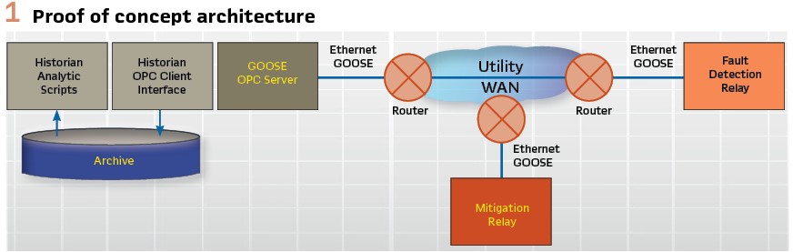
The idea of deploying a large-scale C-RAS was first considered beginning in 2006. Although a few wide-area GOOSE systems involving point to point links existed, nothing of the magnitude needed to build a utility-scale C-RAS system had been done before. It was necessary to first qualify that the technology of IEC 61850 could meet the performance requirements before proceeding to a pilot program. Therefore, a proof-of-concept project was initiated. The utility contracted with the author’s company (SISCO) and a protection relay provider (General Electric) to build a proof of concept in their lab using nothing but off-the-shelf software and hardware products. The goal was to show that the underlying technology could support the requirements.
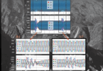
The team constructed a lab environment that used two protection relays. One to send simulated fault indications and the other to receive simulated mitigation messages using IEC 61850 GOOSE. Each relay was located in a substation and connected to the utility’s fiber WAN using routers. In the lab, a similar router was connected to a standard server computer running an Open Platform Communications (OPC) interface that subscribed to the GOOSE messages from the fault simulation relay and published messages to the subscribing mitigation relay. The server ran a popular data historian that monitored the GOOSE data generated by the relay using its OPC interface, run some basic logic, and create a simulated mitigation signal which would be sent to the mitigation relay. When the relay was triggered to generate a fault the latency and processing times of each component in the system were observed. (see Figure 1).
The goal was to be able to demonstrate that the system would be able to achieve a reaction time of 16 cycles (267 ms @60 Hz) from fault indication until mitigation received using these off-the-shelf components. (see Figure 2).
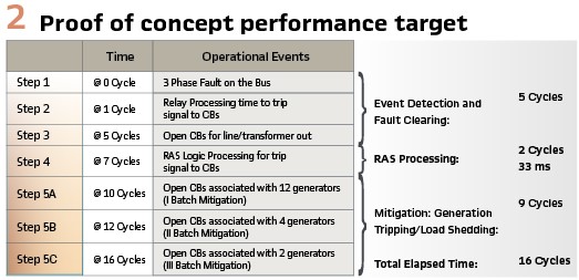
The results of the proof of concept were promising. Relay to relay communications over a distance of ~500 miles using the utility WAN and GOOSE was consistently 21 ms (<1.5 cycles @ 60Hz). RAS processing time using these off-the-shelf components was 40 ms. While the RAS processing target was missed by about 21%, all project participants considered that a purpose-built analytic environment that did not include historian processing in the RAS processing timeline would result in a solution that easily met the 33 ms target. The decision by the utility was to proceed to a pilot project to build an operational C-RAS solution, deploy it in the field, and evaluate the performance implementing a realistic RAS algorithm using protection relays connected to the power system in the utility’s substations.
Pilot Project
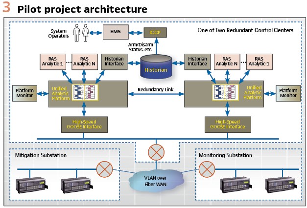
The goal of the pilot project was to implement a modest C-RAS solution to learn what it takes to make this solution operational on a large scale. The off-the-shelf interfaces and historian analytics used in the proof-of-concept were replaced with purpose-built solutions that would maximize the performance of the analytics and handle the GOOSE traffic very efficiently. The utility had already identified many RAS that they wanted to implement over the coming years which helped define future requirements as well. The knowledge needed to be gained from the pilot spanned many functional areas from RAS development to testing of RAS, networks, applications, and devices; how to maintain these systems and the impact of system expansion in the future. The pilot had to be sufficiently robust to obtain regulatory approvals for implementing their RAS schemes in the future. Gaining regulatory approval based on the pilot results was considered the measure of success for the project. (see Figure 3).
The pilot system was put into operation in 2007. Precise performance measurements across all the components of the system proved that all the performance requirements were met with a significant margin. Upon acceptance of the project, the RAS was put into operation temporarily and tested for compliance with the regulatory authority. Initial regulatory approval that would enable the utility to proceed with deploying additional RAS in the future was gained in 2008.
Operational Deployment
The pilot project proved that the basic C-RAS concept was practical. As the utility internalized those lessons, they realized that the scope of a project for a large-scale deployment needed to be expanded significantly if they were going to meet their long-range goals for a C-RAS system capable of executing many RAS analytics simultaneously with the required level of resiliency, performance, and operator control. It took about 3 years of study to develop a final set of requirements that could be put out to bid and procured. The new requirements expanded on all aspects of the existing C-RAS including:

- A dramatic increase in performance that reduced the fault to mitigation response from 267 ms to 50 ms and reducing the RAS reaction time requirement from 33 ms to 4 ms
- Performance requirements on CPU and memory utilization for all system components
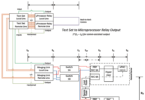
- Implementation of a highly resilient redundancy architecture that not only protects against system component failures but also enables system maintenance without impacting operations (see Figure 4)
- End-to-end latency monitoring including RAS processing, networks, and protection relay processing. A “ping relay” application was developed to measure the actual application to application latency across the network which can be monitored by system operators
- Security controls using role-based access control for applications and using syslog monitoring of the security environment
- The ICCP interface between the EMS and C-RAS system was replaced by web service messaging using a Common Information Model (CIM) format. The CIM defines a “master model” governing data exchange between EMS and C-RAS. The model used includes standardized power system concepts and has been extended to include modeling of RAS schemes, contingency lists, targets, mitigation points, etc. required for the C-RAS analytics. EMS operators monitor the C-RAS components, latency, RAS processing, etc. and also to enable/disable individual RAS, modify setpoints, etc. as needed based on system conditions
- Extensive new testing requirements were developed to expand the functional and performance testing a 30 RAS configuration that models 120 substations with 350 IEDs that are generating 800 GOOSE messages with 150,000 points of data about every 2 seconds. The testing would take place in four separate test cycles beginning with a Factory Acceptance Test (FAT) and three separate System Acceptance Test (SAT) cycles.
Resiliency
A key element of the new system requirements was the increased resiliency demanded of the system. As can be seen in Figure 4, the system is divided into two sides: A-Side and B-Side. While each shares the same redundant wide area network, each side includes a complete C-RAS system with its own RAS controllers, substation devices, substation networks, routers, switches, etc. Each side operates independently and simultaneously in two geographically separated control centers. For each mitigation and monitoring substation, there are always at least four IEDs: two redundant IEDs for the A-Side and two redundant IEDs for the B-Side that all monitor the same fault conditions or control the same breakers for mitigation.
Each side uses three RAS controller instances that operate simultaneously and where each RAS controller instance is comprised of two controllers in a dual-redundant configuration. Under normal operating circumstances there are six RAS controllers active and simultaneously operating (three on A-Side and three on B-side) and six RAS controllers in standby (receiving and processing data but not performing any mitigations) for a total of twelve RAS controllers.
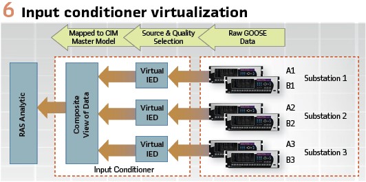
Each RAS controller has two GOOSE Interfaces. One interface for high-priority messages and another for low priority. Each RAS controller receives GOOSE from both the A-Side and the B-Side. Each RAS controller has an Input Conditioner (Figure 6) that virtualizes the IEDs to create a composite view of the GOOSE data. The Input conditioner chooses which GOOSE data the RAS analytic should use based on data quality and source. This simplifies the RAS logic and maximizes RAS performance. If there is no difference in the data available from either the A-Side or B-Side, the Input conditioner will preferentially select the data from its side.
Each active RAS controller (six-under normal conditions) processes composite data from the Input Conditioner and makes independent mitigation decisions. Each mitigation IED can receive GOOSE messages from all RAS controllers on its side (A-Side or B-Side). For a relay to perform mitigation, it must receive mitigation signals from at least two active RAS controllers on its side.
The only logic in the relay that is needed for the mitigation is a relatively simple voting scheme where at least two RAS controllers must be indicating that they are requesting mitigation. With this architecture, mitigation can still occur with one monitoring relay active, only two RAS controllers active, and one mitigation relay active on a given side.
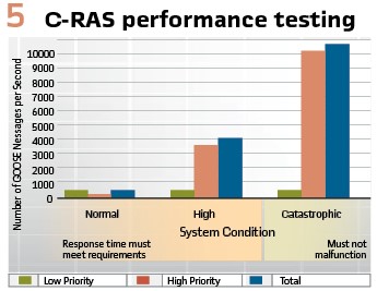
The architecture provides a great deal of resiliency and provides the flexibility to perform system changes, migrations, and maintenance. On any given side, the utility can take four RAS controllers off-line and still have a responsive system. This enables routine maintenance and upgrades to be performed without affecting system operations. Furthermore, the utility can take an entire side down to update relays, network equipment, and the like without affecting the ability of the system to perform mitigations when needed and without losing redundancy. (see Figure 5).
Migration to R-GOOSE
The first phase of the project described above used the GOOSE messaging of Edition 1 of the IEC 61580 standards (2003). In 2012, the IEC standards committee released IEC TR 61850-90-5:2012 which specified a new profile for using GOOSE messaging over an IP-Multicast network called Routable GOOSE (R-GOOSE). The R-GOOSE profile used the same application message specified for the original GOOSE but added some additional protocol elements that would provide security and allow the messages to be sent over an IP network using the Unsolicited Datagram Protocol (UDP). Furthermore, the R-GOOSE profile specified the use of the Internet Group Management Protocol Version 3 (IGMPV3) which enables the routers to automatically determine the routing path through the network without having to individually configure each router.
In 2016 the utility initiated a project to migrate the existing C-RAS system to R-GOOSE in addition to Ethernet GOOSE. All performance requirements remained the same (50 ms fault to mitigation and 4 ms RAS reaction times). Additional RAS were also added to the system. The migration was completed in 2018 with all performance requirements being met. Currently, the system is operating using both GOOSE for the previous RAS and R-GOOSE for the new RAS. Both kinds of RAS (GOOSE and R-GOOSE) are currently operational. A plan is in development to migrate the existing GOOSE to R-GOOSE and the utility will only use R-GOOSE in the future. The utility is currently in the process of adding several new RAS to their system using R-GOOSE.
Securing R-GOOSE
The existing R-GOOSE network used by the utility is quite secure. There are extensive physical and cybersecurity technologies and processes in place to protect the integrity of the C-RAS system. Routers use Virtual Private Network (VPN) technology to protect the data while it is in transit. There is robust physical security on all aspects of the C-RAS system to prevent unauthorized access to the physical equipment involved. The C-RAS components themselves use role-based access control (RBAC) along with Active Directory (AD) authentication to ensure that only those with the correct level of privilege can access C-RAS functions even with physical access to the computer.
The R-GOOSE profile of IEC TR 61850-90-5:2012 included the protocol elements necessary to secure GOOSE, R-GOOSE, Sampled Values (SV per IEC 61850-9-2) and Routable Sampled Values (R-SV). These elements provided the means to perform strong authentication using digital signatures and encryption using symmetric key technologies. Since 2012, the state of the art of security technology has advanced considerably and the contents of the IEC TR 61850-90-5:2012 specification were updated and then moved into the IEC 62351 series of standards which specify the security profile for IEC 61850 and other IEC protocols. Many IEC 62351 standards address various aspects of securing IEC 61850 systems, but this article is going to focus on those standards related to securing R-GOOSE for C-RAS systems:
- IEC 62351-6:2020. This standard specifies the security profiles for all of IEC 61850 including GOOSE, R-GOOSE, SV, and R-SV. While the security profiles are primarily connected with securing the routable profiles only, the technology can be used to secure non-routable profiles. This standard specifies the packet structure for sending the necessary security protocols in R-GOOSE and R-SV packets
- IEC 62351-9:2017. This standard specifies the communications protocols and profiles for implementing a Key Distribution Center (KDC) and for the key management functions needed by devices for securing R-GOOSE and R-SV. The KDC is responsible for authenticated all components in the system and issuing them the symmetric keys needed by these components to encrypt, decrypt, sign and authenticate R-GOOSE/R-SV messages
The KDC is a critical component in automating the processing required to completely secure R-GOOSE and R-SV messages in a large-scale system. Without a KDC, each application would need to interact with the devices to negotiate the symmetric keys needed to do the encryption/decryption functions. With hundreds (and maybe many thousands) of devices and computers, the complexity of such a system increases exponentially. Configuring and managing such a system is not practical.
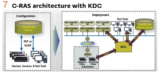
The KDC simplifies the system substantially by centralizing the management of which devices and applications are authorized to access which GOOSE/SV data streams and to distribute symmetric encryption keys to them that allows them to process the data streams without having any additional interactions with the source of the data streams. The KDC enables a utility to build end-to-end security for R-GOOSE and R-SV in a manageable manner. As specified in the IEC 62351-9 standard, the KDC makes use of several protocols to implement its functions that are summarized below and are illustrated in Figure 7.
Secure Certificate Enrollment Protocol (SCEP) and/or Enrollment over Secure Transport (EST). These two protocols are used to obtain digital certificates (e.g. X.509). These protocols provide a secure method for a Certificate Authority (CA) to generate/sign certificates for the devices and applications that it trusts in such a manner that the private certificates can be kept completely private and hidden. The signing server generates both a private and a public certificate.
The private certificate is used by the device or application to create signatures that other applications can use with the public certificate to authenticate that only the device with that private certificate could have generated that signature. The private certificate would never be used outside the device or application.
Group Domain of Interpretation (GDOI). GDOI is used by the KDC to distribute the symmetric encryption keys to all the entities publishing and subscribing to an R-GOOSE or R-SV data stream. A device that is publishing an R-GOOSE Control Block would first establish a secure communications channel with the KDC using GDOI over Transport Layer Security (TLS).
The device then requests the key to use for the R-GOOSE Control Block and generates a signature in the request. The KDC authenticates the signature and assigns the symmetric key used to encrypt the R-GOOSE messages. Similarly, any device or application that must subscribe to that R-GOOSE Control Block also uses GDOI to obtain the same symmetric key so that it can decrypt the R-GOOSE messages.
Online Certificate Status Protocol (OCSP). This protocol is used by the KDC to validate that the certificate used in a signature has not been revoked by the CA that signed that certificate. If the certificate was revoked, the KDC would not authenticate the application/device when it tried to establish a GDOI connection with the KDC. Typically, there is a hierarchy of CAs that allows a utility to use a different CA to generate and sign certificates for C-RAS that may not be the same CA that every other application in that utility would also have to use.
The resulting system allows every application or device in a system to have public and private certificates with strong asymmetric keys that can be used to authenticate each device or application and to obtain the more computationally efficient symmetric keys over a secure channel that enables authenticated devices and applications to sign, encrypt, and decrypt R-GOOSE message exchanges.
Currently, the utility is planning to implement secure R-GOOSE in a future system expansion. There is a concern that the implementation of encryption for the R-GOOSE messages might impact system performance and RAS reaction times unless hardware-based encryption accelerators are used. There is a lot of interest in implementing security for R-GOOSE based on regulatory and corporate risk analysis.
Biography:

Ralph Mackiewicz is VP of SISCO, a developer of communications and integration products for electric utility applications located in Sterling Heights, Michigan. Ralph has a BSEE from Michigan Technological University. Ralph is an active participant in several IEC and IEEE PSRC/PSCC standards activities and has expertise with IEC 61850, ICCP – TASE.2, Common Information Model (CIM), OPC and ISO 9506 (MMS). Ralph is currently Chairman of the Board for the UCA International Users Group and participates in the CIM Users Group, IEC 61850 Users Group, IEEE and CIGRÉ activities. When Ralph is not pursuing his passion of interoperability, and when the water is not frozen, he and his wife enjoy their boat by fishing on beautiful Lake St. Clair which is situated between the US and Canada north of Detroit.