Andre Smit, Dr. Alexandr Stinskiy, and Suraj Chanda, Siemens, USA, and Christopher Huff, Southern California Edison, USA
The modern distribution grid is rapidly evolving with increased penetration of Distributed Energy Resources (DERs). This transition requires an advanced distribution automation system with new protection & control algorithms, which can account for dynamic changes in load flow and energy resource availability while performing fault localization, isolation, and load restoration to maintain stability and reliability of the grid.
The architecture of the advanced distribution automation system can be centralized, decentralized, or a combination of both. To achieve the fastest system response, authors believe distribution automation intelligence should reside at the grid’s edge. Such an approach ultimately allows protection algorithms to work in conjunction with automatic load restoration functions at the IED level in the field. Thus, compared to a centralized solution, minimizing the amount of data exchange with a Distribution Management System (DMS).
In the decentralized system design, field automation controllers work together as a team to resolve fault scenarios, governing circuit switching responses in pre-defined geographical areas. Each participating controller or team member employs its system logic while incorporating local measurements and information received from other team members into its decision-making process.
For a given fault event, the latency of the communication infrastructure limits the overall system response time. Previously authors designed and deployed a decentralized distribution automation application utilizing a legacy radio communication system and serial based DNP3. This article will introduce a new phase of the project, where the system employs the IEC 61850 protocol with GOOSE messaging and cellular LTE communication. Authors are introducing a bridging concept where multiple individual circuits with distribution automation controllers can share relevant information and work as a single team to address any fault scenarios. This approach will simplify the deployment and expand the overall scale of the distribution automation system. The neural network-based decentralized logic will perform rapid calculations of available energy resources and determine suitable load restoration scenarios for any fault scenario. With the utilization of a high-speed communications infrastructure and the IEC 61850 standard, the authors plan to demonstrate a sub-second system response time.
Project Goals
Southern California Edison’s (SCE) current distribution automation technology relies heavily on human intervention. SCE’s current switch automation technology utilizes a Switch-and-a-half (1½) switching scheme per circuit, capable of automatically isolating half of the load on an affected feeder. In response to a fault condition, SCE’s Grid Operations can take several minutes (or longer under storm conditions) to analyze the system and perform additional switching operations to reduce the fault’s impact to customers further.
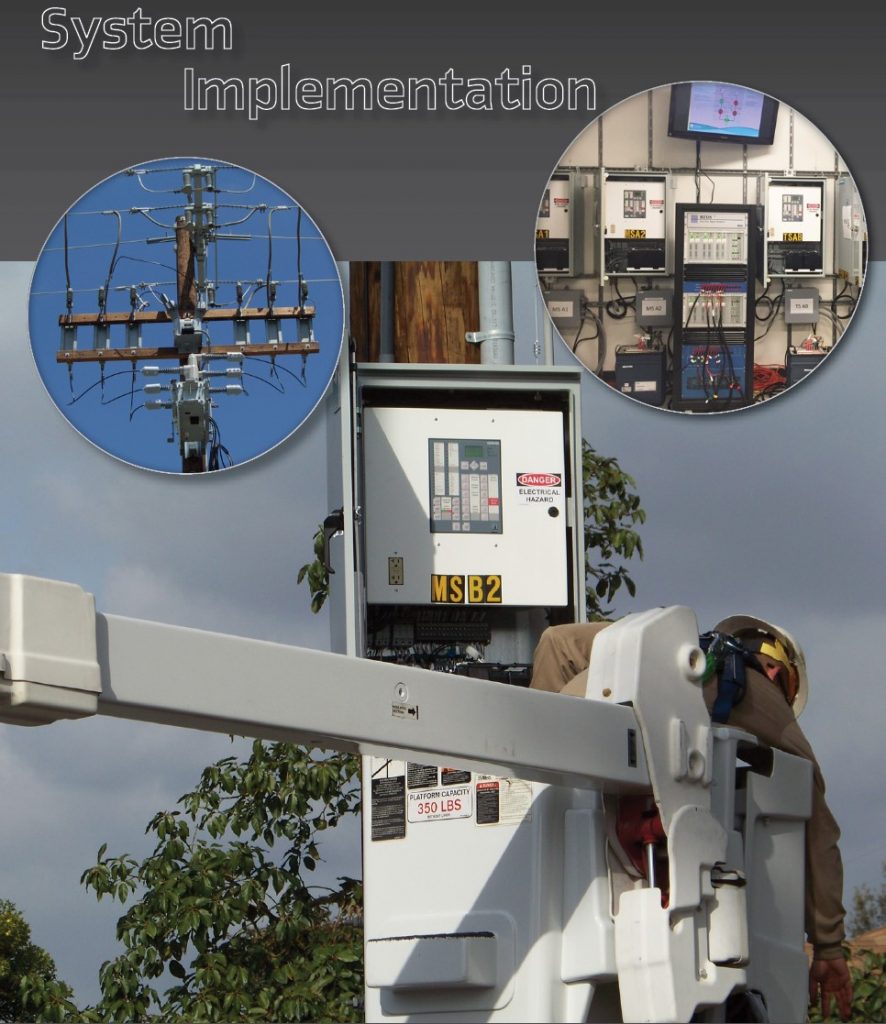
SCE commissioned the Next Generation Distribution Automation project under the Electric Program Investment Charge (EPIC) program to address these challenges. As part of this project, SCE is implementing a new switch automation technology, referred to as the Remote Integrated Switch (RIS). The RIS includes a new control and communication scheme.
The following is a list of goals SCE is attempting to accomplish with the RIS project:
- Advanced automation for fault detection and auto circuit reconfiguration
- Improve System Average Interruption Duration Index (SAIDI) and Momentary Average Interruption Frequency Index (MAIFI)
- Quickly interrupt and isolate fault conditions
- Restore non-faulted interrupted load quickly without operator intervention
- Incorporate greater levels of telemetry to support SCE’s Distributive Energy Resources Management System (DERMS)
- Communication-based coordination between substation relays and mid-switch operations
- Use open and standardized communication protocols
- Use non-proprietary control and communication solution
- Interoperability with various interrupters, communication systems, protocols, and other deployable field devices; and
- Capable of supporting various circuit topologies and communication conditions
Low-Speed System Architecture
The Low-speed system architecture application was implemented during previous phases of the RIS projects to seamlessly integrate into SCE’s existing distribution protection and coordination schemes with minimal modification to existing infrastructure. This architecture does not rely on substation SCADA communication for coordination with the substation relays. The substation breaker operation is detected by the Loss of Voltage Automatic (LVA) feature, resulting in the first downstream RIS isolation operation if the circuit’s line voltage is missing for 30 seconds. For fault interruption, RIS controllers use protection curves coordinated with the substation relays and downstream devices.
This architecture employs SCE’s existing communication system, a radio mesh network on the unlicensed 900 MHz spectrum. The radios support a 9600 baud rate serial interface utilizing the DNP3 protocol and a usable packet size limitation of 207 bytes. SCE’s radio network covers 50,000 square-mile, with approximately 55,000 radio terminals installed in the field. The inherent communication latency and packet size limitation result in relatively long system reconfiguration times.
Engineering Challenges in low-speed System Architecture
Many engineering challenges were encountered and subsequently resolved during the project’s Low-speed communication phases:
- Creating peer-to-peer data exchange with DNP3 protocol
- Data packet size limitations
- Overcurrent protection challenges
- Miscoordination with the substation breakers
- Operational-group size limitation
- System logic design
- Complex system logic configuration
- Communication performance in the field
While the authors accomplished their goal to demonstrate 14 RIS devices utilizing DNP, due to the limitations of the DNP3 protocol and relevant communication infrastructure, the authors confirmed the system could not extend beyond a 14 devices operational-group. With a device count increase, the system response time grows disproportionally due to communication latency. The authors focus on solving these problems in the High-speed system design utilizing the IEC 61850 interface and new circuit bridging concept.
High-Speed System Architecture
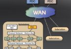
The High-speed system architecture will provide a significant feature set advancement due to its enhanced data management capabilities. The design of this architecture is to support deployments with a low latency communication infrastructure utilizing the IEC 61850 standard with GOOSE messaging. Unlike the Low-speed architecture, this system will not require a DNP router for peer-to-peer data exchange, thus eliminating a single point of failure. This configuration consists of RIS controllers in the field and at least one RIS Substation Gateway. The RIS Substation Gateway interfaces and coordinates system operations with the circuits’ relays at the substation. Communication with DMS will utilize the DNP protocol.
The decentralized logic architecture governs the individual RIS operations. The decentralized architecture can provide fast and efficient operations as protection and automation functions reside within the microprocessor based RIS controllers at the edge of the grid. To govern the system’s response to various fault scenarios, SCE designed a set of operational rules which shall be automatically followed.
The fast system response is essential to maintain distributed energy resources for the load restoration actions following the fault event. The following factors limit the system operating speed:
- Communication latency peer-to-peer
- System logic processing time
- Switchgear operating time
In this application, the communication infrastructure will support latencies in the range of 100s milliseconds for peer-to-peer data exchange, thus providing a sub-second system response. The communication latencies, however, may vary depending on the traffic. In the RIS system, authors define several GOOSE datasets with different priorities to avoid a “GOOSE avalanche,” i.e., a sharp increase of traffic when multiple devices send GOOSE messages simultaneously in response to a fault event. Without special precautions, this could lead to a significant latency increase and several dropped packets.
- To optimize the system’s processing time, the authors introduced several logic task levels
- Fault processing level
- Load processing level (load calculation, restoration path determination)
- Control processing level
The fault processing level is the fastest portion of decentralized system logic. It operates only with binary signals and performs the time-critical tasks such as fault location determination, fault tripping, zone isolation, a fast portion of the instantaneous capacity restoration check algorithm (ICRC), and load reconfiguration. The GOOSE messages associated with this logic have short retransmission times and the highest system priority. The processing time within the RIS controllers’ embedded PLC is 10-50 ms.
The load processing level is responsible for source budget & load calculation, ICRC, and restoration path determination. It operates with analog and binary signals, consuming the majority of the PLC’s memory. The processing time may vary depending on the availability of the incoming GOOSE indications. To optimize the logic’s performance and data management, the load processing level is triggered periodically when the system is idle, not responding to a fault event. Once triggered, it calculates the available load and determines three restoration scenarios for all individual RISs. The RISs saves these scenarios in memory until the next calculation cycle. Should a fault occur, the RIS controllers will check which scenario is available for the fault event and perform the necessary operations governed by the fault processing logic.
The control processing level is triggered when grid operations changes the system’s mode-of-operations or operates the RIS location. This logic task is not time critical.

SCE designed a complex circuit topology to test the high-speed system architecture. Figure 1 shows this topology. The topology includes 6 circuit breakers tied to an infinite bus to represent substation sources, 16 RIS field devices, and one non–RIS DNP3 based automated device. Each topology line segment may potentially have a distributed energy resources connection. The purpose of the non-RIS device is to evaluate operating conditions where circuits are connected or bypassed through manually or automated (non-RIS) switches.
The design of a typical IEC 61850 based system includes multiple IEDs and GOOSE messages sharing control, status, and operational data between devices. In the IEC 61850 standard, the GOOSE datasets may be broadcasted from one IED to all IEDs in the system, or multicasted from one IED to a select few IEDs.
This approach works well for deployments with a fixed number of IEDs and a firm system structure. The RIS project goal is to support various circuit topologies. Therefore, GOOSE dataset configuration may be different for different topologies.
Another challenge of a conventional IEC 61850 system is the reprogramming requirements of all IEDs if a new device is added to the system, subscribing pre-existing IEDs to new device datasets. Authors identified IED reprogramming as a significant challenge for a wide-scale system deployment.
With many devices in a single group, the conventional approach for the decentralized system, where every device receives information from all team members, is not practical, requiring the communication system to establish permanent data channels between each pair of RIS controllers. To address this problem, the authors introduce a circuit-based approach with the following highlights:
- Split the sizeable operational-group into smaller groups, where the small groups are circuit-based, including devices from one circuit (circuit breaker, several mid switches, and tie switches, connecting circuits)
- Perform the peer-to-peer data exchange only between devices within these small groups, formed by a circuit
- The RIS devices which physically connect two or more circuits will form the logical and communication bridge to transfer data and operational decisions between circuits
- A new circuit deployment only requires enabling the logical bridge, eliminating the need to update the entire system
- Deploying a new circuit device will require reprogramming all the circuit’s devices, but not the entire RIS system
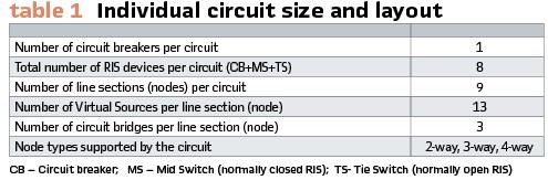
The following parameters define the individual circuit size and layout (see Table 1).
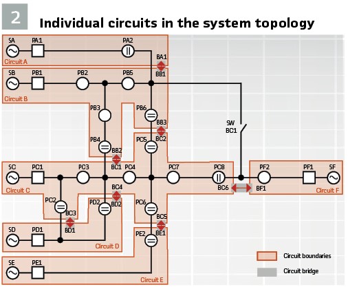
According to this concept, the system topology in Figure 1 represents six individual circuits (circuit A…F). Each feeder has a substation source, a breaker, and several RIS devices connecting the line sections within the circuit boundaries. When two or more circuits are connected, the RISs form a logical bridge to transfer operational data between the feeders. Logical bridges include unique logic on the RIS hardware and communication channels between adjacent devices. Figure 2 shows individual circuits and their corresponding logical bridges.
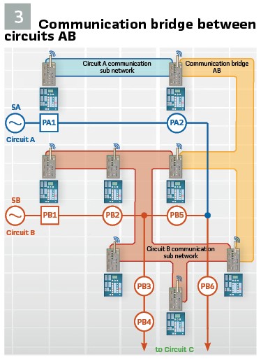
Figure 3 depicts a graphical representation of the communication bridge between circuits A and B. Circuit A is formed by breaker PA1 and tie switch PA2. The controllers of these two devices share data through GOOSE messages on a peer-to-peer basis. The breaker PB1 forms the neighboring Circuit B, mid switches PB2, PB3, PB5, and tie switches PB4 and PB6.
Within Circuit B, the controllers share data amongst themselves. Controllers PA2, PB5, and PB6 establish a circuit bridge to exchange data between Circuits A and B. All relevant data from Circuit A will be provided by device PA2 to devices PB5, PB6. In turn, PB5 and PB6 devices will provide circuit B data to device PA2.
The system logic is configured in the form of a neural network to establish the data flow between devices, perform necessary calculations, and eventually generate the operational decisions. The data will flow in both directions through the system logic between three devices PA2, PB5, and PB6. In this example, devices PB1, PB2, PB3, and PB4 are not communicating directly with either PA1 or PA2. Relevant circuit information is shared outside of the circuit boundaries only by devices forming a bridge.
Once circuit C is ready for deployment, RIS controllers PB4 and PB6 will create a bridge to the adjacent circuit C controllers. The new logical bridge with circuit C eliminates the need to update devices on circuits A or B. The bridge will be ready to accept data from circuit C once it becomes available. To establish the bridging logic between two circuits, only the communication devices (cell modems or any other wireless network terminals) addressing information needs to be updated.
Circuit Bridging Logic
The bridging logic connects individual feeder circuits to an operational group with the RIS fault isolation and reconfiguration capabilities. Every device shall support up to 3 bridges in every direction (Direction D1(Y) and D2(Z)) to be able to establish a logical connection with up to 3 other circuits forming a 4-way node.
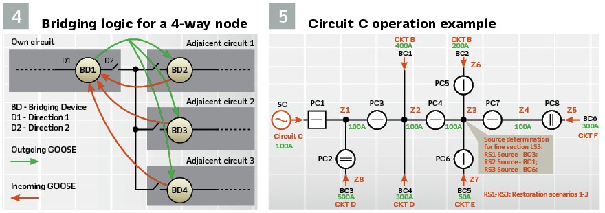
Figure 4 provides an example of a 4-way node. The arrows indicate outgoing and incoming IEC 61850 GOOSE routings.
Some of the data shared between devices include the following GOOSE signals:
- Faulted Circuit – indicates that the circuit has an active fault
- Detected and Isolated Fault – indicates that the circuit has an active and isolated fault per the Zone Isolation Rule (ZIR)
- Isolate Request – a signal to other bridging devices to isolate the line section from the opposite end for a faulted line section. The incoming tag provides a request to this bridging device to isolate the faulted zone according to the Zone Isolation Rule (ZIR)
- Reconfigure Request – a signal to a bridging device to pick-up its circuit
- Maximize Circuit Reserve (MCR) Flag – is issued when MCR conditions are fulfilling on the circuit. A faulted circuit meets the requirements when it does not have a pre-existing connection to a neighboring circuit, and the system can transfer the load with minimal switching operations
- Node Connection – signal becomes TRUE when a bridging device has a physical connection to another neighboring bridging device or circuit node (i.e., a manual switch or non–RIS device). In turn, the outgoing signal is FALSE when a physical connection to a bridge device is missing, or there is an open circuit node (i.e., a manual switch or non–RIS device is open). The status information for the manual switch or non-RIS device is provided through DMS via DNP3 to the nearest RIS controller. This indication is needed to account for the scenario where the actual and default system topologies differ due to temporary circuit configuration
- Maximum Source Budget – Provides the available budget capacity for the preferred sources (circuit), typically the circuit with the highest capacity
- Connected Load – provides the total load value for a given device may need to transfer to another circuit during a fault event
- Disconnected Load – provides the total load value a given device may transfer to an alternative source (other than the preferred source) during the fault event
- Source Path – provides the device count to the preferred source on the own circuit. Incoming indications provide device count to the preferred sources on the other circuits
- DER Offset – provides the DER capacity connected to the line section between this bridging device and device from the other circuit. Incoming indications provide the DER capacity connected to the line section on the adjacent circuits
A few other GOOSE signals are shared for the jDiffTM algorithm to perform fault location across the circuit. The GOOSE routing and respective logic compilation can be automated through Computer-aided design software to simplify the application engineering and deployment efforts.
System Operation Examples
Figure 5 outlines the Circuit C topology. Typically, Circuit C is fed from its source (SC) and connected to four other circuits through the bridging logic BC1-BC6. Under normal operating conditions, devices continuously perform restoration determinations for every zone Z1-Z8. The bridging logic at device PC2, PC3, PC4, PC5, PC6, and PC8 receives the remaining-budget value from its adjacent circuit and transmit this information for ICRC calculation. Each bridging device presents a unique restoration path. Each device identifies three restoration scenarios (RS) for every load zone:
- RS1 is the most desirable scenario for load restoration, and it will select the source with the highest available load budget
- RS2 is the alternate restoration scenario for the source available to the line section’s left
- RS3 is the alternate restoration scenario for the source available to this line section’s right
These three scenarios are pre-determined by the slow portion of ICRC logic. Based on the fault location and availability of the RS1-RS3 sources, the circuit’s RIS controllers selects the restoration scenario.
Figure 5 depicts the normal conditions, with available source budgets, for Circuit C and the bridging devices to other circuits. For load zone Z3, since Circuit D has the highest remaining-budget and is accessible through tie switch PC2, it is the best restoration option. Restoration Scenario 1 (RS1) will represent a Circuit D (connected through bridge BC3) restoration. The RS2 source shall be different than RS1, and upstream of load zone Z3. Circuit B, with available 400 A remaining budget, is chosen for the RS2 restoration scenario. Circuit F with available 300 A remaining budget has a downstream connection to Z3; therefore, it will represent restoration scenario RS3. The system performs similar calculations for other load blocks.
The following examples explain system reaction under fault conditions:
Source C Fault – If source C is lost, zones Z1-Z4 will be de-energized. Following the circuit breaker (PC1) operation, the RIS controllers will check if the path to the RS1 source is un-faulted. In this scenario, the system will follow the RS1 source restoration scenario and close PC2.
Z1 Fault – A fault in this zone will cause PC1 to trip and PC3 to isolate. Since the RS1 option is faulted (a Z1 fault interrupts the path to bridge BC3), RIS controllers will discard the RS1 option and check RS2. The path to bridge BC1 is un-faulted; therefore, BC1 will close, bridging Circuit B.
Z2 fault – A fault in this zone will cause PC3 to trip and PC4 to isolate. Since the RS1 option is faulted (a fault in Z2 interrupts the path to the bridge BC3), RIS controllers will discard the RS1 option and check RS2. In this scenario, a fault is on the bridge BC1 path; therefore, the system will discard the RS2 option. Devices will follow the RS3 option and close PC8.
For Z4, Z6, and Z7 faults, upstream devices will perform the isolation operation and will not affect the default supply from source SC.
Conclusion
Following the development of a slow communicating distribution automation application, the authors introduce a new circuit based high-speed RIS system. The proposed design utilizes the IEC 61850 standard with GOOSE messaging to achieve a fast system response to fault events. One of the benefits of high-speed restoration operations is maintaining distributed energy resources for load restoration operations following the fault event.
A decentralized neural-based system can achieve this benefit with load calculation at the edge of the power grid, where the communications system only limits speed. Computer-aided design software can overcome scalability limitations and simplify the application engineering and deployment process.
Biographies:

Andre Smit completed his studies at the Vaal University of Technology in Power Engineering in South Africa in 1988. He joined Siemens in 1989, working in the field of protective relaying for the past 32 years. He specialized in generator protection systems. Current position is P&C Product Manager including Distribution Feeder Automation systems. He is the principal inventor of the SDFA Distribution Automation System and holds various patents on new methods to protect and automate distribution feeders. He is a member of the IEEE.

Alexandr Stinskiy Ph.D. is a senior application engineer for Siemens US where he develops Distribution Feeder Automation products. He graduated from Pavlodar State University, Kazakhstan, with diploma in Relay Protection and Automation. He defended his thesis, “Improvement of Current Protection for Distribution Grid” in 2009. Alexandr holds 19 patents in the area of protection devices and algorithms (including two US patents) and has worked as a consultant in the field of power industry, energy savings and efficiency. Alexandr joined Siemens in 2010.

Suraj Chanda MSEE, MBA is an application engineer for Siemens USA where he configures and tests automated electrical power distribution systems. He graduated in 2011 from Texas A&M University, College Station, Texas, USA with Master of Science degree in Electrical Engineering. He defended his thesis, “Modeling the Effect of Hurricanes on Power Distribution Systems” in 2011 at College Station, US. He joined Siemens as an application engineer in 2011. He plays a major role in designing, programming and testing of FLISR projects. Suraj received his MBA degree from Duke University in 2018.

Christopher Huff is a Professional Engineer licensed in the State of California practicing in Power Engineering. He is a Senior Engineer for Southern California Edison SCE’s Advance Distribution Management System (ADMS), where he has ten plus years of experience researching, designing, and implementing SCADA systems to support advanced power distribution. Christopher’s significant engineering projects include SCE’s Distribution Management System (DMS), Distribution Volt Var Control (DVVC), and decentralized FLISR applications. Currently, Christopher is researching and developing new technologies for the SCE’s Grid Technology Innovation laboratory in Westminster, California, USA.