by Walter Schossig, Germany, and Thomas Schossig, OMICRON electronics GmbH, Austria
In Germany the VDE Working Group 0435, working on protection, was founded in 1955. It was in 1962 when they published the document “Guidelines for Relays in High Voltage Systems („Regeln für elektrische Relais in Starkstromanlagen“) (Figure 1).
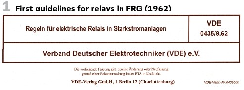
The guidelines have been on working and operation of protection relays and measurement. The TC 41 at IEC, which is the corresponding international standardization body was founded in 1960 (“Protection relays”). An updated version of the German guideline was published as VDE 0435/9.62.
For the type test the vendors received guidelines on what to test:
- Startup and fallback of the relay and the corresponding times for all types of relays
- Operating times, zone values and directional sensitivity for distance relays.
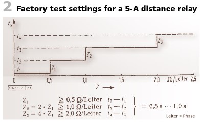
For the distance relays it was the recommendation to test with the doubled nominal value. Phase shift should be considered. For overcurrent startup relays the smallest value shall be chosen. Under-impedance relays shall be tested with the smallest startup current possible. To achieve proper results the first value for 5-A-relays should be more than 0.5 Ohms/phase, at 1A not below 2.5 Ohms/phase. It was also recommended to work with certain settings (Figure 2).
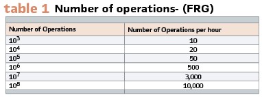
To detect the error limit of the operation time 10 measurements have been recommended. Tolerances have not been defined within the guideline, because this should be defined by the vendors in their manuals. To test the durability during type, test a number of operations was proposed (see Table 1).
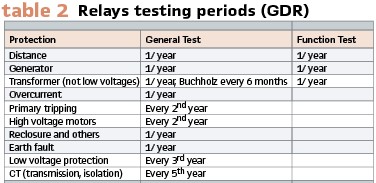
In Eastern Germany, in the German Democratic Republic (GDR), behind the Berlin wall there was only one vendor of protection devices called EAW. Existing VDE guidelines have been replaced since 1961 by own standards called TGL (Technische Güte- und Lieferbedingungen – Technical Value and Delivery Conditions). Effective from the beginning of 1962 TGL 78-2 3311 defined testing periods. They have been mandatory for utilities as well as vendors and construction companies in the GDR (Table 2).
The general test included tripping, measurement values and characteristics. The functional test included startup, timing and trip, but without measurement values. The startup can be triggered manually or by current injection.
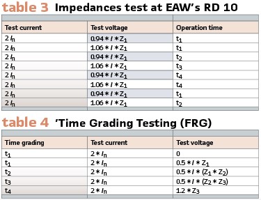
At the end of the 1960s the scientific-technical center (Wissenschaftlich-Technisches Zentrum) together with the operators defined an own guideline for relay operation (“Richtlinie für den Relaisdienst. “) This document explained in detail what belonged to the test- ON/OFF coil of circuit breaker, measurement transformers, wiring, isolation. CB characteristic, Buchholz and contact thermometer, overcurrent, distance, earth fault and generator protection. Also values to be injected as well as tolerances could be defined (Tables 3, Table 4).
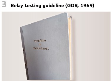
This guideline was mandatory for every relay tester in the GDR (Figure 3).
In the 1960s it was common practice to add a primary injection to the test of protection and measurement transformers during the commissioning. This allows proper testing of differential protection. A 3-phase fault was built in the low voltage wiring- once within the differential protection zone and once outside the zone. On the high voltage side 380 V (400 V) 3-phase alternating current are connected. For transformers ≥110 kV generators could be used (Figure 4). This so called “differential suitcase” consisted of 9 multi meters to measure the currents on both sides and inside and outside the differential zone. If the short circuit was outside, the smallest differential current value was recorded. At the end stage the differential current shall be 20% of the testing current. To power up a transformer the line to the power station had to be connected. During the short circuit trial only Buchholz shall be active, line protection shall be inactive. If the phone connection interrupts, the test shall be stopped immediately. After the current trials a voltage trial was added. With 0 to 80% of all the steps the controller was tested. The Koske-device measured high-frequency emissions.
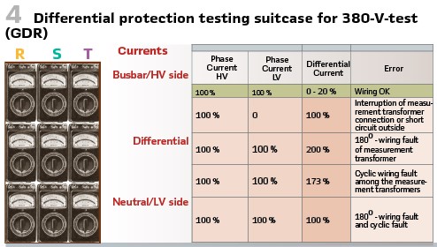
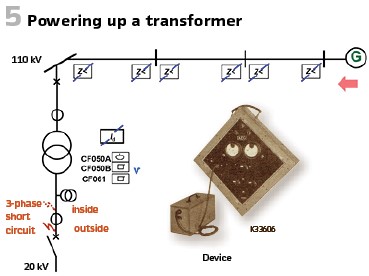
To minimize the impact of inrush several tests on operations have been performed. For the differential 0.3 s had to be added. If the time would be > 1s, the startup value of the differential relay had to be increased.
AEG proposed for the check a testing device capable to deliver 50 Hz as well as 100 Hz (controllable).
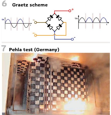
In the GDR a system was developed to simulate the inrush effect in that manner, that rectifiers eliminated the half-waves. The pulsing DC simulates the inrush current (complete flux transmission, Figure 6).
During the tests at this time automated testing was already a topic. After the phases have been connected, the current was increased, and the operating time could be recorded. A paper recording device worked with 20 mm/s and creates the protocol automatically.
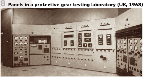
It was in 1960, when the PEHLA was founded as the association of all high-voltage test laboratories in Germany and nine years later a guideline was published. It was the goal to certify, that at nominal short circuit currents (e.g., 16 kA) during a period of 1 s, persons close to the switch cubicle could not be harmed (Figure 7). This should be also valid for the adjacent cell. Slightly adapted, this is still valid today as IEC 62271.
F.E. Wellman was with the company A.E.I. (Associated Electrical Industries Limited) in London (UK). It was in 1968 when he published his book “The protective gear handbook”. Chapter 14 of this book is covering principles of protective gear testing and maintenance.
Protective gear differs from other types of electrical equipment in that for most of its useful life it is inoperative, as it is designed to operate only under abnormal conditions. Such conditions are often difficult to reproduce for testing purposes. The importance of correct operation, however, is so great that all possible means should be employed to ensure that the protective gear, together with all its associated equipment, is always in a condition to operate correctly should a fault occur. It is generally convenient to coordinate the maintenance and testing of protective gear with the maintenance of the associated items of large equipment such as switchgear or transformers.
There were several principles given as a general guide to be applied with suitable modifications to any particular equipment. Tests are generally arranged to demonstrate:
a) That the equipment will operate correctly to clear a fault
b) That the protection will remain inoperative on faults outside the specified zone
The most complete tests were during the development by the manufacturer. In order to reproduce accurately the conditions which, arise in transmission and distribution systems during faults, the equipment for providing the current for these tests, particularly in the case of high-speed types of protection, must be of considerable capacity and special design. To ensure that the behavior of the protection under transient conditions is fully proved, it is often necessary to assemble the complete protective equipment comprising relays, CTs, auxiliary equipment, and, when they are involved, simulated pilot circuits having appropriate constants.
The test equipment must be capable of supplying and controlling very heavy currents of pure sinusoidal waveform in circuits having a mainly reactive impedance. The use of switching devices designated to initiate a fault at any desired point on the voltage wave permits the repeated application of faults with any required degree of initial asymmetry. This is important since transient DC components arising from the asymmetry may cause saturation on some of the CT cores and materially affect the stability of the protective gear. In addition, apparatus is required to observe and record the value, shape and duration of the test currents, and record the times of operation of the various elements.
The control element of a typical test equipment is shown in Figure 8. In this case it was a 10-MW motor-generator or the public supply was used to feed a 5-MVA transformer stepping down from 6.6 kV to 200 V. This was designed to give three-phase currents up to 20000 A directly, or the equivalent of multiples of this value by using more than one primary turn on the CTs of the protective equipment under test.
An alternative, lower-power, arrangement uses smaller currents but many primary turns on the CT cores to obtain the required Ampere-turns. This was fed from a medium -voltage source, control of the current being obtained by switching of reactors designed to give a high X/R ratio in the test circuit.
Other tests described in detail are:
- Demonstration tests
- Routine manufacturer’s tests
- Purchaser’s preliminary tests
- Commissioning tests on site
- Routine and maintenance tests
- Tests after relay operation
- Special tests.
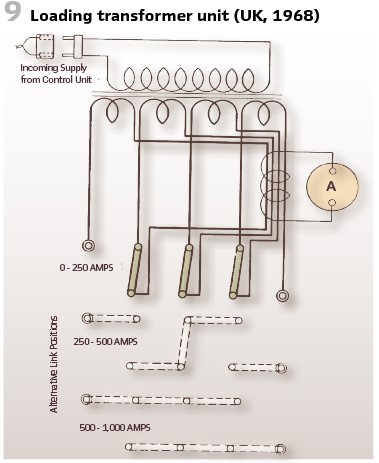
Let’s have a look on the testing on site. Considering precautions to be taken (safety, documentation) the requirements for the test instruments (robustness) and wirings were discussed. Also, on site primary injection tests have been common practice. In primary injection tests, heavy test currents are passed though the primary windings of the CTs concerned. Sometimes it was possible to obtain suitable currents by running a generator on short-circuit, but the test currents are generally obtained from portable or sometimes “transportable” injection transformers. These heavy-current testing transformers were usually single-phase units, with tests being carried out on individual phases or groups of phases of the protective gear. They were generally wound for a primary input voltage of 240 V or 415 V, often with some tappings for other voltages, and a secondary output of either 10 or 20 V. Provision was often made for connecting sections of the secondary windings in serial or parallel. The diagram of o typical primary injection transformer is shown in Figure 9.
This has a primary winding suitable for connection to a supply of either 110 or 240 V. Control may be obtained by a supplying it from a variable-voltage transformer, from tappings on a separate voltage controller or by using a secondary-injection test set as a control.
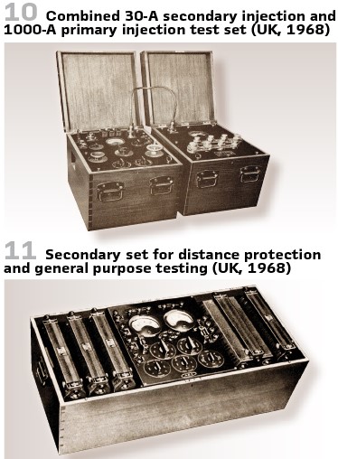
The secondary winding is wound in four sections, each rated at 250 A, 2 V which may be connected in series pr in parallel depending upon the impedance of the test circuit and the required value of current. The maximum secondary voltage with the coils in series is 8 V. The weight of this transformer is 350 lb. The control board of this transformer connected to 30-A-secondary test set is shown in Figure 10.
Difficulty of access to the primary windings of the CTs sometimes limits the use of primary-injection methods. This could also happen because of the presence of other CTs on the same bushing.
Primary injection tests may be used to prove the connections, polarity and ratio of the CTs, or alternatively in a combined overall test of the CTs and the protective relays. It is generally preferable, however, to carry out the tests on the relays by what was called secondary injection, i.e. by injecting currents and voltages directly into the relays themselves. This was because the currents are smaller and more easily handled and controlled than primary-injection currents under the conditions which probably obtain on site. Comparison with later routine maintenance tests was also easier. These secondary-injection tests on the relays preceded or followed the primary injection tests on the CTs.
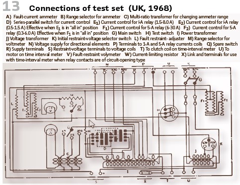
Secondary injection tests have already been common practice at this time. Some have been purchased and the engineers had their own preferences. For some simple tests on overcurrent relays simple equipment delivering 30 A at 15 V for short periods combined with time interval meter was sufficient. Such an equipment could weigh less than 60 lbs. A somewhat similar set to give 50 A at 20 V could weigh 90 lbs. A more complete set for general use is illustrated in Figure 11 and 13.
This set was designed for testing both 1A and 5A relays including directional and distance relays, up to about 6 times their rated current. The test set weighs 150 lb.
Also, functional and tripping tests have been mandatory, initiated by hand or from other associated functions. Additionally closing functions should be tested at 80% of the normal battery voltage, and tripping functions at 50 per cent.
For making the connections to the relays there were several alternative methods. One was to disconnect the relay on one side from the CT feeding it and to carry test connections from the test set to the relay in the back of the cubicle. This had the drawback, that connections have to be disturbed and they could not be replaced until testing is complete. The other option was to feed the injection current to the relay terminals by two clips, leaving the CT connections in position. Split plugs could be used (Figure 12).
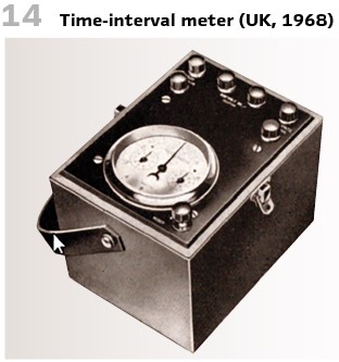
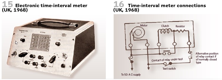
To measure the time, time-interval meters could be used (Figure 14). The first electronic meters appeared at this time (Figure 15).
To connect the meter a scheme was used as illustrated in Figure 16.
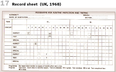
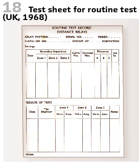
The successful application of protective gear requires a documentation system, by which the comprehensive history of installation, maintenance and operation can be built up. A suggested form is shown in Figure 17. Also test sheets have been used (Figure 18).
To be continued with a second part in the next issue.
info@walter-schossig.de www.walter-schossig.de
thomas.schossig@omicronenergy.com
Biographies:

Walter Schossig (VDE) was born in Arnsdorf (now Czech Republic) in 1941. He studied electrical engineering in Zittau (Germany) and joined a utility in the former Eastern Germany. After the German reunion the utility was renamed as TEAG, Thueringer Energie AG in Erfurt. There he received his master’s degree and worked as a protection engineer until his retirement. He was a member of many study groups and associations. He is an active member of the working group “Medium Voltage Relaying” at the German VDE. He is the author of several papers, guidelines and the book “Netzschutztechnik
[Power System Protection]”. He works on a chronicle about the history of electricity supply, with emphasis on protection and control.
Thomas Schossig (IEEE) received his master’s degree in Electrical Engineering at the Technical University of Ilmenau (Germany) in 1998. He worked as a project engineer for control systems and as a team leader for protective relaying at VA TECH SAT in Germany from 1998 until 2005.
In 2006 he joined OMICRON as a product manager for substation communication products. He is author of several papers and a member of standardization WGs.