Testing Devices in the 1990s (Part 2)
by Walter Schossig, Germany, and Thomas Schossig, OMICRON electronics GmbH, Austria
In the last issue we covered the first devices released in the 1990s. There is a lot of material available. So, let’s continue.
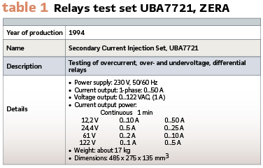
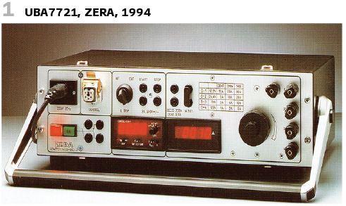
The company ZERA is well established in 1994. There are several testing devices for relays available at this time. They could be used for testing an overcurrent relay, over- and undervoltage protection. Also, differential protection could be tested with Secondary Current Injection Set UBA7721 (Figure 1). To test differential protection three devices could be used, operated via integrated control. (Table 1).
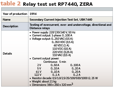
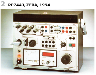
To test also several relays including directional relays the test equipment RP7440 was presented in the same year (Figure 2, Table 2). This was for single phase testing.
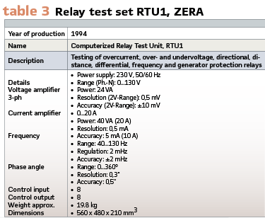
1994 was also the year, where the control via computer was presented at Hanover Fair by ZERA. The device was called RTU, the German name was “Rechnergesteuerte Prüfeinrichtung” (RTU1). The solution with software is shown in Figure 3. The main characteristics:
- Fully electronic generation of test parameters
- 3-phase voltage system (130 V)
- 3-phase current system (20 A)
- Frequency range: 40-130 Hz
- Control via PC
- Automatic test protocol storage
- Programmable test procedure
- Graphic display characteristics
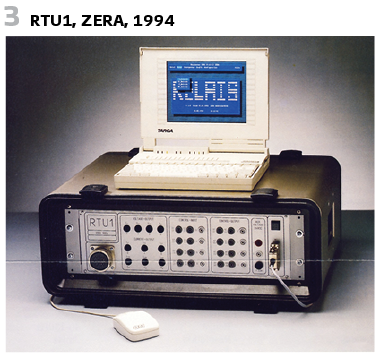
This device was a further development of RP86. A new hardware concept was released. All amplifier and other components have been pluggable. This increased reliability and ease of servicing. All technical data have been according to the definitions of Germany’s national working group at VDEW “future protection”.
The software came from ZERA, the hardware was made by Spitzenberger + Spies.
Software system features:
- Powerful test language
- Integrated standard tests
- Mouse operated
- Context sensitive help
Table 3 summarizes again the system features.
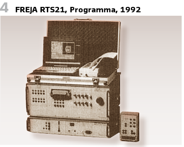
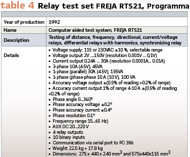
Programma came with their FREJA series device RTS11 in 1989. A further development was called RTS21D (1992, Figure 4). FREJA devices could be used for the testing of most types of relays. The test system provides three voltages and three current outputs that can be controlled individually or controlled with respect to each other. The system was supplied from a single-phase source. The output quantities of the test system are independent of the supply source, e.g. the test system could give out voltages with 16 2/3 Hz or 60 Hz frequency even when supplied from a 50 Hz source. The technical data can be seen in Table 4.
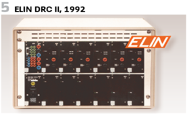
In Austria the vendor ELIN, also producing protection and excitation systems, developed an own Digital Relay Calibrator DRC II in 1992 (Figure 5).
It could be controlled already via Windows software. Since the voltage amplifiers could be switched to current amplifiers, differential relays could be tested as well.
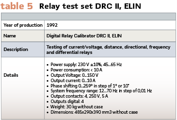
The design was modular. The common system frequency was adjustable in a wide range to cover railway systems (16 2/3 Hz) as well as 50 Hz and 60 Hz systems. The integrated time/ event recorder permitted the measure of time delays of delayed and un-delayed protective relays. (Table 5).
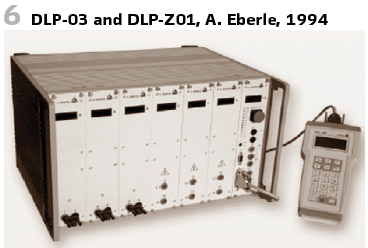
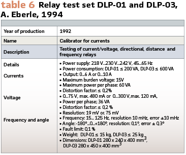
A. Eberle in Germany delivered calibrator for currents DLP-01 and DLP-03 in 1994 (Figure 6 ) to check measurements transformers, meters, and relays. Type DLP-03 came with 3 voltage sources and 3 current sources. The values had to be entered manually via handheld control DLP-Z01. The testing device came with a housing made of aluminum and was equipped with handles. (Table 6).
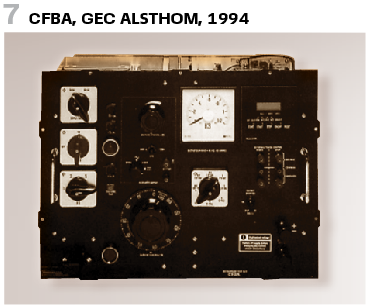
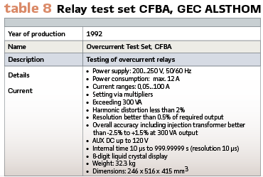
GEC ALSTHOM produced an own Overcurrent Test Set CFBA in 1994 (Figure 7, Table 8).
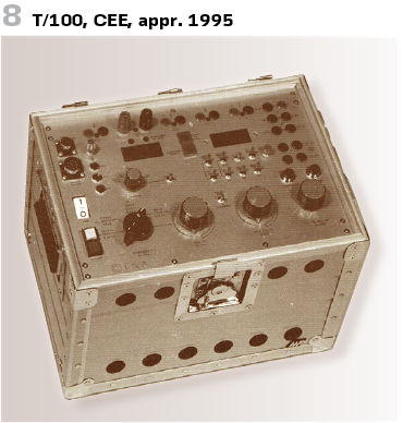
In 1995 CEE produced the single-phase relays test set T/100 (Figure 8). The T/100 – came with metal housing and consisted of three independent generators:
- Main: Current, AC voltage and DC voltage
- A1: for second AC voltage
- A2: for DC supply during relay testing.
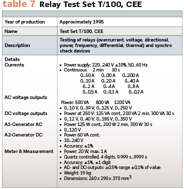
The device was delivered with additional capacity and set of resistances. This could be used for testing directional relays and power relays (90° phase shift). The outputs could be controlled continuously, the measurement was already digital. The auxiliary devices REF/100 and D/100 allowed testing of frequency relays, synchro check devices and differential relays. (Table 7).
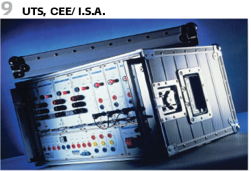
In the 1990s the Italian company ISA (CEE/I.S.A) entered the market as well- with single-phase as well as three-phase devices. The UTS was a universal test system for relays (see Figure 9). It was the second series of microprocessor-controlled test sets. The modular system consisted of two parts: UTS/MT Single-phase current and 3-phase Voltage source for single-phase testing. The UTS/T was the 3-phase source for currents and voltages and allowed testing of several relays including auto recloser.
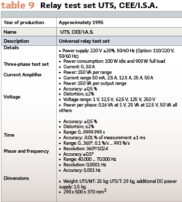
Also, this test set came in housing made of aluminum. The cover could be dismounted. (Table 9).
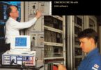
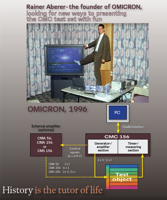
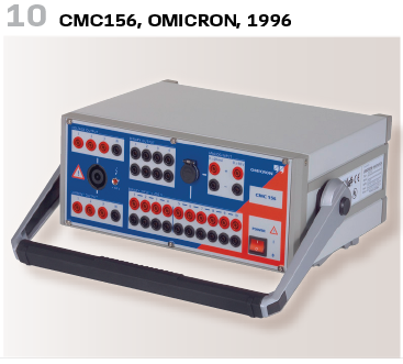
OMICRON was already mentioned in the last issue of the magazine. In 1996 the new 3-phase-test set CMC156 was presented (Figure 10). OMICRON has set new standards for advanced three-phase testing equipment in terms of flexibility, accuracy, portability and reliability. OMICRON´s PC-controlled test sets generated the test signals digitally (DSP technology), resulting in highly accurate testing signals even at small amplitudes.
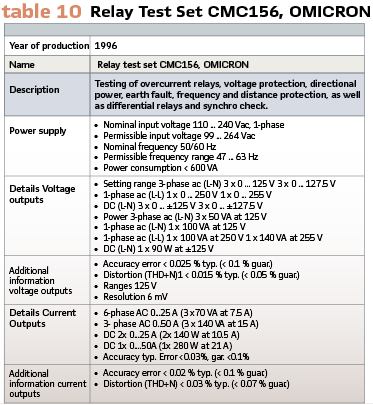
The electronic design of the internal amplifiers and the use of switch-mode power supply units ensure a minimum of weight and volume was achieved. Independent channels with low-level signals have been available at the back of the test sets, which could be used to control external amplifiers for applications requiring more signal channels or higher currents, voltages or power. The low-level signals could also be used for test objects which have a low-level input facility.
All generators have been continuously and independently adjustable in amplitude, phase and frequency. No switching of ranges was necessary. (Table 10).
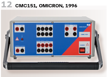
A variant with enhanced precision was called CMC156EP and could be launched in 1996. There was also the wish for single phase devices, and so the CMC151 came out (Figure 12).
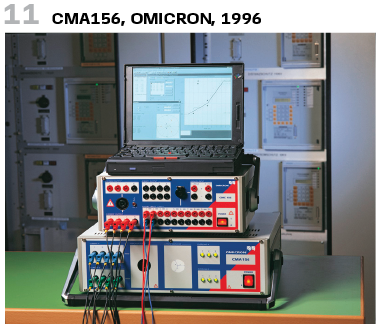
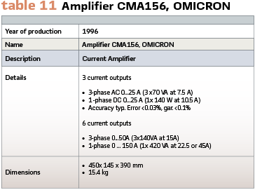
There was always need for amplifiers and thus OMICRON developed them at this time as well. So, the CMA156 was the six-phase current amplifier (Figure 11, Table 11).
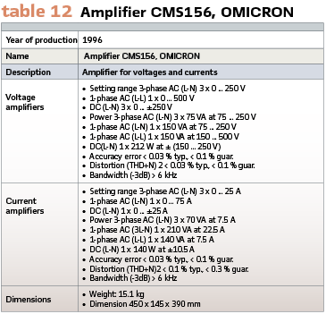
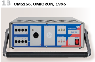
If higher currents and/or voltages have been needed a three-phase voltage- and current amplifier was released at the same time. It was called CMS156 (Figure 13, Table 12).
This should finalize this part.
We are still in 1996, and there is more to come describing what was happening in the 1990s.
walter.schossig@pacw.org www.walter-schossig.de
thomas.schossig@omicronenergy.com
Biographies:
Walter Schossig (VDE) was born in Arnsdorf (now Czech Republic) in 1941. He studied electrical engineering in Zittau (Germany), and joined a utility in the former Eastern Germany. After the German reunion the utility was renamed as TEAG, Thueringer Energie AG in Erfurt. There he received his master’s degree and worked as a protection engineer until his retirement. He was a member of many study groups and associations. He is an active member of the working group “Medium Voltage Relaying” at the German VDE. He is the author of several papers, guidelines and the book “Netzschutztechnik [Power System Protection]”. He works on a chronicle about the history of electricity supply, with emphasis on protection and control.
Thomas Schossig (IEEE) received his master’s degree in electrical engineering at the Technical University of Ilmenau (Germany) in 1998. He worked as a project engineer for control systems and as a team leader for protective relaying at VA TECH SAT in Germany from 1998 until 2005.
In 2006 he joined OMICRON as a product manager for substation communication products. He is author of several papers and a member of standardization WGs.