by Thomas E. McDermott, Pacific Northwest National Laboratory, and Sakis Meliopoulos, Georgia Tech, USA
Acknowledgement: The work is supported by the U.S. DoE Office of EERE under SETO Agreement 34233.
We thank Dominion and Chattanooga EPB for their strong support even during the Covid-19 pandemic.
In 2018, IEEE Standard 1547 was completely revised to, among other things, allow distributed energy resources (DER) to ride through voltage disturbances. There are three ride-through categories of DER; category III intended for “high penetration” DER scenarios. The sponsor, US-DoE Energy Solar Energy Technologies Office (SETO), envisions DER levels up to 100% of feeder peak load. The project targets this “high penetration” scenario.
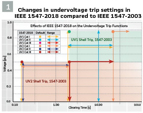
Figure 1 shows the impact of IEEE 1547-2018 on the undervoltage (UV) trip functions mandated for all DERs. From 2003 through 2014, DERs were required to trip when the voltage dropped below 0.50 per-unit for 0.16 seconds on any monitored phase.
The magenta area of Figure 1 indicates this “shall trip” region. In many instances, this UV trip served as a de facto or backup fault detection method, especially for DERs that are inverter-based resources (IBR). The UV function also serves as backup islanding detection method. In the 2018 revision, the default UV trip settings were increased for all three disturbance categories, i.e., all of the default setting points moved downward and/or to the right (Figure 1). Of particular importance is the UV2 setting for Category III. The default is 0.50 pu at 2.0 seconds. The ranges of adjustability were introduced in IEEE 1547a-2014, and the latest revision clarifies that a voltage trip set-point may be reduced all the way to zero and the time up to 21 seconds. If that is done, it removes the magenta area from Figure 1 and effectively disables UV2, meaning that it no longer serves as a de facto or backup fault detection.
A functional requirement in IEEE 1547-2018 dictates that DER must detect and clear faults on the connected circuit, independent of UV1 and UV2. Some large DER installations use communication-based schemes, e.g., direct transfer trip (DTT). Cost and complexity in multi-circuit and multi-DER configurations are considerations and a barrier to distributed PV integration.
To reduce these barriers, SETO sponsored this project to identify alternative methods of distribution system protection, particularly methods that could be implemented with off-the-shelf hardware. The scope was limited to radial, medium-voltage distribution circuits with OC based protection and considered advanced schemes used on transmission systems. The project team included PNNL, ORNL, Georgia Tech, Dominion Energy, and Chattanooga EPB.
Candidate Schemes
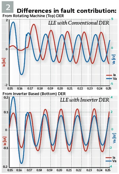
Figure 2 illustrates the fault characteristics of synchronous machine DER (left) and IBR DER (right). In both events, the voltage (blue) drops to 0.5 per-unit about 0.167 seconds into the simulation. The fault is some distance away from the DER point of common coupling (PCC) and the voltage at the PCC goes near the UV2 setting. Before fault initiation, the DER produces at unity power factor and the current (red) is in phase with the voltage. During the fault, the synchronous machine current increases to about 5 times normal and lags the voltage by nearly 90 degrees. The DC offset in the fault current decays within a few cycles. The IBR behaves like a controlled current source, so it responds differently to the fault. The fault current contribution increases to only about 1.15 to 1.20 times rated, as the IBR control attempts to limit the current magnitude within operating limits. The fault current lags the voltage only for the first cycle. Afterward, the IBR phase-locked loop (PLL) brings the current and voltage back into phase. Both magnitude and phase of IBR fault current are different from that of synchronous machine.
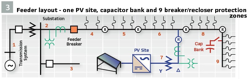
Figure 3 shows a generic distribution feeder considered in this project, with one large PV system. The utility partners provided data for three feeders, having from one to three large PV each. Ultimately, the new protection schemes must scale up to feeders with many more PV installations, including hundreds or thousands of rooftop PVs. All three feeders include several line reclosers, as indicated in Figure 3. The feeder breaker provides directional primary protection for zone 4, and secondary protection for zones 5-9. The recloser at the PV site provides primary protection for zones 4-7, and secondary protection for zones 8-9. It should not trip for faults in zones 1-3, but it may be difficult to distinguish those faults from others because the IBR voltage and current won’t change very much. In particular, the need to ride through faults on the transmission system, represented by zone 1, led to the desensitization of UV1 and UV2 in IEEE 1547-2018. From the IBR fault contribution characteristics, we don’t expect conventional time-overcurrent or distance relays to work properly at the PV site.
Travelling Wave Functions
Travelling wave (TW) protection functions are available now in both double ended and single ended schemes. Both require precise timing and the double-ended requires high bandwidth communications. Single ended TW, operating on the difference of arrival times between modal traveling wave components, is more attractive for distribution systems to minimize communication costs. In an earlier project, we demonstrated the function working on a simplified IEEE test feeder, augmented with features as:
1) three-phase branches
2) single-phase laterals and
3) distributed service transformers with high-side equivalent capacitances.
TW did not scale up to larger circuits with many more distributed transformers and taps, multi-grounded neutral conductors, and especially switched capacitor banks that are common on distribution feeders. When a switch first closes into a de-energized capacitor bank, the event generates traveling waves similar to those from a fault; therefore, it is hard to distinguish from a real fault. Furthermore, only the first travelling wave arrival offers the chance to detect a fault, as multiple reflections from the multiple transformers and taps in distribution lines attenuate the waves. We did not attempt to use a TW function in the field trials.
Incremental Distance Functions
The incremental distance, or time domain distance (TD21) function is based on waveform processing and may be available in the same relay that provides TW function. This idea dates from the 1970s as a method to achieve fast relay times on ultra-high voltage transmission. It seemed promising based on the first cycle IBR fault current behavior in Figure 2 (bottom), and some preliminary work in. Summarizing the algorithmic principles from and publicly available manuals:
1. Upon triggering, the relay constructs and filters incremental (deltaV) voltages and currents based on the difference between present-time instantaneous values, and the values from previous time samples for all channels.
2. The incremental currents squared must integrate to a threshold and be of the correct sign to pick up the forward directional function, TD32.
3. The incremental currents must also reach a threshold to pick up the overcurrent supervision function, OC21. The OC21 threshold depends on the line impedance, Z, and compensation, m, settings.
4. Finally, the incremental distance function, TD21, must pick up based on a comparison of the operating and restraint quantities, both of which depend on current, voltage, Z, and m.
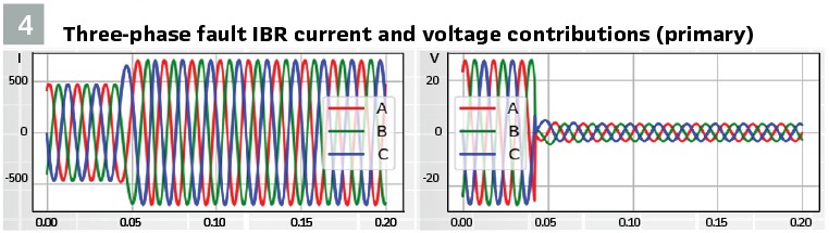
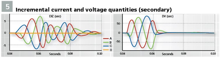
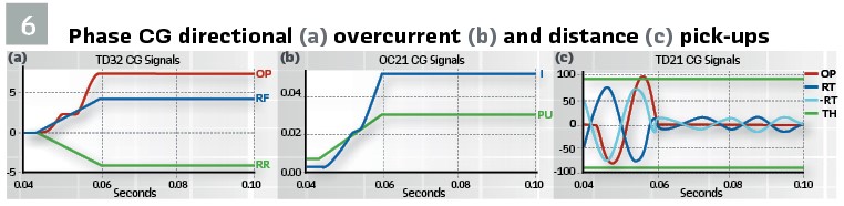
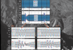
If all four steps activate, the relay generates a trip signal. Figure 4 shows the simulated IBR currents and voltages at the PCC for a nearby three-phase fault, and Figure 5 shows the derived incremental quantities (zoomed in) during the fault. The relay typically makes the trip decision during the first cycle. The IBR behavior is based on a textbook inverter model simulated in Alternative Transients Program (ATP). In the field, each inverter will behave a little differently. For this example, Figure 6 illustrates the phase C-to-ground decision signals. TD32 (a) picks up when the operating quantity (OP) exceeds the forward restraint (RF). OC21 (b) picks up when the current (I) exceeds the pick-up threshold (PU). Both TD32 and OC21 are based on time-domain integration of the signals, thresholds and offsets. TD21 (c) picks up when the operating quantity (OP) exceeds the restraint (RT) with correct polarity; this is based on signal comparison. Other details for this relay can be found in the final report.
Estimation-based Protection
The estimation based protection (EBP) was introduced as a robust solution to address: (a) complexity of present day protection and control systems, EBP provides a simple secure and reliable approach without the need to coordinate with other relays, (b) reduced fault currents due to the increasing converter interfaced generation; EBP does not depend on fault current levels, (c) new characteristics of fault currents due to IBRs, i.e. reduced or lack of negative and zero sequence fault currents; EBP is immune to these issues, and (d) required speed in detecting faults; EBP detects fault in fraction of milliseconds.
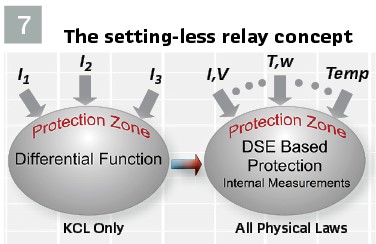
Figure 7 depicts EBP next to a differential protection function; both do not need coordination with other relays. In differential protection, the electric currents at all terminals of a protection zone are measured, and their weighted sum must be equal to zero (KCL). As long as the sum is zero or near zero, no action is taking. In DSE based protection, all existing measurements in the protection zone are utilized, currents and voltages at the terminals of the protection zone or inside the protection zone (as in capacitor protection) or speed, temperature and torque in case of rotating machinery or any other internal measurements. The dynamic model of the device (consisting of physical laws such as KCL, KVL, motion laws, thermodynamic laws, etc.) is used to provide the inter-relationships among all measured quantities. When there is no fault within the protection zone, the measurements satisfy the dynamic model of the protection zone.
A quantitative assessment of how well the measurements of the zone fit its dynamic model in real-time is performed via dynamic state estimation (DSE). The measurements are processed with the DSE which computes the best estimate of the protection zone states. It also computes the goodness of fit or the probability that the measurements “fit” the zone model within the accuracy of the metering used (via the well-known chi-square test). The chi-square test typically returns a probability of 100% for healthy protection zones and 0% for a protection zone with any type of internal fault.
Overcurrent Directional Functions
A focused directional scheme (Function 67) works well with synchronous machine DER, but not so well with IBR. There are transient changes in the relative current magnitude and phase angle from IBR during a fault, but as indicated in Figure 2, the current magnitude is near normal and the phase angle quickly returns to zero. Function 67 would not trip dependably during this transient. The transformer in Figure 3 has a high-side delta winding, as is often the case, and it would not provide ground current, defeating the directional ground overcurrent. If all DER on a feeder provided ground current, that would desensitize feeder ground fault protection, so many utilities won’t allow it.
Negative Sequence Functions
For rotating machine DER, negative sequence current (Function 46) and negative sequence voltage (Function 47) have been useful complements to other protection functions. IBR controls are designed to suppress negative sequence current during unbalanced conditions. There is usually a negative sequence transient current immediately after a fault, but that does not provide a dependable operating quantity. Some national norms call for IBR controls to allow negative sequence currents during faults which could simplify protection of high penetration DER circuits during unbalanced faults.
Model Adaptive Protection
The Model-driven Adaptive Relay (MDAR) was developed at ORNL to deal with increasing complexity and demands on modern electric systems. The relay works as follows: the MDAR performs an automated study to established updated settings based on the prevailing operating conditions. By allowing the relay to update in real time, protection settings may act more precisely than traditional relays that need to account for all operating conditions. The MDAR works by applying traditional relay functions (50, 51) in a flexible and dynamic way. For example, the 50 and 51 settings may vary according to the fault current strength and DER connection, as estimated from the relay model. The MDAR performance is being investigated with Monte-Carlo simulations.
Analysis Procedure for TD21
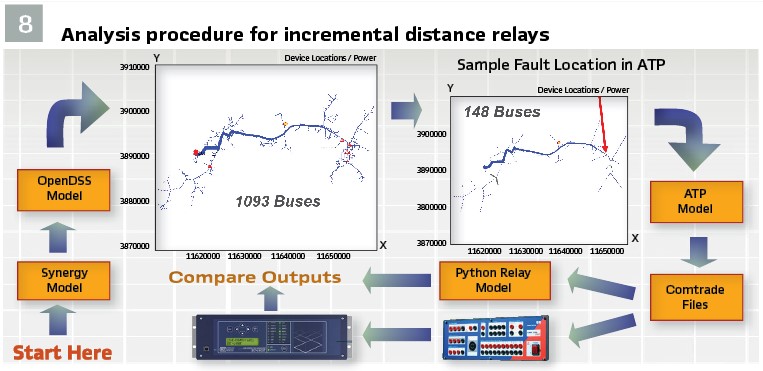
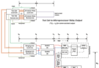
Figure 8 illustrates the feeder modeling and relay analysis procedure for applying TD21. The utility feeder model be converted to the open-source OpenDSS format. OpenDSS has a fast phasor solution mode to simulate a sequence of fault initiation, trips, reclosing and lock-out until the fault is isolated. At the end of the sequence, some circuit segments may experience a momentary or sustained interruption. We use this mode to establish baseline protection system performance with traditional relay functions, i.e., time-overcurrent, instantaneous overcurrent, undervoltage, overvoltage and reclosing sequences.
The OpenDSS model is also converted to ATP. ATP includes detailed time domain IBR PLL model. Scripted fault simulations were performed to:
1) Check TD21 settings and models under different fault conditions
2) Generate CNN training data
3) Create COMTRADE files for open-loop relay tests in the lab. These tests included a TD21 relay, and a feeder/DER protection relay with functions 50, 51, 46, 47, 67
A time-domain relay model in Python was used to predict TD21 performance during IBR-fed faults. The relay model algorithm was validated by running the same input waveforms into the relay model and into the open loop tests of the actual relay and comparing the results. The model was derived from phasor-based equations provided by the vendor, but a few relay parameters were unspecified and not adjustable. The effort paid off when we identified some heuristics to adjust the settings, so that OC21 would pick up for most of the IBR-fed faults.
Sample Results
Sample results are based on three unpublished utility feeders and two public feeders. One is the IEEE 8500-node test case for residential rooftop PV. The other is the EPRI-J1 distributed PV feeder with four commercial-scale PV and several residential PV.
Incremental Distance
The incremental distance (TD21) function was dependable, selective, and secure at the substation; at the PV sites, it was not dependable for faults near the substation, based on simulations. The field trials included a variety of real IBR, but the detailed control models were not available. This would add to the uncertainty of future applications at PV sites.
Estimation-based Protection
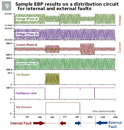
Example Operation of an EBP relay is shown in Figure 9. The protection zone is a section of a distribution line belonging to one of the partner utilities. The figure illustrates two successive faults and the response of the EBP. The first fault is an internal fault initiating at t=0.429s. The second fault is outside the protection zone, initiating at t=0.938s. Each fault duration is 0.215s. For brevity we show the voltage and currents at the two ends of the distribution line section of the faulted phase only. The last three traces (5, 6 and 7) show results from the dynamic state estimation. Trace 5 shows the computed chi-square (sum of the residuals squared). Only during the internal fault this quantity is substantially higher than zero. Trace 6 provides the probability that the measurements are consistent with the model of the protection zone within the accuracy of the measurements. This probability goes to zero only during the internal fault and it is 1.0 for the rest of the time except with a small transient around t=1.152 sec. Finally, trace 7 provides the trip signal.
Lessons from Field Trials: Only a few months of data were collected because of the pandemic. The relays were installed to monitor but not trip. Noteworthy points included the following:
1. The TD21 relay provides 1-MHz waveform records that provide high-frequency content, but only the 10-kHz records contain the derived quantities and digital outputs needed for algorithm verification. Connection to a fiber network is recommended to handle the amount of data
2. One of the utilities used elbow voltage sensors, i.e., resistive dividers, that are tuned to a 1-M burden. The TD21 relay loaded this down, requiring a field adjustment to settings. The problem doesn’t occur with voltage transformers (VTs)
3. As noted earlier, the TD21 substation relays collected many event records, even when directional or overcurrent supervision properly stopped a trip output. Events included capacitor switching, adjacent feeder faults, fuse operations,
4. At one PV site, the TD21 captured substation capacitor switching, local interconnection transformer inrush, and a local VT failure
5. Among all the sites, there were two faults during the monitoring period for which the PV site relays should have tripped but did not. The reasons are under investigation, theoretically and with open-loop lab testing. In one case there is a significant low-order harmonic content in the IBR current. The effect of this harmonic on the relay performance is under investigation
Recommendations: Industry trend is to provide more measurements and fast communications in distribution system with high penetration of DERs, especially solar. Robust solutions to the problems generated with DERs, mainly different fault characteristics, bidirectional fault current flows, and reduced fault current levels can and must be developed. Legacy distribution protection systems will experience mis-operations, many of them may be dangerous (no operation during faults). It is important that these problems be addressed with new technologies such as presented in this article.
The TD21, EBP, and MDAR schemes are model-driven and based on time domain transient analysis. The TD21 scheme should be used with detailed IBR models, or inverter test data, to verify performance of the relay functions.
The TD21 is most promising protection scheme; can be applied to the feeder breaker and each line recloser with time delays to coordinate devices in series. With directional supervision, the feeder primary devices will be able to isolate downstream faults from the substation, leaving only IBR to feed the faults. In that situation, TD21 at the larger PV sites would be able to identify the fault and trip. Rooftop PV should be protected with UV2 enabled at the default setting, so they would trip on either islanding detection or undervoltage in less than 2 seconds.
More recommendations are given in the final report.
Biographies:

Thomas E. McDermott solar sub-sector lead engineer in the Distributed Systems Group at PNNL. His research interests include distribution system modeling, electromagnetic transient simulation, protection and cybersecurity of power systems, and modeling and control of power electronic converters. Licensed engineer in Pennsylvania, IEEE Fellow, and holder of Ph.D. in Electrical Engineering from Virginia Tech.

Sakis Meliopoulos Georgia Power Distinguished Professor at Georgia Tech, Ph.D. in 1976. Research interests include system protection, state estimation, electromagnetic transients, power quality, operational planning, and probabilistic risk assessment. Chair of Georgia Tech Protective Relaying Conference; IEEE Fellow; received the 2005 IEEE Richard Kaufman Field Award.