by Stuart van Zyl, Eskom Transmission, South Africa
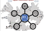
Transmission and Distribution protection and control schemes used by Eskom, the state-owned electric utility in South Africa, have been standardized for over 30 years. This article describes standardization philosophies applied to PAC schemes since 2000, with specific focus on changes introduced since 2015 which were bought about through the widespread adoption of IEC 61850.
Historical Standardization in the Eskom Wires Business
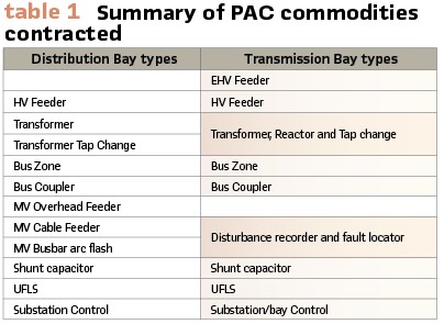
Standardization of PAC schemes between 2000 and 2015 was achieved through the establishment of supply contracts with local engineering companies for the design, testing and supply of PAC equipment specified at bay level for protection and bay/substation level for telecontrol. Contracts were established over four or five year terms and allowed for draw-downs based on project requirements over the contract period. The philosophy was to award one contract to a single supplier for each commodity type following an open tender process. (Table 1).
The tender process and prototype development phases typically took 1 year for simpler distribution schemes, and 2 years for more complicated ones, notably HV feeder and Transformer protection. The time was evenly split between the tender evaluation/award and the detailed design and prototyping of the solutions. Transmission commodities typically took 6 months for the tender phase and one to two years for detailed design and prototyping.
The historical approach to PAC technology direction setting had been one of incremental improvement. Improvements were almost exclusively implemented upon establishment of a new supply contract. An effort was made to implement similar improvements across all product ranges. The staggered nature of the scheme contracting periods, with contracts for different commodities mostly running over different periods (limiting the development burden on Eskom to a few schemes at a time) meant that there were often periods where existing and improved scheme technologies for different bay types would need to be applied together at one substation.
Why Standardization?
The objective of standardized PAC schemes is to meet the requirements of different substation bay types in an optimal (minimal) number of hardware and software variants so as to:
- Maximize on economy of scale both in procurement and operation and maintenance of technology; and
- Minimize technology “churn” whereby staff need to learn and support both multiple generations of technology and multiple product variants within each technology era
What is Standardized?
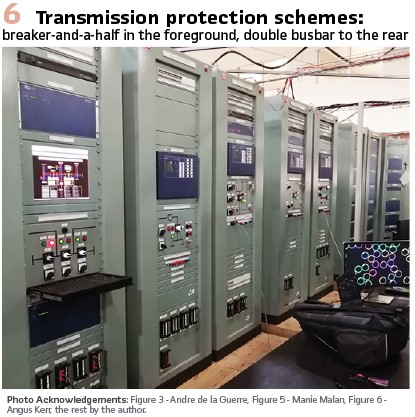
Standardized protection schemes include a suite of major variants to cover major application options, for example breaker-and-a-half vs double busbar substation configurations, or HV feeders for single and three pole tripping or three pole tripping only. For each major variant, minor variations are addressed by ordering options which are presented as levels/layers on the CAD drawings. Different teleprotection communication options, or optional voltage selection relays are examples of such minor variants.
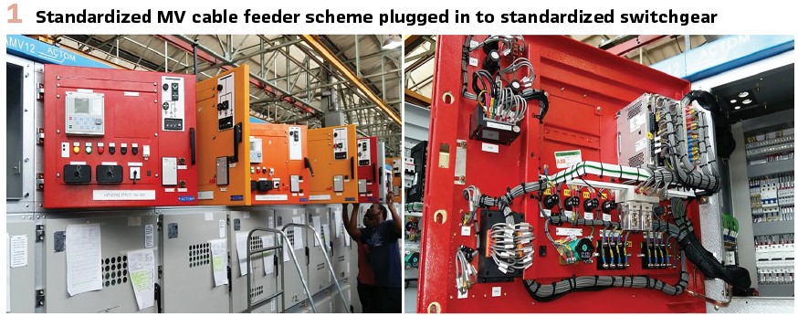
Within the Distribution environment where significantly higher volumes of protection schemes are applied, the interface with primary plant equipment has been standardized. Terminal and ferrule numbers of secondary plant connections are standardized across all plant of the same type: circuit-breakers, disconnectors, power transformers etc. Protection scheme master drawings are thus able to include detailed wiring diagrams and cabling schedules for the application of the schemes in typical projects. (see Figure 1).
Standardized protection schemes attempt to limit the number of different IED hardware options applied, limiting spares holding requirements. Limiting IED hardware variations enables the establishment of standardized settings templates. Protection settings are managed using Microsoft Excel including the facility, via Visual Basic macros, to export IED settings in a file format suitable for direct import into the IED’s setting software.
A design freeze is applied to all standardized schemes following completion of factory acceptance testing, with the physical design and IED hardware, firmware and configurations being maintained on fixed versions. Subsequent firmware or software releases by the OEM are only implemented in the event that they correct a notable defect, or should they introduce a significant new feature.
IEC 61850 Adoption Brings a New Standardization Approach
A 2013 technology direction setting project identified opportunities for business improvement through the implementation of new technology. Foremost of these for the Transmission business was the need to improve the sustainability of substation refurbishment. Historical bay-level protection schemes are wired in a one-to-one relationship with primary equipment and rely on extensive copper cabling between the substation control room and the primary equipment. Protection scheme refurbishment required long bay outages which were not always feasible in a constrained power system, and which meant that refurbishment was occurring at a slower rate than required. In the new generation protection schemes it was envisaged to:
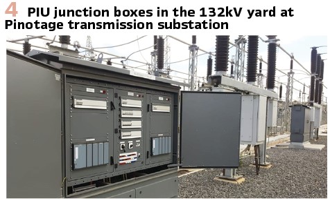
1. Split the protection IEDs, applying “Process Interface Unit” (PIU) IEDs in junction boxes within the substation yard. The main processing for protection and control functions was still to be undertaken by control room-based IEDs. Communication between the control room IEDs and PIUs was to be via IEC 61850 GOOSE. This design feature allowed for copper signaling cables to the substation yard to be replaced with a single fiber optic cable pair per main. Analogue signaling to the protective IEDs was to be retained as conventional (not using Sampled Measured Values)
2. Split dual main schemes into two fully redundant single main schemes. Applications with dual main protection were to have the control room-based panels split into two fully redundant, independent panels. This approach is made possible by the fact that the control building interface to the bay’s primary plant is achieved predominantly via a fiber optic link. The telecontrol interface, formerly undertaken by a discrete Bay Control Device (BCD), was now to be achieved by each main protection IED using IEC 61850 MMS. The new designs make it possible for a complete main protection system to be removed from service for fault finding, repair or complete replacement whilst the primary plant remains in service with full protection and control capability provided via the second main
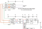
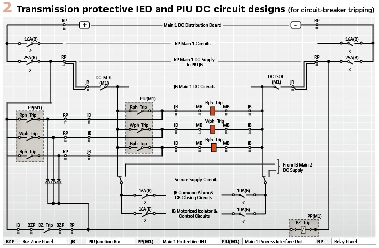
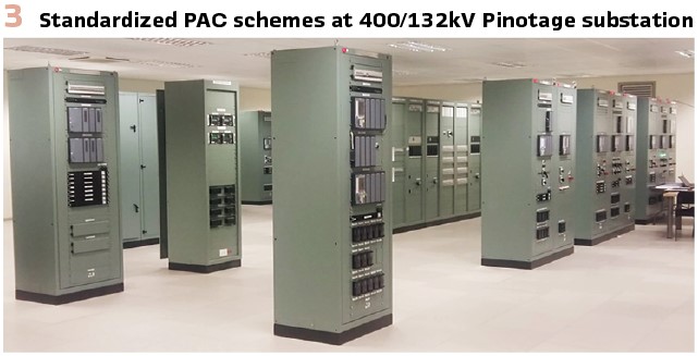
In the final Transmission designs, the PIU junction box was segregated into Main 1, Main 2 and Common areas. Figure 2 is a summary of the DC circuitry of the Main 1 and Common areas, the Main 2 area being a copy of Main 1. The original design was for protection and control tripping only via GOOSE from the Main 1 IED (PP(M1)) to its PIU (PIU(M1)), with the bus zone trip being hardwired from the relay panel to the junction box, tripping the circuit-breaker tripping coils directly. This was later adapted to include hardwired protection tripping from the main IEDs directly to the circuit-breaker tripping coils. This modification was implemented as a dependability improvement, recognizing that the tripping wires to the junction box were already existent, and spare trip-rated output contacts were available on the main IEDs. With one OEM, the availability of solid-state output contacts on both the main IEDs and PIUs meant a marginal speed improvement with hardwired tripping from the main IEDs. It was reasoned that it would be simple to remove or not apply the hardwired trips in future applications, but that they would be difficult to retrofit to a design that omitted them. (Figures 3/4).
Local operating at Transmission and larger Distribution substations is to be undertaken via a substation HMI, including interlocking to reduce operating errors and to improve local situational awareness. Redundant gateways and substation HMIs are applied in Transmission substations in an active/hot stand-by arrangement.
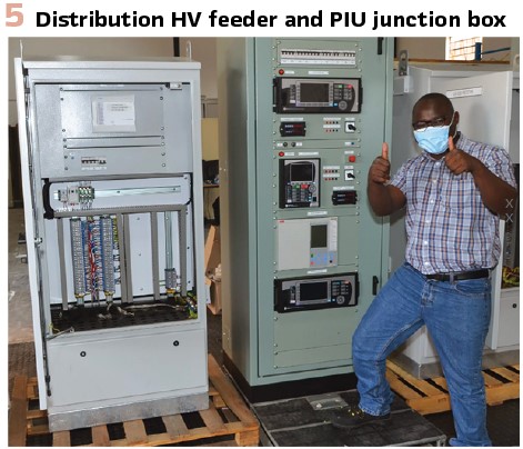
The technology direction for the Distribution business is to use PIU devices in the substation yard to interface with the main protection IEDs of HV feeder and Transformer bays and for the tap change scheme, but that back-up IEDs would retain their conventional hardwired I/O with a limited signal set. MV-level schemes are to retain their traditional hardwired interface to the primary plant for all signals – the small number of signals not justifying the application of a PIU.
The motivation for PIU devices at Distribution substations is to avoid the theft risk of copper cabling in the substation yard, and to cater for increased signaling requirements for motorized isolator and earth switches as provided on modern hybrid primary switchgear.
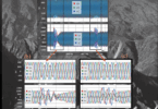
The Distribution HV feeder scheme in Figure 5 includes (from the top) main and back-up protection modules and allows for the integration of a third-party Line differential IED so as to achieve interoperability with the IED type at the remote line end. The prototype panel included a second main IED to allow for end-to-end testing during the factory acceptance testing (FAT.)
The commercial strategy to implement the new technology direction was chosen as integrated PAC contracts comprising all of the main protection schemes, Ethernet networking and time synchronization devices, and substation gateways and HMIs. Separate enquiries were issued for Transmission level equipment (88kV and higher voltages) and Distribution level equipment (132kV and below).
Two contracts were awarded from each enquiry. The integrated solutions included all protection schemes previously contracted, excluding the disturbance recorder/fault locator, and shunt capacitor and Under Frequency Load Shedding schemes, which were retained as stand-alone contracts to be awarded to one supplier each, catering for both Transmission and Distribution. There were three main reasons for the change in contracting philosophy to a single PAC equipment supplier per substation:
1) Reduction in interoperability risks. With widespread application of IEC 61850 being new to the business, it was felt prudent to limit interoperability risks by allowing for the majority of core commodity IEDs to be supplied by the same OEM
2) Need for a system integrator. The new-generation secondary plant schemes would require application-specific engineering, especially in their interface to the substation gateway and HMI, and it was felt important that this be done in a factory/laboratory environment and not on site
3) Establish the most common substation bay types simultaneously on the new design philosophy
A secondary benefit of the new contracting approach was to encourage the standardization of the same IED hardware platforms across multiple commodities, with significant benefits in staff training, and software and spares support.
Experiences in implementing the new technology direction and commercial approach
Eskom ran separate commercial processes for the establishment of supply contracts for the integrated PAC solutions for Transmission (2014 – 2019) and Distribution voltage levels (2016-2021). This section describes some of the key learnings from these projects:
Success factors:
1. Specification approach based on the structure of IEC 62271: High-voltage switchgear and control gear
The integrated solutions each included multiple different protection scheme types, with individual commodity specifications such as HV feeder protection, Transformer protection etc. being compiled by different engineers. It was important that a framework be established under which the individual commodities could be specified yet maintaining uniformity in common aspects between schemes. It was observed that the IEC 62271 series of standards on HV switchgear addressed a similar problem in an elegant manner.
IEC 62271 Part 1: “Common specifications” describes aspects which are applicable to most or all switchgear. Each specific type of switchgear is described in a separate part of the standard. In all cases the detailed type-specific standards follow exactly the same heading structure as does the Part 1 standard. Each type-specific standard then re-affirms or modifies the requirements of Part 1.
The “Common requirements” specification for Eskom protection schemes detailed aspects such as:
- Variant naming
- Scheme interfaces: DC and AC supply ranges and CT and VT circuit ratings and design
- Generic performance requirements
- Physical construction
- Requirements for common protection, control and measurement functions/logical nodes
- Descriptions of common/historical design elements and alarms
- Testing requirements
- Development process to be followed
- Documentation and training requirements
A second common specification was compiled detailing generic requirements for IEDs, including ratings, functional requirements and type tests, in accordance with the IEC 60255 series of standards.
2. System homogeneity scoring factor on tenders
Ten percent of the total technical evaluation score on tenders was affected by the homogeneity of the offered solution. Homogeneity was determined by the number of different IED families that were offered to meet the protection scope, including control-room installed IEDs and PIUs.
3. Follow a structured, defined design process
The development of telecontrol commodities had historically followed a formal, structured process. This was expanded to protection commodities and included three phases:
- Functional design specification. For this milestone, the supplier re-affirms their undertaking to meet the requirements of the utility’s specifications, restating the requirements in terms of the products offered. This step is intended to ensure that the supplier’s and utility’s design staff are familiar with the requirements to be met, specifically as different personnel may have been involved with the project at tender stage
- System design specification. Definition of the physical, logical, and communication interfaces between commodities as well as the human machine interface. This stage also considered design elements that were applicable across commodities such as grouped alarms, testing facilities and trip circuit design and supervision to ensure that these elements were applied consistently across all commodities. Once the first-pass IED configurations had been completed per commodity, spreadsheets were used to ensure consistent usage of common design elements such as IED LEDs/annunciators and disturbance recorder channel allocations. A similar comparison exercise was undertaken between commodity IO lists
- Detailed design specification. Detailed design drawings and IED configurations for each commodity
4. Standalone testing of IED platforms prior to scheme construction
Model power system simulator testing was undertaken on the Line distance/differential and transformer protection IEDs and PIUs for the Transmission-level commodities. This allowed for performance verification of the IEDs at a relatively early stage in the development project and provided hands-on exposure to the IEDs in action well before the complete schemes were manufactured for FAT.
One of the distribution-level contracts used the concept of “IED FATs” to bench test common IED features months before the commodity FAT on the complete protection schemes. Doing so helped to clarify understanding of the operation of the IED (this being valuable when IED configurations needed to be developed and checked), and in some cases identified shortcomings in the IED firmware that could then be rectified without negatively impacting the overall project schedule.
Challenges: The following challenges were experienced in executing the integrated PAC development contracts:
1. Increased scope and value of contracts complicates budgeting and governance approvals
Evaluation and awarding of contacts for the integrated solutions took 60% longer than previous developments. This statement is made referring to individual commodity developments being undertaken in smaller packages (for example groups of three Distribution commodities at a time).
2. Difficulty in maintaining design homogeneity with different engineering leads assigned per commodity
This applied to engineers from both from the utility and supplier. It is important to ensure that all personnel maintain a “system view” of the solution so as not to introduce unnecessary variations in designs between commodities.
3. Completion only achieved with the last commodity, delaying deployment of developed solutions
There was frustration amongst management and engineers at the development contract duration, and that no part of the solution could be implemented prior to completion of all development work. Users of the technology have also had to adjust to being presented with a completely new solution at once.
Looking Forward: Adoption of Sampled Measured Values
The new-generation protection schemes for the Eskom wires business retain conventional analogue input circuits: 1A CTs and 110V VT circuits wired to the control room-installed protective IEDs. The Transmission business is exploring options to implement Sampled Measured Values (SMV) to the IEC 61869 standard at a new-build gas-insulated substation. Such a project is anticipated to provide the opportunity to apply non-conventional instrument transformers as well as providing a vehicle to be able to adapt existing standardized protection schemes for SMV.
Eskom will evaluate SMV technology for mainstream application in standardized schemes in the following generation of PAC technology, expected to be available from 2027.
Conclusion
Development of the new-generation PAC schemes for the Eskom wires business including development of the technology direction and commercial strategy has taken eight years.
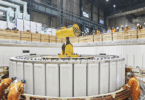
Two new-build Transmission substations have been commissioned using the new technology, and the sound of the transformer inrush was sweet reward. We look forward to many more such events as the new technology gets deployed in projects across South Africa. The following are some take-home points:
- The use of standardized schemes and standardized IEDs reduced the amount of learning required in terms of settings, commissioning and maintenance
- It is critical to maintain a system view when developing integrated PAC solutions, to facilitate interoperability and to maintain homogeneity
- Different suppliers have different IEC 61850 application approaches which become barriers to interoperability between solutions. Eskom has addressed this by using one supplier per substation where possible
- The application of Process Interface Unit (PIU) devices close to the primary plant equipment significantly reduces cabling between the substation yard and the control room, but proved more expensive than traditional copper cabling
Biography:

Stuart van Zyl is a Chief Engineer, power system protection from Eskom Transmission. He holds a master’s degree in power engineering from the University of Cape Town and is actively involved in PAC scheme standardization for Eskom’s Transmission and Distribution divisions, having fulfilled roles of technical supervisor and project manager on recent development contracts.