by Walter Schossig, Germany, and Thomas Schossig, OMICRON electronics GmbH, Austria
The last issues covered the history of relay test sets. Now we are going to continue on testing guidelines and technology. Electrical engineers started developing guidelines and testing recommendations early on.
In Germany the first association of electrical engineers – the VDE (“Verband Deutscher Elektrotechniker”) – was founded in 1893. They immediately started working on “Technical rules for the erection and operation of electrical power plants”. The part on operation was first published in 1903. Georg Dettmar published his “Advice book for operation and maintenance of power plants” in 1903 and later in 1928. He writes:
“The purpose of all guidelines should be the creation of safety – for the people in the substation as well for those in contact with it. Additionally, it is important to be safe in case of fire and to guarantee the reliability of operation. Everyone who erects such plants is respnsible for taking into account the applicable technical rules. This means especially the erection rules published by VDE, as well as the operational rules. He is responsible for fulfilling the rules. If this is true, his responsibility in case of an accident or in case of fire will be limited, since this is recognized as an act of nature beyond control.”
First Rules on Protection and Control
In 1910, the “Guidelines on standardized erection of trainings for electrical technicians and guards of electrical plants” were published. The goal was explaining to the colleagues how important safety is and to allow proper operation. Additionally, it should increase the joy of work and explain the application of measurement and test equipment. So, the first safety regulation was published in Germany in 1895 as a predecessor of the well-known VDE 0100:
“The main switchboards in operating rooms shall consist of noncombustible material. All current-carrying parts have to be mounted isolated and on a fireproof base.”
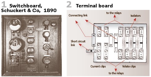
At the beginning of heavy current engineering (1880/90) the “switchgear” consisted of the DC generator (“dynamo machine”) and its control on a board (made of planks). On the top there were current carrying parts directly on the board. This was the main switch and -if available- the main fuse. Wood was known as a good isolation material at this time. Later this arrangement was extended by the measurement and protection equipment. Figure 1 shows a typical board. The planks are visible, and the setup was DC distribution board for a generator by Schuckert & Co in 1890. The most important testing at this time was the isolation test. Due to fire protection, those boards were changed to marble boards (Figure 3).
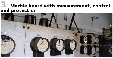
Figure 4 shows an insulation tester for AC systems. It was introduced by Wilkens and Benischke, AEG, in 1899. To measure resistances up to 1Ω required high sensitivity. This was achieved by an induction measurement element, working like a separately excited dynamometer.
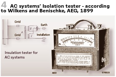
A magnet system was powered via transformer by the grid, also delivering measuring voltage.
To detect failures the Austrian magazine on electrical engineering and engine construction recommended: The supervision and maintenance of the protection system shall be done by a special team, consisting of at least two persons. They have to test all relays, all measurement transformers and their corresponding interaction. To do so a special current transformer shall be used (relay test set). Since neither the measurement transformer, nor the relay, nor the connections show if there is a problem and the entire systems shows its performance only in case of fault, there is no regular check between the periodic tests (which are recommended at least once per year). So, there is no trust in that the relays work properly. It is not enough to know, that the last test went well. This uncertainty is the main weakness of protection. To overcome it is necessary that the system shows proper working not just in case of failure, but also during normal operation. There are several variants to do so:
Equip the relay to work as measurement devices, as volt meters, ampere meters, impedance meters and thermometers. The pointer must indicate a defined value as on the switchboard. If this is true, current and voltage transformer connections work properly and are connected to the relay. If something is missing, this indicates failure in one of the parts. This approach allows supervision of the entire AC system
Use glow lamps or lamps in general and switch them in parallel to the trip contacts. If the current is below the startup value of the relay the lamps are on and indicate proper connection of coil and contact. A case of a double earth fault on the relay contacts may cause a false tripping in case of higher currents. This method does not check the trip contacts directly. It does also not check the coil or if there is short circuit on the line. Even if this happens seldom, the method below shall be used
A test switch shall be available at the relay which closes the contacts at the relay. In case of over voltage relay the series, resistance shall be short circuited. If the oil switch cannot be idled, it has to be blocked. Since this shall not be forgotten, a clear mark is mandatory
These tests can be performed weekly or even every time at a round tour of the person in the substation.
Troubleshooting or testing required opening the wiring. To do this conveniently, “terminal boards” were introduced. These predecessors of the series terminals as known today were introduced in 1926. Opening was done as before by disconnecting the wires- which was still time-consuming and included the risk of confounding. (Figure 2).
First Rules on Testing of Protection and Control
The German VDE published “Provisional Guidelines on Construction and Testing of AC High Voltage Apparati for Voltages Above 1500 V for Indoor Application” in 1912 („Vorläufige Richtlinien für die Konstruktion und Prüfung von Wechselstrom-Hochspannungsapparaten von einschließlich 1500 V Nennspannung aufwärts für Innenräume, R.E.H.“) Additionally, they published “Regulations on Construction and Testing of Isolation Material” in 1928 („Vorschriften für die Konstruktion und Prüfung von Installationsmaterial, K.P.I.“) An additional document was describing the application of switchgear in 1928 (“Regeln für die Konstruktion, Prüfung und Verwendung von Schaltgeräten bis 500 V Wechselspannung und 3000 V Gleichspannung, R.E.S.“)
These are the rules:
Electromagnetic tripping must apply as follows:
1. Overcurrent trip. The setting range of the devices for the fast trip has to be in the range of 1…2 times of nominal value. Delayed stages have to be reset without tripping if the current reduces to nominal value within ⅔ of the time set. The tolerance of the current must be within ±7,5%.
2. Undercurrent trip must work at maximum 10% of nominal current. In case of power-on they have to be stable at 15% of the nominal current
3. Reverse current tripping must be possible at 10% of nominal value
4. Decrease of voltage trip: They have to be stable during switching on, also if the voltage is only 70% of the nominal value. Tripping if the voltage decreases below 36%.
5. Switches to switch on still have to be operated in case of voltages in the range of ±10%
6. Switches to switch off must operate at voltage range +10% or -25%
The rules for the high voltage apparatus (R.E.H.) also shall be described:
Primary tripping device range 1.4..2 of nominal value:
- Time can be set
- Time range 8 s (±0,5s) and > 8 s (±1s).
- Reset within 1/2 of time set, if the current is back to nominal value
- Secondary relays shall display current set and time
- Error current max. 5% of value
- Error time ±0,4 s.
Secondary relays shall reset if the current is below 75% within 2/3 of time set.
It was required to check the relays permanently. They had to look well, work without blocking and should not show rust. This required grease. In case of short circuits, the contacts could burn and stick together. The time setting must be checked from time to time. Mechanical issues might harm the proper operation of the relay. That’s why the relays should be clean and protected against dust. Testing of the trip circuit should not be done manually, but through the relay trip output.
Examples for Testing of First Protection Relays
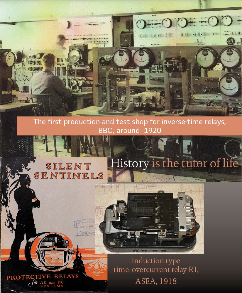
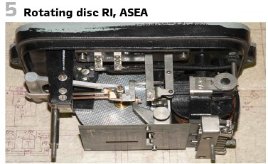
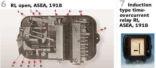
The RI relay (Figure 7) is perhaps the most well-known relay of this era. It was developed in 1918 by the famous designer, W. H. Petersén, and included a special contact switching feature. This relay was delivered to a considerable number of countries worldwide between 1920 and 1985. Although the last RI unit was produced in the 1980s, this relay is still used in many countries. This relay marks the first electrical boom in Sweden and is an excellent example of a successful product with an extremely long-life span. In fact, the same inverse time-overcurrent curve is still implemented in modern numerical relays to achieve time coordination. RI was the first relay to utilize high-speed resetting after trip operation, which allowed high-speed reclosing.
One of the most remarkable features was the permanent supervision, since the rotating disk already rotated at small currents. False trips due to leakage rotations could be avoided by a special stabilization mechanism. The timing element was decoupled and only connected if the current reached defined value. Also, the reset value was 85%.
To explain the testing efforts, some technical details shall be explained.
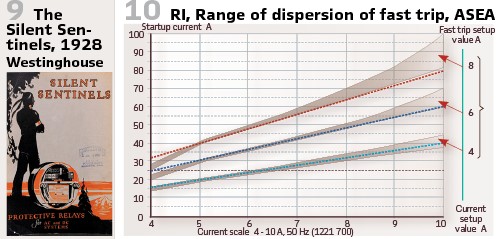
As mentioned, the relay indicates proper operation via a rotating disc (Figure 5). Startup and trip are indicated. To set up the starting value, the spike p can be moved (Figure 6). This switches the number of windings. If the spike is removed, the maximum starting value is chosen automatically. This allows setting up value without opening the CT circuit. The time can be set via adjusting screw t. To achieve fast tripping, the adjusting screw m has to be moved. This decreases the air gap of the tripping anchor. The visualization is realized via yellow and red indications. They can be reset and fixed for transport (Figure 6). To test the fast trip at 4, 6, and 8 times the setting value the vendor delivers characteristics with variations (± 2% of time, ±1% of maximum scale, Figure 10).
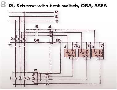
Checking the manual of RI:”Under normal conditions it is sufficient to grease the bracket every second year. No further maintenance is needed. If the air contains dust or aggressive gases and in case of high humidity there shall be additional checks. Dust must be avoided; the relay shall be protected with caps. All parts are moveable for greasing. ASEA delivered special oil. The rotating disc indicates proper operation, nevertheless starting value and time shall be tested regularly several times per year. For easy testing ASEA relay test switch 4 (type OBA, Figure 8) was available.
CT circuits and tripping were disconnected. An additional relay testing apparatus R Il was available to inject currents, voltages and measure the time. Comparing the testing results at several times made it possible to decide if next revision is required. At the factory the relay is calibrated in that manner, that the times are perfect at 3 times the defined current.
In case of overload the contacts might be rough. So, rasps shall be used, sandpaper is not recommended since something can fall into the mechanical system.
The Demand for Delayed Trip
Oil breakers have been a huge problem. To us it may sound crazy today- but in 1919 it was the rule, that there shall be a delay of 1 sec to have reduced short circuit current and preserve the breaker. Reading the announcements of the German Association of Utilities (Vereinigung der Elektrizitätswerke Nr. 276) 1920: “In case of line fault (earth fault or short circuit) the delay shall be set to at least 0,75 to 1 second considering the immediate short circuit current. The tripping device shall be ‘woke up’ as we say.”
First Testing Procedures
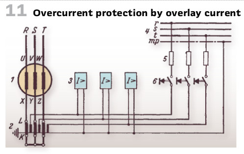
Figure11 shows simple test procedure with overlay current for 3 overcurrent relays. The test push button 6 is used to add overlay current to the operating current. The value can be changes via the resistance 5. Pushing the button delivers the current. Via the testing resistance this can be increased. To avoid tripping those connections the de-excitation switch will be interrupted. Additional measurement devices and controllers make it possible to check the starting value of current as well as the delay without additional reconnection.
Westinghouse published a very nice relay handbook with the title “Silent Sentinels” in 1928 (Figure 9):
“Relays have been aptly termed “silent sentinels.” And they are silent sentinels. They stand on ·duty twenty-four hours a day, every day in the year, and-year in and year out. They guard thousands of dollars’ worth of property and equipment. They prevent service interruptions and costly shutdowns. They are really and truly the silent sentinels of the electrical industry. Automatic control is a reality. Supervisory control has been introduced. The interconnection of systems is no longer an experiment. Service is now reliable and continuous. All of these are attributes of super-power-a new era in the electrical industry.”
The book covers all kind of protection for AC and DC systems and testing is not the main topic.
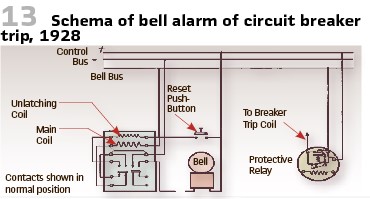
Nevertheless, the book describes methods of applying relays to circuit breakers. An audible signal of some kind is usually provided to sound whenever a breaker tripped automatically. A common method of accomplishing this is to provide a separate bell bus on one side of the control circuit and interpose a series signal relay between this bus and the source of supply (Figure 13).
Additionally, “Portable Phase Indicator” for use in making relay connections was recommended. In order to obtain correct operation when connecting a relay, which requires both current and voltage connections, to a polyphase circuit, it is necessary to select the current and voltage having the proper phase relation to each other. One of the most convenient methods of checking such relay connections was to use a ‘Westinghouse Phase Indicator”. The phase indicator shown in Figure 15 is a portable instrument built on the same principle as is a power factor meter. However, the phase indicator is calibrated to indicate degrees, from 0 to 360, instead of power factor percentages. It readily shows the exact phase relation between any current and voltage to which it may be connected.
The phase indicator can also be used to check the phase relation between two or more currents. An example of such an application is the checking of relay connections for differential protection. To select the two current transformers the secondaries of which should be connected together, it is necessary only to select some voltage for use as a reference, and then to measure the phase relation of the different currents with respect to this reference voltage.
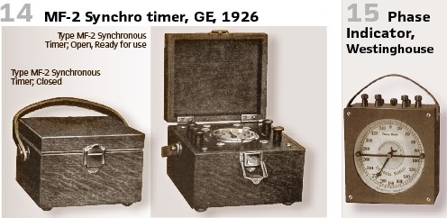
The National Electric Light Association published their relay handbook in 1926. It covers the state of the art of protection, AC and DC relays, circuit breaker tripping, current and potential transformers as well as testing. The General Electric synchronous timer type MF-2 was covered. The device is for indicating accurately the time required for a relay or other device to operate. It was used for making periodic and other tests especially where precise timing is essential.
The timer is for use on a 110-volt 50-or-60-cycle circuit. It consisted of a miniature synchronous motor , geared through an electrically operated friction clutch to drive two dial pointers or hands, one of which rotated 12 times as fast as the other. These hands are started and stopped by means of the clutch. A knob is for resetting. The dial, with the two hands, looked exactly like a clock face (Figure 14).
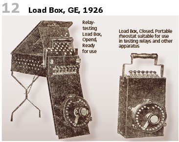
Also, by GE is the “Load Box”. Easily portable it was intended for connection in series with the current winding of a current or power relay, to adjust to various desired test values the current obtained from a constant potential AC or DC source (Figure 12).
Already in 1919 Woodrow,H.R.; Roper,D.W.; Traver,O.C.; Macgahan,P. presented a general paper on “Transmission Line Relay Protection” at the 35th Annual Convention of the American Institute of Electrical Engineers at the Lake Placid Club in New York. On 32 pages the state of the art on transmission line protection is described. One chapter covers testing and setting of relays.
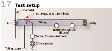
“In order to secure the best results from the relays, it is desirable to make a complete check on the current and time settings of each relay on the first installation and at least once every six months thereafter. Although the time for making these tests is determined to a large extent by the operating conditions, we feel that the best results will be obtained if a general plan is worked out for performing these tests at regular intervals. If selective operation is to be obtained from the relays the greatest care and precautions must be taken in making these tests. The tests should be performed under conditions as nearly equal to the operating conditions is possible which makes it desirable to include the wiring and complete relay equipment in this test. In this test, wherever practicable, the test current should be applied to the primary of the current transformer. Where it is impracticable to do this the testing current may be supplied to the secondary terminals of the current transformer with the current transformer left in circuit as a shunt as shown in Figure 17.
The results obtained under these conditions very closely approximate those under short circuit and check the relay wiring and current transformer, as well as the relay. This will detect any short circuit in the current transformer or wiring and any open circuit in the wiring but open circuits in the transformer coils should be determined by a separate continuity test. The degree of accuracy obtained when the relay is tested alone is dependent upon the type of transformer used and the secondary load. The error in this method is due to the high magnetizing current of transformers (especially with the low ratio single turn type on heavy secondary loading) on the heavy short-circuit conditions. As an example, a 40-volt ampere secondary load on a current transformer at full load imposes a 16 kVA load under short-circuit conditions of twenty times full load. This, in many cases, is above the saturating point of the transformer and the ratio breaks down badly.
The time-current curve of a relay is affected by the nature of the secondary load or by the current transformer characteristics. It is therefore desirable to test each individual relay with current such as would be occasioned by short circuit. At least three points along the curve should be taken, one of which is approximately 150 per cent of the minimum value, one at as near maximum short-circuit current as the testing equipment will permit, and one intermediate point. The time should be taken by a chronometer or cycle counter which will eliminate the personal equation of the operator. The method of timing by a stopwatch is entirely inadequate for close relay settings. An additional inspection should be made about every month for continuity of trip circuits (where this is not indicated by lamps) and for dirt or mechanical defects, and where conditions will permit, the relay should be operated to trip the circuit breaker. In case of bellows relays the bellows should be oiled with oil to prevent hardening.”
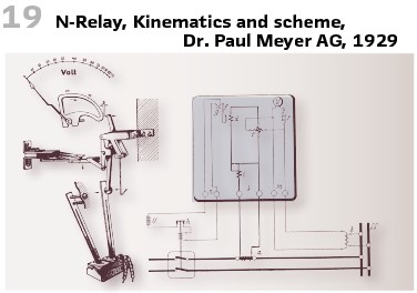
For exposed stations it was common praxis in the US to check the relays daily. They even measured the pressure on the contacts with special trolleys. The N-Relay was widely used in the late 1920s (Figure 19).
For the proper operation of the selective protection exact calibration was essential as well as uniformity of the relays.
So, in the testing room of Dr. Paul Mayer AG 12 relays have been calibrated simultaneously and compared to the comparison standard (Figure 20). At first the voltage scale was calibrated. After this the voltage was kept stable and current was injected. On a large registration drum rotating with high speed all tripping times have been recorded.
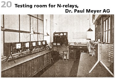
On the drum’s perimeter one mm is equal to 0.05 seconds- so all deviations could be found. After this the voltage discs could be justified until the difference was less than ±0.1 s. The time was measured by a special recorder, consisting of a paper drum and working like a typewriter. Every trip printed a dot. When all 12 points have been on single line, calibration was finished. If 1 mm of drum’s perimeter was equal to 1/20 s , high accuracy could be achieved (±1/5 … 1/10 s).
Testing of generator protection was another topic. Figure 18 shows an example. To test the protection test button (7) was used. The auxiliary source is disconnected from tripping device and switched to lamp (20), bell (19) indicating proper operation. The winding protection is a differential protection. The CTs with 5A nominal current are connected to the relays (12). The relays are set to 1A, so they trip at differential current of 20% of nominal current. For the test of the relays (12) the buttons are prepared (18e, 18f and 18g). They deliver the current from the reactor coil (4) via resistances (22). In case of trestle fault the current flows from the faulty winding to earth and voltage transformer in neutral point back to generator. The capacitive earth fault current flows to earth and pushes currents through CT. They do compensate in the earth fault relay. If there is an excitation at the same time of the voltage coil, the earth fault relay starts up. Pressing the button 7a tests the earth fault relay.
So, in the 1920s it was well accepted by most utilities that maintenance of the relays was essential for the reliability of the grid. Specialists were hired, that were responsible for the relays. The most important was checking the tripping circuits, including the couplings to the oil breakers (Figure 16). Times and characteristics have been tested, as well as the kinematics of the single elements and the entire relays. Recalibrations could be done on site with special equipment, this was seldom done in relay or meter labs (Figure 20).
At the end, a special test was switching on oil breakers. They watched the relays at this time. If something in the relay “floundered”, they had the info that the relay works properly.
In the next article we will talk about short circuit trials and grid models.
walter.schossig@pacw.org www.walter-schossig.de
thomas.schossig@omicronenergy.com
Biographies:

Walter Schossig (VDE) was born in Arnsdorf (now Czech Republic) in 1941. He studied electrical engineering in Zittau (Germany), and joined a utility in the former Eastern Germany. After the German reunion the utility was renamed as TEAG, Thueringer Energie AG in Erfurt. There he received his master’s degree and worked as a protection engineer until his retirement. He was a member of many study groups and associations. He is an active member of the working group “Medium Voltage Relaying” at the German VDE. He is the author of several papers, guidelines and the book “Netzschutztechnik [Power System Protection].” He works on a chronicle about the history of electricity supply, with emphasis on protection and control.

Thomas Schossig (IEEE) received his master’s degree in Electrical Engineering at the Technical University of Ilmenau (Germany) in 1998. He worked as a project engineer for control systems and as a team leader for protective relaying at VA TECH SAT in Germany from 1998 until 2005.
In 2006 he joined OMICRON as a product manager for substation communication products. He is author of several papers and a member of standardization WGs.