by Jonas Pesente, Robson de Oliveira, Andre Tochetto, and Alfredo Mezger, Itaipu Power Plant, Brazil, Gustavo Aguayo and Elisandro Rodríguez, ANDE, Paraguay, and Christian Romeis, Siemens PTI, Germany
Higher demand of power supply and power system stability requirements are steadily imposing innovative solutions based on Wide Area Monitoring equipment such as PMUs (Phasor Measurement Units), since traditional operation systems might not react properly on critical contingencies in the power system. Therefore, the monitoring system is extended with protection and control capabilities, resulting in a Wide Area Monitoring, Protection, Automation and Control system (WAMPAC).
The goal of such a system is to secure and observe operation in normal conditions, and in case of contingencies which could bring the network to the brink of instability, the WAMPAC system automatically initiates actions on the grid. These actions can range from controlling generators, opening interconnectors to load shedding.
ANDE, the state-owned electricity utility from Paraguay, in partnership with ITAIPU BINACIONAL (ITAIPU), and ENTIDAD BINACIONAL YACYRETA (EBY) designed such a WAMPAC system (Esquema de Control ante Contingencias de Ande = ECCANDE), to ensure a secure and reliable interconnection between ITAIPU hydro power plant (to Brazil) and YACYRETA hydro power plant (to Argentina) through ANDE’s power system. The interconnection is performed via 500 kV and 220 kV transmission lines, tying together two subsystems which operated separately until now. The WAMPAC system was developed, tested, and commissioned together with SIEMENS.
ECCANDE WAMPAC System
Upon the detection of a severe contingency in the system, the ECCANDE system performs basically two main actions: it splits back the two subsystems, and it activates a set of undervoltage and underfrequency load shedding schemes. This WAMPAC-system was designed to act with 4 logics for internal contingencies associated to transmission line openings within ANDE’s power system, 3 logics for external contingencies, associated to voltage angle differences and active power flows in the system and a direct transfer trip (from ITAIPU). Each contingency leads to a different reaction in the power system, and depending on the topology and the magnitudes, the ECCANDE will actuate. The ECCANDE system is very complex because various PMUs are used to monitor the condition of the system. In sum 16 substations are involved in the 220 kV and 500 kV system.
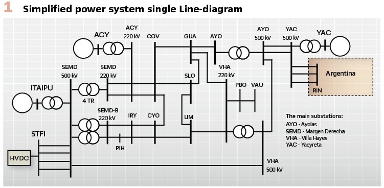
Figure 1 shows the simplified power system which was used to investigate the dynamic system behavior in case of interconnection and islanding conditions. The interconnection is done in the 500 kV level in substation Villa Hayes (VHA) and in 220 kV level in substation Guarambaré (GUA). The hydro power plant in Itaipu has 14 GW of installed power one part is 60Hz directly feeding to the Brazilian grid and the other part is 50Hz directly feeding to the ANDE power system. Between both parts a HVDC coupling is installed. The Yacyreta hydro power plant has a total power of 3 GW.
Based on a broad analysis of the power system with various load flow scenarios and dynamic simulations, logics were developed which ensure a secure power supply for ANDE’s power system in case of these contingencies. The logics have different input parameters which range from circuit breaker positions to phasor data and active power metering. The logics monitor the system configuration and decide whether the ECCANDE system is armed or not. The decision to trip the ECCANDE (and split back the system) is based on the detection of the outage of some critical 500 kV and 220 kV lines, on active power flow between Paraguay and Argentina, and on the voltage angle difference between strategic busbars of ITAIPU plant and near YACYRETA plant, reflecting the actual interconnection between ITAIPU, YACYRETA and ANDE.
Depending on the pre-event load flow scenarios and/or blocking of PSS in ITAIPU power plant, load shedding may be initiated. As a result of these actions, the power system instabilities subside, and the resulting separated grid recovers.
Design and Engineering of ECCANDE
The ECCANDE system is made up of many different components such as PMUs, protection relays, automation, and communication equipment, monitoring and processing software. All different parts must be combined to fulfill the complex requirements of the abovementioned ECCANDE system. ANDE, in collaboration with ITAIPU and EBY, found a comprehensive solution together with SIEMENS. The design was made in close cooperation among all partners of this project. The monitoring, control and protection schemes were realized with SIPROTEC5 PMUs, SIGUARD PDP, and RTU A8000 in a complete redundant scheme.
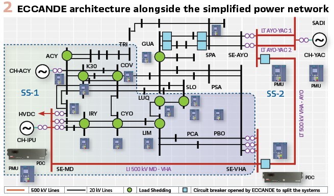
The overall architecture is shown in Figure 2 in conjunction with the simplified single line diagram of the network. The different building blocks are depicted, like PMUs, PDCs (Phasor Data Concentrators), and the substations where the load shedding will be initiated. The diagram also highlights the 6 circuit breakers that are closed during interconnected operation of both power subsystems (SS-1 and SS-2) and which are opened if a critical contingency is detected by the WAMPAC system. These logics will be described later.
The sensor building blocks are Phasor Measurement Units (PMUs) which make a valuable contribution to the dynamic monitoring of transient processes in electrical transmission and distribution systems. The advantage of PMUs over standard RMS values is for one thing that the phasor values of currents and voltages are transmitted, with their magnitude and angle. Secondly, each measured value includes the exact time stamp and therefore is assigned within the transmission path in which it originates independent of the time delay. The phasors and analog values are transmitted by the PMU with a configurable reporting rate. Due to the high-precision time synchronization (via GPS), the measured values from different substations that are far away from each other can be compared, and conclusions about the system state and dynamic events, such as power flow, can be drawn from the phase angles and dynamic curves.
The PMU function transmits its data via an integrated Ethernet module using a standardized IEEE C37.118 protocol. The evaluation can be done with a Wide Area Monitoring System e.g, with SIGUARD PDP (Phasor Data Processor). The time of the PMUs must be synchronized via GPS with an accuracy of < 5 µs. This enables the PMUs to acquire the measured values with amplitude and phase as phasors (synchrophasor values) with high precision and to transmit them via the communication interface. These PMUs are connected to the current and voltage transformers.
For the central intelligence and data processing the SIGUARD PDP (Phasor Data Processing) is used. This is a software for monitoring the status of power transmission in extensive power systems. When critical states are approached e.g. frequency, voltage or angle stability and power swings, this condition is detected early and displayed.
The thresholds at which a critical state is reached and requires interventions can be defined and subsequently changed at any time.
It also works together with PMUs (Phasor Measurement Units) as a PDC. The time-synchronized measured values from regionally widely distributed measuring points can be collected and evaluated.
The ECCANDE system receives information from 16 substations, depending on the location and their configuration in the system, the architecture of each substation is different. The project was designed with three types of communication architectures:
- Substations with high relevance with PDC server
- Substations with high relevance without PDC server
- Single substations, where the load is typically shed
In substations with high relevance for the system there are PMUs in redundant configuration (main& backup). These PMUs are collecting and sending the information by C37.118 to the redundant PDC servers, which receive the information from the PMUs of all substations. The PDC servers send the substation information, and the logic and system status to the RTUs by IEC 60870-5-104. The RTUs distribute the information sending GOOSE messages about the logic’s status and trips by IEC 61850 to the PMUs and sending substations and logic status to the HMI and Control centers of all three parties (ITAIPU, EBY and ANDE) by IEC 60870-5-104.
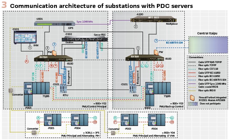
Figure 3 shows the communication architecture of substations with PDC servers. The purpose of this topology is to collect and transmit local measurements through redundant PMUs and to receive and send the information of the other substations using a Multiplexer, with a redundant connection to two communication switches. The GPS is used to synchronize PMUs using IRIG-B protocol, NTP protocol for computers, PDC and RTU, and a signal of 2,048 MHz for the Multiplexers network.
As stated before, this communication topology is redundant, having one PDC in substation Villa Hayes (VHA) and the other one in substation Margen Derecha (SEMD), at Itaipú power plant. Both PDCs operate in a Hot-hot configuration.
The communication architecture for single substations is much simpler. Its topology considers only one PMU connected directly to the Multiplexer, and a GPS for the time synchronization by IRIG-B. The PMU sends the information by C37.118 and receives data by IEC 61850. This topology is employed mainly at the load-shedding substations.
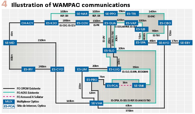
A dedicated and redundant MPLS communications network, built upon OPGW and ADSS fiber optics, is implemented throughout the country, linked by 23 multiplexers, using the C37.118, IEC 60870-5-104 and IEC 61850 protocols, as illustrated in Figure 4. Under this configuration a low latency in the system was guaranteed to ensure the needed operation times (≤ 200 ms) for the WAMPAC-system, even with distances longer than 400km.
Contingencies and Logics
Based on all the collected phasor data and status signals a set of logics was developed to overcome transient and frequency stability problems for different contingencies while the system is interconnected. Four different internal logics are implemented which are event driven, because they only actuate if binary status signals change (e.g. trip of a critical line). These values can be directly transferred to the PDCs (SIGUARD PDP) which process all signals from the PMUs. The 3 external logics consider measurements of active power flow and voltage angles in their decision-making. These logics are parameter based and actuate according to pre-defined thresholds, because these contingencies are affected by changes in the neighboring systems (e.g. Argentina) or due to non-monitored equipment. One critical contingency is the loss of machines in hydro power plant of ITAIPU or YACYRETA. The system studies showed that after each contingency load-shedding might be needed depending on the initial load flow case, so a decentralized under-frequency and under-voltage scheme is implemented.
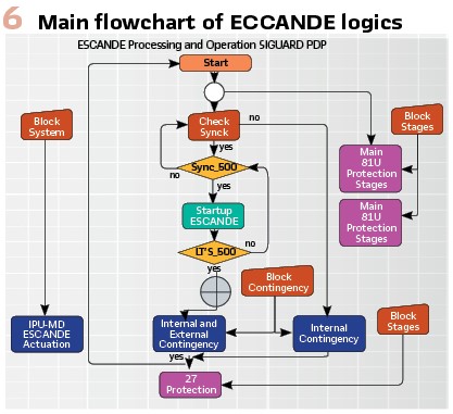
Figure 6 shows the main flowchart of the ECCANDE logic. Before the system will actuate different parameters must be checked and observed. Especially for external contingencies the arming conditions must be fulfilled. This is done by checking if the power system is interconnected and synchronized or not. Based on the angle difference of the line side voltages of the two 500 kV lines at the VHA substation this decision is made, if the voltage angle difference is lower than an absolute value of 5° and all the circuit breakers pertaining to both lines are closed, then the system is interconnected. In case of internal logics, a minimal active power flow on the 500-kV-transmission corridors must be detected otherwise the ECCANDE system will not actuate because no action from system stability perspective is required.
The under-frequency (81U) load shedding scheme is running always in parallel to the central logic and has main and backup stages. The under-voltage scheme (27) is only enabled if the ECCANDE system actuates and trips. The logic will release the under-voltage scheme depending on the detected contingency. All logics can be blocked manually by the HMI-interface.
Internal Contingencies and Logics: The most severe disturbances that can lead to system stability issues by the disconnection of Paraguayan transmission lines were considered as internal logic. These logics are event-oriented, and their terminology is related to the substations’ names presented in Figure 2:
- Logic 1 – EVENT: Opening of 500 kV MD-VHA IL
- Logic 2 – EVENT: Opening of 500 kV MD-VHA IL and 500 kV AYO-VHA TL
- Logic 3 – EVENT: Opening of 500 kV AYO-VHA TL or of the 500 kV AYO-YAC 1 and 2 TLs
- Logic 4 – EVENT: Opening of 220 kV MD-ACY 1 and 2 IL or of the 220 kV MD-IRY IL and 220 kV MD-PIH IL
TL = Transmission Line; IL = Interconnection Line
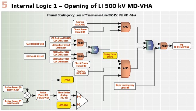
The general operation of internal logics is exemplified by Logic 1, illustrated in Figure 5. There are four central conditions to enable each logic: states of line’s circuit breakers ensuring the transmission line is connected, ECCANDE is initialized, HMI blocking and active power flow above the minimum reference, which is delayed 100 ms to avoid the effect of transients on the enabling condition. If all those enabling conditions are present in the logic, a line’s terminal opening of the 500 kV MD-VHA will generate the trip signal to all circuit breakers depicted in Figure 2. So, the ECCANDE system will separate back the two power subsystems.
The internal logics 2 to 4 operate in the same manner as internal logic 1. Differences are in the number of observed circuit breakers and in the threshold of the minimal active power flows.
External Contingencies and Logics: The external logics are related to severe disturbances associated to the shutdown of non-monitored equipment by the WAMPAC panels. Those unsafe conditions were related to monitored quantities identified by a large electromechanical simulation study, defining the following external logics which are parameter-based actions.
External Logics are parameter-based actions:
- External logic 1: OVERFLOW logic on 500 kV AYO-YAC 1 and 2 LIs
- External logic 2: REVERSE flow logic on 500 kV AYO-YAC 1 and 2 LIs
- External logic 3: ANGLE logic – Voltage Angle Difference between 500 kV MD & AYO busbars
Undervoltage-Control- and Underfrequency-Load-Shedding-Scheme: The load shedding schemes, which will be activated, if the ECCANDE system trips, are installed at the 220 kV transmission system level. All substations with feeders which will be shed are marked in Figure 2. The load shedding schemes are realized via a stepwise under-frequency scheme and a stepwise under-voltage scheme (in case of availability, capacitor banks will be switched on at certain locations). For both schemes different feeders in different substations are coordinated (tripped) via protocol IEC 61850-GOOSE message communication.
Both schemes actuate post system-splitting and are response-based actions. The respective substations and stages are described below:
- Underfrequency load shedding scheme: stages GUA (1), LIM (2), PBO (3), PCA (4), LUQ (5), COV (6), ACY (7), K30 (8), NORTH (9) which are always activated
- Under-voltage load shedding scheme: set I (stages 1, 2, A and B) and set II (stages 3, 4 and 5); which will be enabled by the operation of the ECCANDE system
The under-frequency main scheme has 9 stages with a grading of the frequency threshold, the delay time is set equal to 300 ms for all the stages. The backup scheme has 8 stages with the same frequency thresholds except for the first stage of the main scheme. The time delays are delayed in relation to the stages of the main scheme.
The under-voltage control scheme has 5 stages (1..5) for load shedding with 9 substations involved (corresponding to stages in the under-frequency scheme). Additional 2 stages (A, B) are related to capacitor banks which will be switched on if available, both will actuate under 0.9 p.u. with a time delay of 300ms. The set I actuates under 0.9 p.u. therefore the voltages at PCA, PBO and SLO are observed. If one out of these falls below the threshold, the delay timer starts for all stages in set I. For set II the voltages of COV and CYO are compared to 0.95 p.u., the delay timer also starts for all if any busbar voltage falls below the threshold. All three stages of set II are delayed in relation to set I and have a time grading of 300 ms. The control for starting the delay timers in different substations is realized with IEC 61850 GOOSE commands.
Testing and Commissioning
Before field commissioning, FAT was carried out in Colombia and additionally the system was tested in a RTDS laboratory in Germany. A reduced equivalent dynamic model with generator controllers (including PSSs), SVCs, HVDC load, and dynamic loads, was implemented, and tested together with a subset of PMUs. The protection functionality of the ECCANDE system was proved by simulating the most critical contingencies.
In the factory, the 24 PMUs were tested based on the proposed communication architecture, by testing the C37.118 protocol to the redundant PDC servers, by testing the IEC 60870-5-104 protocol between the PDC servers and the two redundant RTU pairs, and by testing the IEC 61850 (GOOSE) protocol communication from RTUs to 24 PMUs. All communication and functional tests were performed using the multiplexers and the MPLS protocol, which made it possible to carry out a process of debugging which helped to fulfill the performance requirements (contingency action time less than 150 ms) and to reduce the commissioning time on site (less than two months).
Fifty-four (54) days for the commissioning were necessary to guarantee the correct operation of ECCANDE scheme, live tests with the power system were carried out with good results. ECCANDE is currently online, safeguarding the whole system.
In the commissioning process it was necessary to test 16 substations in a short period of time, which led to testing 2 substations at the same time on some days. For example, testing at the same time one substation in Ayolas in southern Paraguay (about 250 km from Asuncion) with another substation in Ciudad del Este in eastern Paraguay (about 300 km from Asuncion), and correctly receiving all the information in Asuncion in the control center of ECCANDE (Villa Hayes substation).
One of the biggest challenges in the commissioning of the WAMPAC system, was to configure, to test, to debug and to send the WAMPAC system information to three different control centers: ANDE (Paraguay), ITAIPU (Paraguay-Brazil) and EBY (Paraguay-Argentina). The RTUs had to receive all the information from the PDC servers and to manage the sending of this information to the different control centers. It was necessary to use different IEC 60870-5-104 addressing and even deal with signal type changes because each control center had different IEC 60870-5-104 profiles.
The simultaneous use of up to 4 secondary injection equipment was necessary to test the different logics (internal and external) with GPS time synchronization to ensure the accuracy of the measurements and reaction times. In total, around 150 cases were executed ensuring the full functionality of all schemes, external, internal, over voltage and under voltage logics.
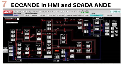
Figure 7 shows the HMI for the ECCANDE system which is implemented in the control center of Asuncion. All relevant PMU and RTU measurements are depicted as well as the status of the more relevant circuit breakers.
After rigorous tests in the factory in Colombia, in the RTDS laboratory in Germany and finally in Paraguay, the ECCANDE was connected to the national transmission system. To perform this task, prior preparation of the transmission, generation and dispatch agents was required, since it would be the first time that both electrical systems would be interconnected (Brazil, Argentina and Paraguay). Once the necessary conditions were achieved, a power switch opening maneuver was executed. This simulated a failure case, and the expected reaction of the scheme was to achieve the separation of the systems with the effective opening of the circuit breakers in the corresponding substations, reaching a total success.
Biographies:

Jonas Pesente received B.Sc, M.Sc., and D.Eng. in power systems in 2006, 2010, and 2018, respectively. He is currently a Senior Engineer at Itaipu Power Plant, where he works with disturbance analysis, electrical studies, power system protection, adjustment, and control tuning. He is also an active member of CIGRE and IEEE.

Robson Almir de Oliveira received B.Sc. and M. Sc degrees in Electrical Engineering from the Federal University of Itajubá, Brazil, in 1997 and 2001, respectively. He is currently an Assistant Professor at the Western Paraná State University, Foz do Iguaçu, Brazil and Senior Engineer at Itaipu Binacional.

Andre Pagani Tochetto received B.Sc and M.Sc. in power systems in 2006 and 2014, respectively. He is currently a Senior Engineer at Itaipu Power Plant, where he works with disturbance analysis and protection and control systems.

Alfredo Mezger received B.Sc and M.Sc. in power systems in 1997 and 2003, respectively. He is currently a Senior Engineer at Itaipu Power Plant, where he works with disturbance analysis, power system protection, adjustment and control tuning.

Elisandro E. Rodriguez B. received a B.Sc in 1997 and Power Systems Specialist degrees. He is currently a Senior Engineer at Administración Nacional de Electricidad of Paraguay, where he works in the Department of Electrical Studies. He is currently a professor of Electrical Protections at the National University of Asuncion.

Gustavo Aguayo is an electrical engineer that works for ANDE, with over 25 years of experience in the fields of maintenance and design of Protection. He holds BSc. (UFPR-BR) and MSc. (WSU-USA) degrees in Electrical Engineering.

Christian Romeis received Dipl.-Ing. and Dr.-Ing. in electrical engineering from the Friedrich-Alexander-University Erlangen-Nuremberg (Germany). He works as a Power System Consultant at Siemens PTI, performing studies related to protection system, wide area and Hardware-in-the-Loop testing.