by Walter Schossig, Germany, and Thomas Schossig, OMICRON electronics GmbH, Austria
Since this is already the 3rd part of the series covering the 1930s it is obvious that a lot of things happened in this century. A wide range of literature was collected for the German speaking countries but let’s have a look at the United States first.
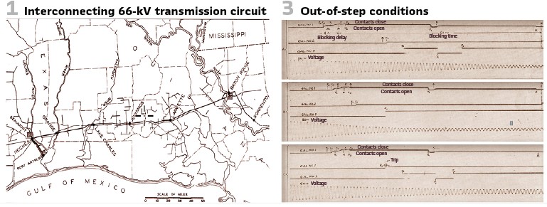
It was in 1939 when Vaughan and Sawyer (both with Westinghouse) published at IEEE a paper on testing the high-speed impedance relays HZ. The relays have been installed in 1931 and the test was performed interconnecting the 66-kV transmission circuit between Neches and Baton Rouge steam generating stations (Figure 1). The focus was on out-of-step blocking as well as selective tripping with impedance relays.
When two interconnected power systems pull out of step the relative values of voltages and currents are such as to indicate a three-phase fault somewhere in the interconnection, which if in the zone of high-speed impedance or reactance relays will cause them to trip their associated oil circuit breakers. Although this phenomenon was known already and various blocking schemes suggested, it has been generally accepted that when high-speed relays are involved, current or pilot wires gave simultaneous control of the relays at both ends of a protected section and have been required to discriminate between a fault and an out-of-step condition.
Transmission-line faults, other than those which can be prevented by reasonable measures, will occur occasionally, and must be tolerated. However, in addition to faults, instability occasionally develops due to disturbance elsewhere on the system, and the plants pull out of step, causing the relay to open one or more sectionalizing breakers.
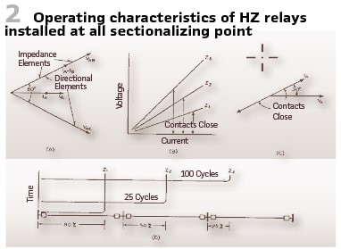
The type of HZ high-speed impedance relays was installed at all sectionalizing points. Each relay consisted of the high-speed impedance elements, a timer, and a directional element. Figure 2 shows the characteristics. The vector relationship of voltages and currents applied to relay elements at 100 per cent power factor (A), the relative characteristic of impedance elements (B), the angle zone between line current and line-to-neutral voltage that directional contacts close (C) and the time-distance setting of relays can be seen.
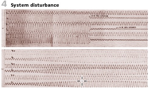
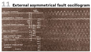
The typical oscillograms of voltage and current during system disturbance can be seen in Figure 4. Figure 3 shows the oscillograms with sequential operation of relays during the out-of-step conditions.
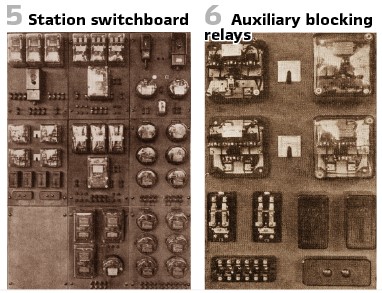
Figure 5 shows the station switchboard with two sets of HZ impedance relays on the middle panel and blocking relays on auxiliary panel to the left. Figure 6 shows two sets of auxiliary blocking relays with covers removed from one set.
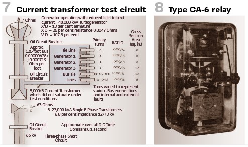
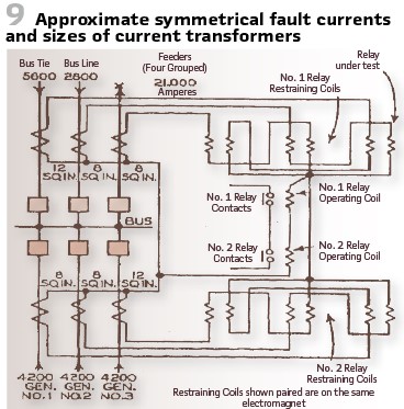
Another interesting test was described by Smith; Sonnemann and Dodds at AIEE. In a cooperation with Electric and Manufacturing Company, Newark, and Duquesne Light Company, Pittsburg they shared their experiences on applying ratio differential relays for bus protection. The paper describes the impact of CT saturation and introduces a new bus differential relay- the CA-6 (Figure 8). Tests on the relay, which has been described, were made under conditions similar to those that would exist if it were installed to protect a 66-kV bus at a large generating station. Conditions simulated were as shown in Figure 9 and consisted of five sources representing supply from four transformer banks and a bus-tie breaker, and four transmission lines. The current transformer for only one of these 4 lines were used, since it was assumed that a fault would exist on only one of the lines at a time. The figure shows the bus setup, fault currents and relay connections. Constants of the test circuit as well as the current transformers used with their approximate cross section of iron, and their turn ratios, are shown in Figure 7. Figure 11 shows an example recording.
As announced, we are now going back to Germany. The organization VDE had an own group on “Relays and protection circuits” (A III). In 1936 they published an interesting report. The title “Functional testing methods for selective protection” (“Zweckmäßige Prüfverfahren für den Selektivschutz”). It is interesting to see, that sources of errors have been identified already, since they had an impact on protection’s reliability and failures. Practical methods for testing have been covered.
They proposed to extend the common testing interval at this time (which was 4(!) weeks). Depending on manpower available and the type of relays tests have been recommended less or more often. A typical example was a replicate test after two or three months. This period was extended locally often. If the replicate test was performed often enough, they learned what could be a good interval to guarantee safety of relays the period should not extend five or six months. “The industry needs reliable protection devices. Even with different vendors the setup should be comparable and there is a wish for interchangeability.”
The conclusion was that to reach this, general rules and specifications for relays should be developed.
The details have been described in a paper, written by Rimmark, who was with SIEMENS, in 1936.
The selective protection made huge progress over the last years, using the experiences collected. We reached a high degree in perfection already. Nevertheless, periodic testing and maintenance stay important. This is also important since the reliability of the systems does not only depend on the relay itself but also the wiring and contacts. Also, the auxiliary power supply as well as the mechanical elements of the disconnectors and breakers must be in good condition. It is known from the railway system, that the signals have to be checked regularly to achieve highest reliability – this is valid for protection as well. Considering the statistics, it is obvious, that the amount of not properly maintained relays is as big as not properly working switchgear and connections. The reliability could not be improved by just making the relays “stronger”. More force means bigger mechanical parts, more weight and more mass acceleration. The main advantage of supervision and testing of the entire system proofs the entire chain as during the commissioning. Elements and contacts might stick together, even if they are cleaned regularly. Regular testing shows the wearing of the elements. Increased operation time is a good indicator. Documenting the times continuously delivers valuable information and indicates if cleaning and maintenance of the relay is necessary.
To test secondary equipment, several setups have been developed to allow easy testing. Setups with hand gear, automatic short circuit devices and test plugs all have one goal- allowing an easy connection of the test set. Eliminating the connection to the VTs and CTs shall be avoided in any case. The best testing is the test with relay in operation with load current. The relay shall stay in operation during the test. It shall be checked that startup and trip appears in right order. Injecting current shall test the connections. The test plugs should be close to the measurement transformers.
The practical realization shall be explained with several examples.
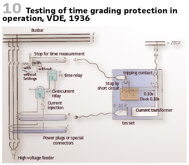
Not so complicated is the testing of simple overcurrent, time, and directional elements. Figure 10 shows the setup.
The auxiliary contacts allowed to measure operating time of the relays as well as the operating time of the circuit breaker.
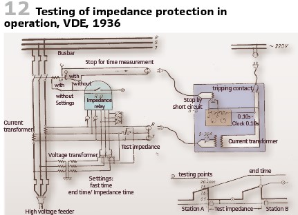
How to test impedance protection can be seen in Figure 12. The changeover switch allowed the disconnection of the AC voltage, so the smallest tripping time could be measured. If the full voltage was connected the end time could be measured. With the resistance all values could be set, and the entire relay characteristic could be measured.
Undercurrent startup elements could be tested by injecting sufficiently high current (Figure 13). The testing current operates an auxiliary relay, which is connected to a voltage divider.
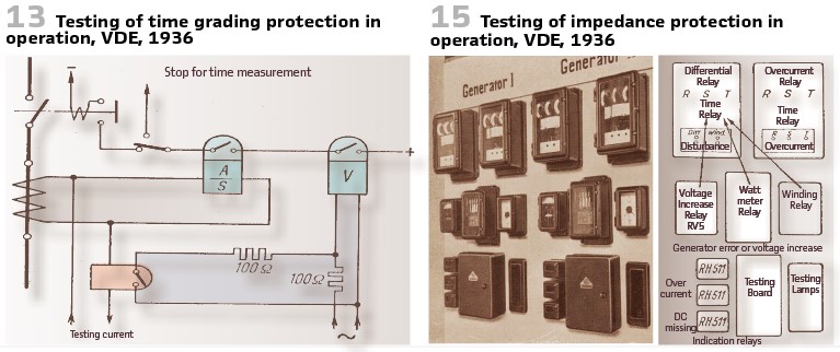
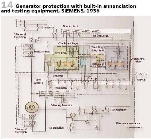
Another example for the planned combination of different elements for generator protection testing is the “test button cubicle” produced by SIEMENS in 1936. Figure 14 shows the scheme of generator protection at busbar operation with integrated annunciation and testing. According to the relay setup single and multiple buttons are prepared to connect the resistances and limit the current injected. Pressing the buttons starts the different elements. The tripping contact will be connected to the testing device instead of the circuit breaker. Lamps indicate the proper operation. A roller gate takes over the switch over. Opening the device switches over to the testing lamps. The cover closes autonomously, strong springs switch back to protection mode and the protection works properly automatically. Figure 15 shows the board.
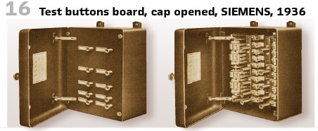
Additional contacts could extend the system even to test fire alarms or to shut down the generator As a current source the current generator itself can be used or (in case of motors) the grid. To do so and as shown in Figure 14, the test circuits will be connected to the machine and the three-phase voltage transformers. A small additional transformer might be utilized to avoid fluctuations of voltage during the test. Such a test setup (Figure 16) was very important. It was useful, to let the relays operate from time to time. In normal case it might take years, until the relay must operate, and it is essential that the relay works as perfect as on the first day.
During such a test any issues could be found and fixed immediately. Also, for the engineers working with the relay and its test increased additionally the knowledge.
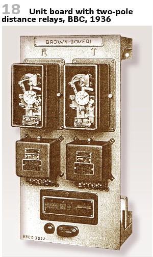
The main task of a distance relay is to selectively protect the high voltage transmission lines against short circuits and double earth faults. This required auxiliary relays at this time, so the efforts for wiring and troubleshooting have been high. That is why “unit relay boards” have been developed. Those boards could be prepared and tested in the forefront already containing all relays and connections. On site it was sufficient to connect CTs and VTs as well as the tripping connections. Figure 18 shows such a board. It is made of steel and contains distance relays. On top is the name plate with feeder’s name. Next are the distance relays for phase 1 and phase 3. The switch-over relays are on the right, the sum-relay on the left hand-side. A cap covers test plugs. On the very bottom is the supervision lamp for the DC voltage. To set up distance characteristic additional tuning transformers are in use, they are on the back
It was important to have a proper and easy to use relay setup and testing. The test equipment shall check properly the functionality and availability of the entire protection system.
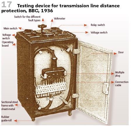
Known test sets at this time could not fully satisfy the users – the interruption of the operation as well as the huge efforts for wiring causing a lot of manpower have been disappointing. That is why BBC developed an own distance protection test set (Figure 17). Now it was possible to test the distance protection without interrupting the service. The injected values shall be similar as in real faults. The test equipment contains impedances and auxiliary transformers representing the line connected to the relay. Again, the test equipment is powered by the station battery or the voltage transformers. A multi-plug as shown in the picture allows easy connection. The test set comes on wheels and is equipped with several switches as well as voltage measurement. Utilizing a switch between the different phases could be chosen for measurement and testing. 8 different fault types could be selected. The following scenarios have been possible:
Position 1: Grid with voltage but no current:
- The distance protection devices do not startup, the voltmeter shows the voltage.
- This allows testing of the power supply as well as test set itself
Position 2: 3-pole short circuit:
- The distance relays shall trip within the same time, and this shall be indicated
- All indicating disks are operating simultaneously, indicating proper operation of the distance protection. The auxiliary relays do not operate, the signal lamp indicates when the relay trips
Position 3-5: 2-pole short circuits, cyclic order:
- The distance relays affected shall operate simultaneously, then the auxiliary relays worked properly as well:
- Lamps as before
Position 6-8: Doubled earth fault in cyclic order:
- As explained before
The testing engineer was responsible to fill out a sheet documenting all the tests made.
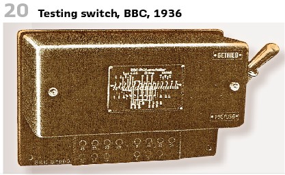
This was huge effort. But for very important substations, several such test sets have been used. To allow easy connection, even for engineers without experience, an additional test switch (Figure 20) was developed. It allowed switch between Operation (“Betrieb”) and Test (“Prüfung”). Inside this switch there was a controller cylinder managing the connections, also taking over the short circuit of the current transformer. An additional lamp indicated operation.
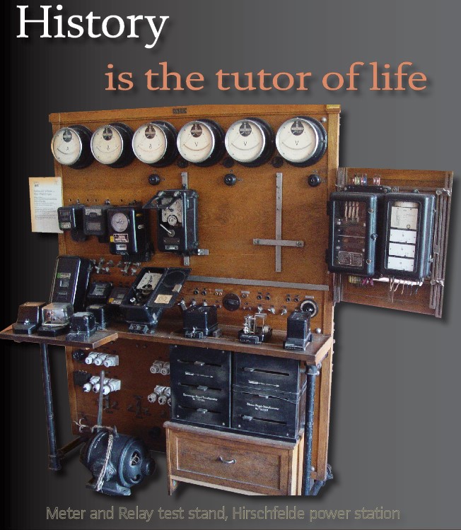
The Figure on the top shows a meter and relay test stand at power station Hirschfelde in Germany in the 1930s. It is easy to recognize the reostat for the three-phase voltage and current regulation transformers. The motor operates as phase rotator. The devices under test are the directional overcurrent protection RW5 (SIEMENS) and the timed overcurrent protection RSZ3f (AEG).
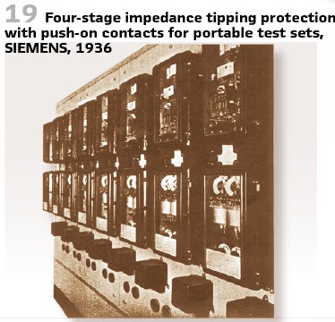
There was a demand, not to open any connectors or change wirings when doing a test. Also, switchovers should be avoided. They have been afraid, that engineers forget to remove them. Therefore, testing push-on contacts have been used (Figure 19). With all this even in complex arrangements testing became much easier. With superimposing the testing current to the operational one, all startup elements have been triggered and the protection had to trip. Those tests affected the entire chain, including the wiring. It was possible to supervise every relay in operation.
In the 1930s, the amount and the importance of protection devices increased dramatically. So, the German VDE (Verband Deutscher Elektrotechniker) decided in 1938, to publish binding rules for relays. Until this, every vendor and every utility could take fitting values from the “regulations for switchgears” (RES) and the “regulations for installation material” (KPI). To avoid problems some utilities had already published own standards. To achieve consistency rules the VDE was approached. Several meetings took place and preliminary. Unfortunately, World War II caused a stop to the work since several members of the committee were not available.
Thus, it took some time for binding rules in Germany. It was in 1962 when the “Rules for electrical relays in power plants” for Germany have been published as VDE 0435/9.62 by VDE.
info@walter-schossig.de www.walter-schossig.de
thomas.schossig@omicronenergy.com
Biographies:

Walter Schossig (VDE) was born in Arnsdorf (now Czech Republic) in 1941. He studied electrical engineering in Zittau (Germany), and joined a utility in the former Eastern Germany. After the German reunion the utility was renamed as TEAG, Thueringer Energie AG in Erfurt. There he received his master’s degree and worked as a protection engineer until his retirement. He was a member of many study groups and associations. He is an active member of the working group “Medium Voltage Relaying” at the German VDE. He is the author of several papers, guidelines and the book “Netzschutztechnik [Power System Protection].” He works on a chronicle about the history of electricity supply, with emphasis on protection and control.

Thomas Schossig (IEEE) received his master’s degree in Electrical Engineering at the Technical University of Ilmenau (Germany) in 1998. He worked as a project engineer for control systems and as a team leader for protective relaying at VA TECH SAT in Germany from 1998 until 2005.
In 2006 he joined OMICRON as a product manager for substation communication products. He is author of several papers and a member of standardization WGs.