by Walter Schossig, Germany, and Thomas Schossig, OMICRON electronics GmbH, Austria
When electronics entered substations, this happened as static relays. With the introduction of this technology there was a need to clarify testing conditions, operations, and power supply. The utilities in Western Germany founded a working group at VDEW. It was called “Future protection” with the task to discuss recommendations within the industry. One of the main intentions was to discuss how to group the different functions within the relays to achieve interchangeability.
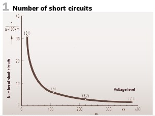
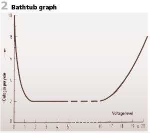
VDEW also published the numbers of short circuits per year, related to the length of lines. The values in () represent the medium between 1972 and 1976. The amounts of short circuits depending on the voltage level is shown in Figure1. Electronic elements tend to be getting old. This is also a function of operating time; the graph is called bathtub (see Figure 2).
Static relays have been tested at the vendors already according to the German standard VDE 0435 “Rules for electrical relays and power plants”. Additional tests have been added, like impulse test and high-frequency disturbance test, both taken from appendix E of IEC publication 255-4. At this time the working group “Static relays” of SC 41 B “Measuring relays” of IEC was working on the topic testing procedures. Several countries started to specify tests before IEC. Those standards, as well as s the implementation of the vendors contained “killer circuits” to guarantee EMC. The noise spectrum applied was as of switching in DC circuits. This was not so easy to apply to practical and standardized tests. Until 1974 already 50 papers were published on electromagnetic influence (EMI) and how to handle it.
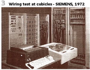
The more electronic components were used, the more important was the quality of the components. Components as metal film resistors, film capacitors, transistors, and diodes should be specified according to the US MIL (military) definitions. All elements have been type tested before they could be built into the protection cubicles. For instance, transistors have been selected considering their characteristics and current gain. The building blocks have been tested in addition. Climate tests (VDE 0160 and VDE 0435,) impulse tests (VDE 0228) and interfering voltage tests were according to British BEAMA standard (5 kV, 1.2/ 50 µs). IEC’s TC 41 published additional tests with HF. This was done as type tests. Additionally, a functional check according to VDE 0435 (2 kV, 1 minute, connected to CT and VT and circuit breaker) was mandatory. Figure 3 shows the test at SIEMENS, checking the wiring, utilizing automated testing with device VD20.
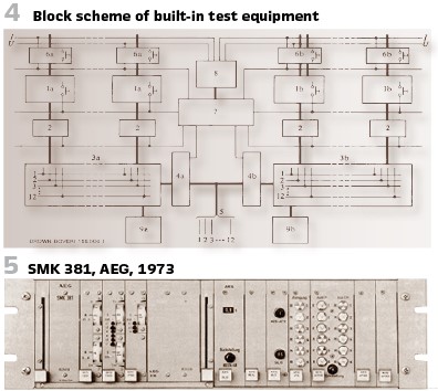
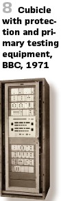
BBC published papers on static protection in 1971. They built bigger units consisting of two groups of relays. This allowed the realization of main1/ main2 / backup protection. Also, the testing could be separated. Figure 8 shows an example of generator protection. The test equipment could be built in, Figure 4 shows the block diagram.
1 = Protection relays
2 = Tripping contactors
3 = Tripping matrix for tripping program
4 = Tripping circuit interruption
5 = Tripping circuit
6 = Inputs for test values
7 = Control and interlock device
8 = Source for generating test Values
9 = Monitoring device for testing tripping circuits (effective up to tripping coils of respective main breakers)
a, b = Relays and devices of test groups 1 and 2 respectively
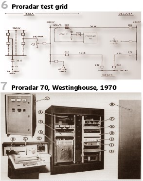
A very important paper on static protection was the paper “HIGH-SPEED DISTANCE RELAYING USING A DIGITAL COMPUTER” by Gilcrest, Rockefeller, and Udren in 1971. Figure 6 shows the test grid for the Proradar 70 (Westinghouse, Figure 7) at PG&E.
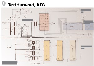
Another vendor in Germany was AEG. The SMK 381 was called “rack-mounted protection relay.”
To test this electronical relay AEG delivered a “Testing turn out” (see Figure 9).
This testing turn-out contains three-phase autotransformer to generate the testing currents. It was connected to 220 VAC, 50 Hz. The secondary winding came with several taps, so the current range from 0.1 …. 30 A could be chosen (6 steps). The phase to be tested (R, S, T) could be selected as well. An additional winding allowed to power auxiliary relays and tripping coils. Once the power supply is connected, the button S1 starts the test.
The current range was selected (Bu) and adjusted precisely with the knob. The device under test has to be plugged into the empty slot. The current is connected and visualized with a pointer. 8 LEDs could indicate any binary information. The coupling element could be configured to adapt to different types of relays. The time was visualized on the display SL1 (10 ms…999.99s) The testing device was single phase, one phase was tested after the other.
BBC proposed in 1977 “fully automated testing of static generator protection”. The routine and periodic testing should be replaced by built-in variant. The costs were 15% of the entire protection system. The main goal was to test the start-up values automatically (Figure 10). After this the functional test should be obsolete. Please note that the functional tests at this time were mandatory every single or second month. The startup values were tested after some years again.
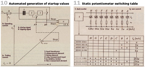
To generate the variable values “static potentiometer” were used. This shall avoid mechanically operated parts as in conventional potentiometers (Figure 11).
The static potentiometer consisted of 8 resistances (A-H), connected to AC via triacs. The 8-bit binary counter 1 with his 8 outputs is connected to triacs’ control ports. When the counter is counting, the current is increasing in 256 steps from 0 to 255 a A (a is dimensioning factor in this case) The increasing current is the testing current. Once the relay trips, the signal A stops the dual counter 1, the detected relay startup value was stored.
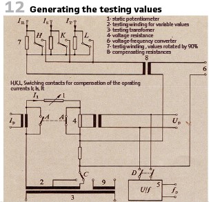
How the testing values were generated, can be seen in Figure 12.
The automated test logic could test 52 phases sequentially. Three phase tests demanded the phases and positions, of course. How the different phases should be tested had to be configured on a 52 x 12 diode matrix.
All testing results (measurements A, V or Hz) and the corresponding times could be evaluated. Measurements and times will be available on the display for 10 seconds. All the measurement values (52 values and times) are stored in the PROM as minimum and maximum values. A comparator calculates the desired value deviation. If the value is out of range, a warning will be shown. A star is appearing as a mark in the protocol. The failed test can be repeated by pressing the button.
All test results can be printed out.
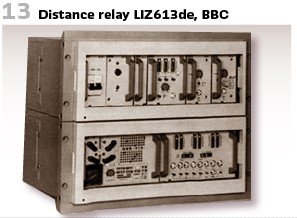
The electronic distance protection LIZ613de (BBC as well) could be tested with test button available. To do so the switch has to be set to position “test.” This allowed to test relay R, S, T, and E as well as the measurement system and timing element. Additionally, a test plug is available after removing the front plate. Testing device QZW can be connected. This allowed testing of the entire system. (Figure 13).
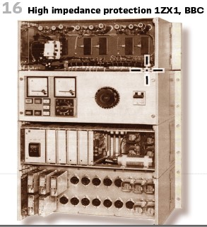
Another example is BBC’s high impedance protection 1ZX1.
1. level: voltage supply
2. level: test and signal equipment
3. level: Measurement and control electronics
4. level: tripping elements
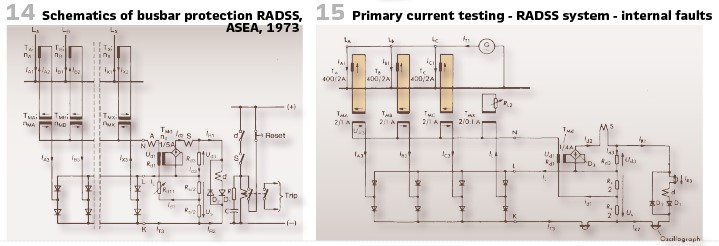
ASEA was at this time a company in Swede and their static protection RALDA was tested in the May of 1973 on-site. The distance protection RADSS achieved tripping times of 7 ms (see Figure 14).
The test circuit of Figure 15 was used to check the operating characteristic of the protective system during internal faults by primary testing.
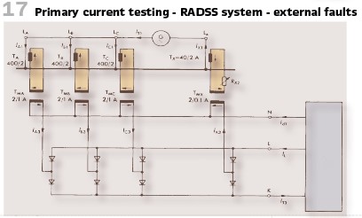
Also, for external faults this system was applied (Figure 17).
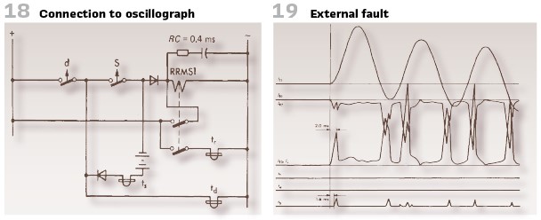
For recordings everything was connected to an oscillograph elements to observe all relay contact operations during primary current tests.
The oscillogram of a test with external fault of 24 kA (62 kA) is shown in Figure 19. The differential output relay correctly did not operate.
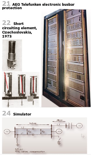
Also, AEG -Telefunken in Germany came with an electronic busbar protection (Figure 21) at this time. As well as the competition, it came with built in testing.
Functional tests of the measuring circuit, the logics implemented, and the phase comparison scheme was implemented. As in the other implementations it could be operated by pressing a knob. A clock enabled time shifted testing as well. The test could only start if there was no sum current startup at this time. This means that during busbar fault or in case of backup protection operation the protection could work properly.
At the very beginning, the DC supply of the trip relay is interrupted, and the operation of the control checked. After these all-phase combinations were applied, internal and external fault is tested. In case of problems the protection will be blocked. The duration of a complete test was 10 seconds only. In case of a busbar fault the test will be interrupted, after 15 ms everything will work again.
At the end an interesting episode out of Walter’s professional life. In the 1970s short circuit elements (Figure 22) instead of circuit breakers have been tested at utilities in Eastern Germany. The devices were produced in Czechoslovakia and were used on the high voltage side of 100-kV circuit breakers. A breaker test was mandatory during commissioning, so now this device (it came with patrons which had to exploded) needed to be tested. Not everybody liked the idea at this time. Explaining the measures (reduction of operating time of the remote distance protection, redundant protection in coupling) it could be done. And what happened? One of the sticks was flying through the air, only one reached the line. For the constructors this was the sign, to work with mirrors for calibration in the future.
With a small journey around the globe in the 1970s we will finalize this article.
Several huge developments came from the 1970s. In Australia, Mann and Morrison of University of N.S.W. presented at the IEEE summer conference in Los Angeles in 1970 a computing program for digital line protection. Fault current limiters were presented at the 1973’s IEEE Summer Power Meeting and the first Computer-based SCADA system was introduced at ESCOM South Africa in 1977.
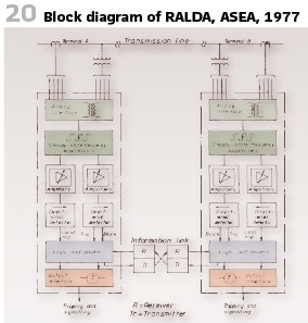
It was in 1978, when Chamia and Libeman of ASEA in Sweden presented an ultra-high-speed relay for EHV/ UHV transmission lines. Basically, the RALDA-system operates in a directional mode, i.e., requires use of a communication link between relay terminals. Dependability and speed of operation have been further enhanced by the provision of a parallel mode of operation requiring only one additional directional detector unit. This unit has an underreaching setting similar to a zone one type of relaying enabling local circuit breaker tripping without the need of a communication link. This mode of operation is intrinsically selective and since it does not require time coordination it is particularly valuable for ultra-high-speed clearance of close-in faults. Typical operating times of 2-3 ms are possible in this mode. The directional comparison blocking mode has essentially the same response time, but the communication link introduces an additional delay. A block diagram of the relay system is shown in Figure 20.
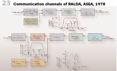
In such a system the communication was essential (Figure 23). The later stage of the prototype testing necessitated a series of laboratory tests. Part of BPA’s 500 kV system was simulated on an analog Transient System Simulator (TSS) with network configuration according to Figure 24 where the lines were modeled with the proper frequency dependence considering the shunt capacitance and mutual coupling effects as well as shunt reactor and series capacitor compensation. For the purpose of investigation, a fictitious large 525 kV shunt capacitor bank was also included. A large number of tests were recorded using a 14-channel analog tape recorder. The recordings were then fed back into the relay.
info@walter-schossig.de www.walter-schossig.de
thomas.schossig@omicronenergy.com
Biographies:

Walter Schossig (VDE) was born in Arnsdorf (now Czech Republic) in 1941. He studied electrical engineering in Zittau (Germany) and joined a utility in the former Eastern Germany. After the German reunion the utility was renamed as TEAG, Thueringer Energie AG in Erfurt. There he received his master’s degree and worked as a protection engineer until his retirement. He was a member of many study groups and associations. He is an active member of the working group “Medium Voltage Relaying” at the German VDE. He is the author of several papers, guidelines and the book “Netzschutztechnik
[Power System Protection]”. He works on a chronicle about the history of electricity supply, with emphasis on protection and control.
Thomas Schossig (IEEE) received his master’s degree in Electrical Engineering at the Technical University of Ilmenau (Germany) in 1998. He worked as a project engineer for control systems and as a team leader for protective relaying at VA TECH SAT in Germany from 1998 until 2005.
In 2006 he joined OMICRON as a product manager for substation communication products. He is author of several papers and a member of standardization WGs.