by Mital Kanabar and Jeff M, GE Renewable Energy – Grid Solutions, Canada
In 1982, GE’s first commercially available microprocessor based Protect4A relay revolutionized the industry on convergence of functionality into small and compact hardware. Figure 1 illustrates the evolution of protection devices and related technologies. The historical evolution of protective relaying technology has significant influence from Electronics and Communication developments in the past.
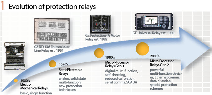
The historical evolution of protective relaying technology has significant influence from Electronics and Communication developments in the past. And, the next generation of digital protective relaying is also receiving directions from evolving technology trends of Industrial Internet of Things (IIoT), virtualization, digital interfaces of combined optical CT/VT and circuit breakers, as well as digitized primary equipment. Figure 2 illustrates the differences in various technology evolution cycles related to the substation protection, automation and control system.
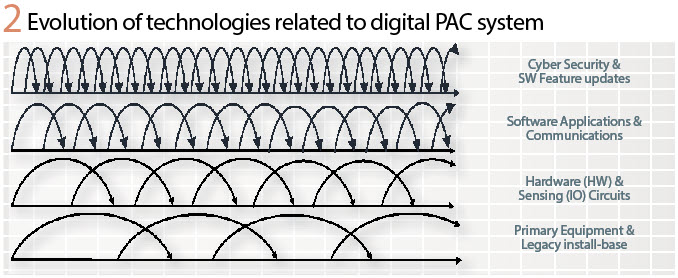
The technologies of primary equipment and legacy system install-base stay in service around several decades before they are migrated to next generation technology. Ruggedized and digitized remote input/output hardware electronics including sensor circuits can be simplified and stretched to few decades to align with maintenance cycles of primary equipment. The cycles of software applications and communications technologies are typically evolving at a faster rate; whereas, cyber security applications and specific software/firmware may need an update more frequently depending upon specific requests or yearly feature update cycles.
Architecting Digital Substation PAC System
Figure 3 shows the hierarchical architecture of a digital substation PAC system, and divided into 3 existing levels: process, bay and station. Considering the technology cycles discussed earlier, the process level needs to ‘simplify’ with digitization using open standard data sharing communication interfaces (i.e. IEC 61850-9-2LE and/or IEC61869-9/13). Bay level should be able to ‘converge’ PAC applications and allows virtual isolation of PAC IEDs and equipment maintenance. The modularized hardware of PAC IEDs can provide completely independent communication ports to facilitate cyber security perimeter segregation for process bus and station bus. The station bus can ‘virtualize’ station applications for grid of the future readiness. As the grid evolves (e.g. Renewables penetration), the scalable substation control & automation platform may also allow future applications and solutions without replacing hardware and/or platform software.
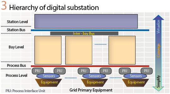
The Process Interface Units (PIUs) installed close to primary equipment merely digitize the signal interface and communicates to process bus over interoperable IEC 61850-9-2 or IEC 61869-9/13 standards. The software and settings at process level needs to be minimum or if possible, settingless with segregated layer-2 (Ethernet) level traffic. Easy to install and maintain hardware delivers higher reliability, and with interoperable protocols, this data would be available to any applications at bay or station level, and it will also allow virtual isolation using IEC 61850 Test/Sim mode explained later in this article.
The allocation of protection or related intelligent functions at the process level should be evaluated carefully by utility PAC leadership teams for air insulated substations (AIS) for T&D. The protection functions distributed across the switchyard would not only require extensive maintenance firmware/software upgrades, but also maintenance testing. The protection settings and related scheme logic need to be tested in the switchyard with the secondary injection test sets. Protection devices with OSI layer-3 (IP – Internet Protocol layer) interface availability may need considerations from a cyber security perspective as well. Therefore, instead of protection IED, the architecture should consider simplified PIU (only digitized CT/VT and circuit breaker) interfaces over standard communication protocol.
Evolution of digital interfaces readily available from the optical CT/VT, circuit breakers, and digitized primary equipment would eventually replace these simplified PIUs. Therefore, the future-proof architecture should not include traditional protection functions and their scheme allocated at the process level. The performance of protection messages from PIUs, e.g. sampled value (SV) and GOOSE should be as fast & secure as possible. The reliability and dependency requirements on communication network at process level can be addressed with redundant streams of SV/GOOSE with advanced monitoring at bay level PAC IEDs. Furthermore, the point-to-point architecture can also eliminate the need of Ethernet switches and IEEE 1588 PTP clocks for higher resiliency for PAC applications.
If simplified protection functions with separation from automation are required, the converged-bay level protection functions concentrated into few hardware IEDs at bay level still have more advantages over the protection distributed across the switchyard.
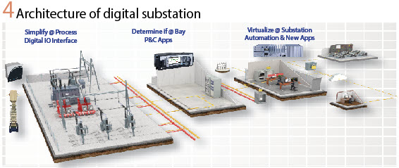
Figure 4 illustrates the future-proof digital substation architecture, which not only reduces CAPEX with fast and easy installation, but also optimizes OPEX with virtualized IED isolation for maintenance and testing.
Therefore, the drivers of the future substation are: simplify the process level; converge at bay level, and virtualize at station level.
Automated P&C Testing using Virtual Isolation
If protection functions are allocated at the process level, similar to traditional testing practices, they require hundreds of testing steps which require time to reconfigure the devices and testing connections as well as create room for errors or mistakes. A utility’s existing test plans can be modified to streamline the testing process per device or scheme. Once the data within the digital messages are configured and assigned to the test set software, the only requirement is to click a button and the test will be completed in a significantly reduced time and resource. Most testing can be done off site which can reduce commissioning and outage times. Traditionally, protective relays at bay level are physically isolated for maintenance or expanded bay commissioning using external test switches. This requirement will move to the switchyard if protection functions/relays are installed across the switchyard. With advent of IEC 61850 communication enabled protection schemes, only physical (copper wire) isolation of the relay is not sufficient if it is communicating GOOSE over Ethernet for integrated protection scheme.
With IEC 61850 and test set capabilities to allow uploading and linking of parameter settings as well as GOOSE and Sample Values into a test plan, the test process becomes mostly automated. Relay settings and configurations no longer need to be modified for every step in the test plan when all the logical nodes required for your test are published in a GOOSE message onto the network.
When implementing a digital substation using IEC 61850, it is necessary to design the system for testing. This means defining methods for virtual isolation to test specific devices and functions without risk of undesirable operations of in-service equipment. (see Table 1).
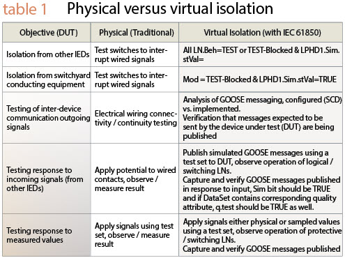
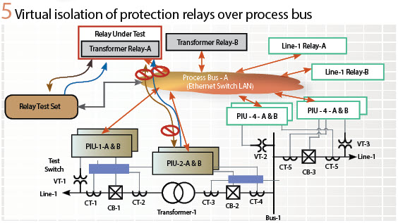
A way to think about the concept of virtual isolation is shown in Figure 5, where Transformer relay for system-A is virtually isolated by the relay test set using IEC 61850 Test/Sim modes. Once the transformer relay-A is in the test mode, it will ignore all the data/information received from other devices such as PIU-2-A&B in the figure; similarly, PIU-2-A&B will also ignore GOOSE from the transformer relay-A. Instead, Transformer relay-A will exchange SV and GOOSE from the relay test sets, in order to automatically run all the protection function test scripts. Upon completion of test, the transformer relay-A can be put into operation by disabling IEC 61850 Test/Simulation modes. Thus, physical test switch isolation, CT terminal shorting and related safety hazardous manual operations are eliminated. Since, the PIUs are simply analog to digital conversion circuits with data circuits, the testing of these PIUs can be validated with either cross-checking of SV streams from PIU-A & B or if required through simple metering of secondary injection tests.
Proactive Protection Applications
Reactive to Proactive Protection Applications: The majority of today’s protection functions in a digital protection relay are high-speed and secured; however, these protection functions are still reactive by design. Reactive functions respond to a disturbance or stimulus event occurring in electrical equipment; these functions are designed and applied to measure, calculate, and react to an undesirable situation to protect electrical equipment, limiting the damage incurred.
Although protection relays are utilizing the latest digital platforms, the core principles of protection functions are merely a digitized formulation of electromechanical operation. For example, disc-type electromechanical relay principle is digitized using time-current inverse curves characteristics to imitate the disc travel time as a function of magnitude of the current. In most cases, the damage to the protected equipment is already done. It is observed that the protection relay has operated as expected (within 1 cycle of operation time), however, it may still incur losses to the utility system or industrial facility.
The advancements in data analytics, interoperable data communication, high-speed networking, the availability of data for advanced analytics are opening a new era of proactive protections which do not just limit but can prevent catastrophic events. Digital protection relays are checking for the anomalies typically every 2ms. Instead of witnessing the evolution of equipment failure until the set threshold of traditional protection function is reached, the proactive protection can provide early warning upon detection of abnormal operating conditions.
With the deep equipment design expertise, the proactive protection functions are designed to continuously perform online equipment condition monitoring in combination with Protection & Control (P&C) measurements of the equipment to be protected (e.g. motor, switchgear, transformer, generator, etc.). Proactive functions take a holistic approach to the asset/equipment to be protected, and capture the entire evolution of a failure, including a) detecting an anomaly or degradation of a subcomponent of the asset/equipment, b) alarming the condition and c) recording and logging the signals and evolving changes. Proactive functions are essential to detect critical asset degradation or anomaly conditions before it evolves into catastrophic failures. A few examples of transformer, breaker/switchgear, and motor related proactive functions are explained in further sections.
Proactive Transformer Applications: Power transformers are one of the most critical assets of a power substation required to maintain the reliable and efficient power supply. Yet more than half the transformers in the developed world are 40 years old, or older. With 52% of transformer failures caused by insulation degradation and electrical abnormalities due to aging, extending the life of these devices has become a top priority for major power utilities.
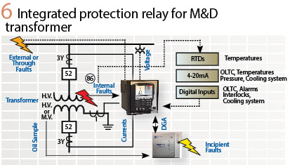
Traditionally, a transformer protection relay is connected to current and voltage transformers to obtain the currents and voltages needed to detect electrical faults and is interfaced with breakers for control actions. In addition, Dissolved Gas Analysis (DGA) devices connected to a transformer can draw oil samples on a regular basis and perform continuous chemical analysis. In the past, these two distinct systems (electrical protection and chemical monitoring) have not been interconnected. Since both systems provide much-needed asset and performance management data, bringing them together provides a more comprehensive view of the transformer’s overall health as shown in Figure 6. This integrated approach of combining two systems (one protection relay with electrical functions; a second DGA with chemical analysis) allows tracking of trending incipient fault events with the same time stamps, correlation between the electrical and chemical models, and integrated asset health analysis and reporting.
Several standard gas analyzer models exist that conform to IEC and IEEE standards, including Duval’s triangle, gas ratios, and key gas. An integrated protection relay approach eliminates the need for manually correlated data for post event analysis. Instead, the DGA device is connected to the protection relay. It imports chemical data on an ongoing basis, compiling reports, and presenting the analysis back in a practical, actionable fashion. This reduces reliance on offline experts and laboratories; the data is readily available in the system. This type of continuous monitoring can show a transformer fault’s characteristics moving from one point to another, as well as the ratio of gases during each stage of the fault. This powerful tool aids in understanding the speed at which degradation, or a fault condition, is evolving.
Data correlation models: The models in a protection relay provide the ability to correlate electrical, chemical and thermal data, allowing for the creation of individual trending models. Such models help identify correlations between different but inter-related sets of data, such as a record of transformer loads compared to gas concentration data.
A correlation model will help spot, for example, that a gas concentration is occurring every time a transformer is loaded in a particular way. This model can then be used to track transformer load, temperature, and gas concentration changes in order to identify any relationship between one measure and another. This in turn allows operators to proactively safeguard transformer assets, extending the time before a shut-down for maintenance or decommissioning is required.
Integrated electrical and chemical analysis is further used to achieve the following:
- Energization records: record transformer inrush parameters, such as Peak inrush current, max voltage dip, volts/hertz, and 2nd and 5th harmonics
- Transformer fault reports: capture chemical and thermal data for internal faults or through-faults.
- Transformer health reports: compile operational and fault data, allowing benchmarking and identification of deviations from normal operating conditions. The asset management team can utilize this readily available report for post-event analysis and archival purposes.
An asset health report gives a snapshot of the transformer condition, and helps utilities analyze the following:
- Risk assessment of the transformer population in service, especially critical transformers and important connections.
- Condition assessment of individual transformers, identifying those which may require follow-up such as visual inspection, diagnostic measurements and maintenance.
- Life cycle decisions for the transformer: Determine if retirement, refurbishment, replacement or relocation necessary
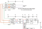
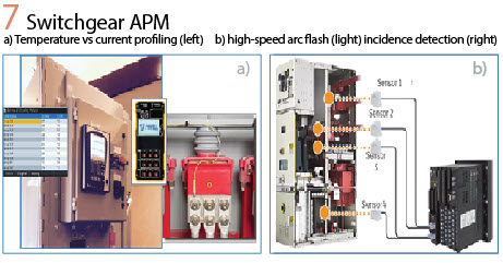
Proactive Breaker/Switchgear Applications: The primary function of a switchgear breaker is to isolate a fault element by interrupting the high short-circuit current, which results in stresses in the switchgear. Advanced IEDs can track statistical performance of the breaker based on arcing currents, duration of operations, number of trip/close operations, etc., as well as monitoring trip and close coils and breaker pole discrepancies. In addition, an advanced IED has the capability to act as a generic data protocol master to collect external sensor data and synchronize all information, creating data correlation models and providing asset monitoring and diagnosis. The example in Figure 7 a) illustrates a switchgear temperature monitoring sensor interfaced with an advanced IED over Modbus TCP/IP, profiling temperature vs current correlation. This allows for optimum utilization of switchgear assets. Furthermore, switchgear arc flash protection can be achieved by interfacing light sensors installed in the switchgear directly with the advanced IED for enhanced safety without installing additional devices.
Proactive Rotating Machines Applications: Rotating machines are one of the most important components of any industrial plant, ensuring productivity along with reliable and safe process operation.
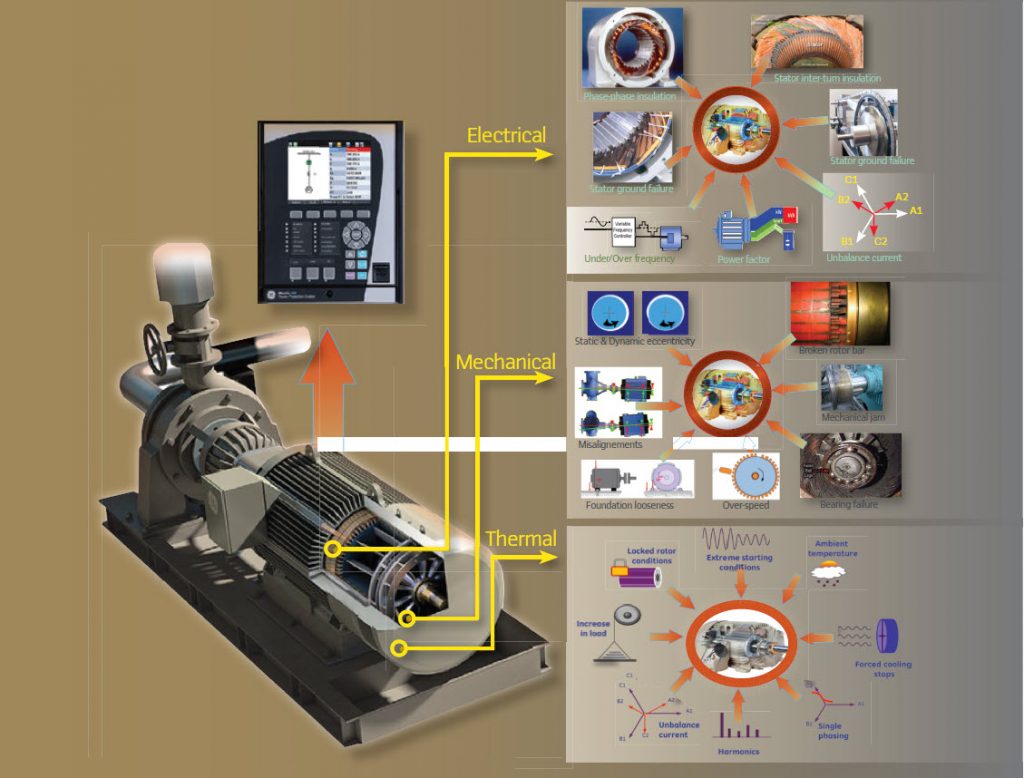
Traditionally, although protection relays may witness the evolution of a machine failure, no action is taken since the primary job of the relay is to react (in terms of an alarm or trip) on detection of the failure or damage. To achieve proactive machine asset management, electric machine failure modes are categorized into three streams: Mechanical, Electrical and Thermal shown on page 38.
Electrical abnormalities and failures related to Stator inter-turn insulation failure can be detected before they evolve into phase or ground faults. Furthermore, proactive electrical functions are applied using multiple flexible elements, such as: i) capture duration and the number of unbalance currents and voltages; ii) slowly increasing trends in sensitive ground currents; iii) power supply quality; iv) motor loading/operating profiles; etc.
Once the winding insulation deteriorates, it generally results in an inter-turn fault involving a few turns of the winding within the same phase to ground or different phases. The fault current causes severe localized heating and the damage rapidly spreads to a larger section of the winding. If the insulation deterioration is detected at an early stage, shutdown of the machine can be planned, and appropriate actions can be taken.
Proactive functions for many mechanical abnormalities can be achieved using Electrical Signature Analysis (ESA), also known as Motor Current Signature Analysis (MCSA). ESA is based on sensing stator current components at specific frequencies which are a direct by-product of unique rotating air-gap flux components. These are caused by faults such as bearing anomalies, static or dynamic eccentricity, shaft misalignments, foundation looseness, and broken rotor bars using advanced Fast Fourier Transform (FFT). There is no need for additional sensors or probes as mechanical failure algorithms based on ESA use the same 3-phase stator currents from the current transformers fed into the protection IEDs. Industrial application experiences of such techniques are shared in the book “Current Signature Analysis for Condition Monitoring of Cage Induction Motors” by William Thomson and Ian Culbert, and various journal publications.
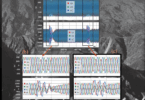
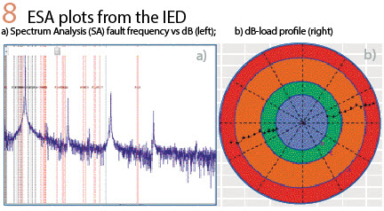
Used over a few decades, ESA techniques are currently applied using portable test-sets or spectrum analyzer for period testing or standalone devices for continuous monitoring. Protection relay can also provide ESA plots as illustrated in Figure 8. The first plot, Figure 8-a), provides spectrum (FFT) analysis results of magnitudes (in dB) over the entire frequency spectrum and the red-dotted lines are the frequencies of interest to monitor the failure modes. The circular dB-load profile represents various peak dB level evolutions over the different load bins to compensate for the loading effect.
Summary: With the revolutionary trends in digitization, technology and interoperable multi-vendor process bus systems are enabling future-proof PAC systems with drivers to simplify at the process level, converge at the bay level, and virtualize at the station level. One of the advantages of simplifying process bus with virtual isolation and automated testing of PAC function is discussed in this article. Furthermore, with the availability of data over open standard protocols will allow innovative proactive protection applications in the industry. Although advancements in technology allow high-speed (MHz) signal processing, ultra-speed protection functions, these functions primarily protection upon detection of the damage. In many cases, an unscheduled outage by a reactive protection IED causes huge loss of revenue for the power utilities. Proactive functions for transformer, breaker/switchgear, and rotative machines can be used for condition-based maintenance, asset performance management, asset risk mitigation, early warning/alarming, and well-informed root cause analysis. Integration of transformer chemical analysis (e.g. DGA) and electrical analysis, and switchgear thermal (e.g. temperature) to electrical correlation analysis provide opportunities to facilitate better primary equipment asset condition monitoring.
Biographies
Mital Kanabar is a Senior R&D-Applications Engineering Manager (D&I) at General Electric; and adjunct Professor at the University of Ontario Institute of Technology (UOIT), Canada. He as a Ph.D. from the University of Western Ontario, M.Tech., from the IIT Bombay, India. Mital has 8 years of industrial R&D experience. He is currently vice-chairing the IEEE PES PSRC WG C19 on PDC standard; and WG K15 on centralized substation Protection and Control. He is an active member/contributor of many technical WGs at IEEE PSRC, CIGRE, NASPI, and IEC. He holds 8 international patents, and is the author of 40 papers and 3 magazine articles.
Jeff Mazereeuw is the CTO for GE Grid Automation with over 30 years of experience in power system controls. He began his career in protection and control. Jeff was the program manager for the Universal Relay – launched in 1998 with Ethernet and UCA 2.0 protocol (a precursor to 61850). Today, he leads the global R&D team that develops products and services to operate, manage, protect and control power systems. Jeff has written numerous IEEE papers and holds 10 patents. Jeff also holds an MBA from Queens University in Kingston, Ontario.