by Walter Schossig, Germany, and Thomas Schossig, OMICRON electronics GmbH, Austria
As already discussed, the impact of standardization increased in the 1950s. More and more regulations and recommendations have been published. For instance, in Western Germany the association of utility companies (VDEW) installed a board on “standards and rules.”
The intention was to develop guidelines for the new relays released after the war. Operation and mode of action should be unified. Taking into account the experiences from the time before the war, that the collaboration of protection systems in neighbored grids did not always work without issues.
The utilities demanded interoperability of the protection devices among the different vendors. Several meetings took place to push this. Guidelines to be published considered future developments such as under impedance startup. This shall allow a certain overload of the lines on the one hand side but allow the detection of doubled earth faults with huge distance in between, resulting in low short circuit currents. The agreement was a setting range for the current between 0.5 – 1.0 of nominal current in case of zero voltage.
For the full voltage (100 V) the range was defined as 0 – 3 of nominal current. The curves shall show not just the impedance but the voltage as a function of current. For the huge transmission systems, a combination of under impedance and overcurrent was rated as useful. On the directional elements they should start properly with a voltage of 0.1 V and bigger. If the relays tripped within the dead zone (in case of busbar protection) simultaneously, the dead zone itself was not so important at all. There was no need, to decrease the time set.
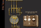
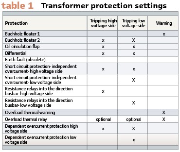
Table 1 shows the settings recommended for transformer protection.
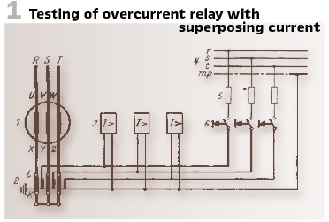
A simple test setup with overlay current is shown in Figure1. The test buttons overlay a current to the operational current. Via the resistance 5 the value can be set. Pressing 6 injects an additional current. To avoid false tripping of the generator, the tripping connections of generator and de-excitation circuit breaker are interrupted. Measurement devices show values of current, voltage and time. There was no need for additional wiring.
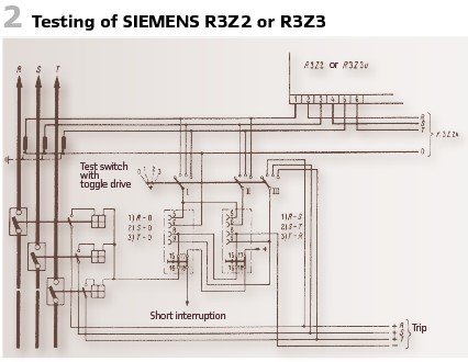
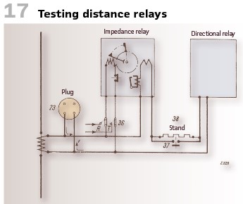
How to connect the distance relays R3Z2 or R3Z3 (Siemens) is shown in Figure 2.
Also, here testing plugs in combination with test switches were used. The proper operation of the relay was tested with overlay current again. In case of full nominal voltage, taking into account the direction of the current, the end time (directional and nondirectional) will be reached. An additional test switch is taking the voltage from the distance protection but not from the under-impedance element. This allows testing of fast time stage. The minus potential is connected via auxiliary contact.
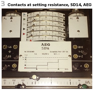
AEG’s SD14 showed the secondary impedance values in a simple manner. The setting elements are marked in colors (Figure 3).
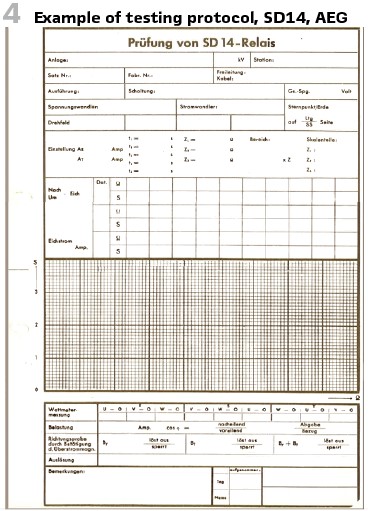
Looking into the manual, there was no maintenance necessary for this relay. Nevertheless, during putting into operation and from time to time (every 6 months) or after changes of settings a test was recommended. Figure 4 shows a German example of such a test report. It contains the technical values as well as a curve Z=f(t), to be drawn utilizing a pencil. With colors measured values and defined values should be compared.
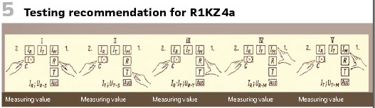
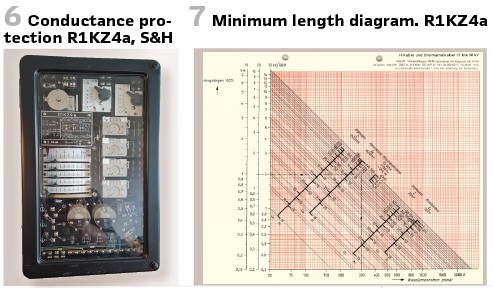
S&H’s conductance protection R1KZ4s (Figure 6) also came with a testing recommendation (Figure 5).
At first the auxiliary relay R and after this C had to be pressed by hand. The directional relay had to be observed at this time. Later the relay T, after this R and T had to be pressed. Doing so, the current circuit was short circuited. In that case the directional element could be tested as well.
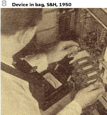
For a 5A-relay the smallest measuring value was 0.05 Ω/phase. As a support there was a diagram with the maximum length. For a 120 mm2 H-cable at 300/5-A-CT und 20.000/100 V VT the minimum length was 1.3 km (Figure 7)
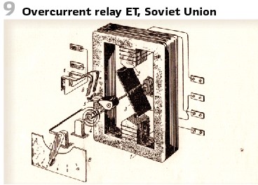
Irregularities noted during commissioning and routine testing have been caused by measurement wirings and other external elements. For the portable measurement devices, there was no place to store them. That’s why additional boxes, bags, cables and equipment have been delivered with the device (Figure 8).
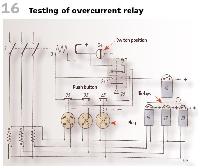
Also, in the Soviet Union a lot of development was done. One of the most important books at this time was W.E. Kasanski’s book on relay protection (,1950). Regarding the testing for an overcurrent relay ET (Figure 9) he recommended as follows.
For the test it is mandatory to check the characteristics. Additionally, a mechanical check for new relays is essential. Refurbished relays had to be checked in the lab. After the tests the relay was sealed. The mechanical check contained a lot of steps:
- Cleanness of the mechanisms, contacts and housing
- Removing dusts, small fragments at the disks
- Checking the tapers and screws
- Proving the weight of mechanical elements
- Checking the spring
- Checking the isolation with mega ohm meter at a voltage of 1000 V
- Checking the contacts and all the angles
- Checking the moving parts
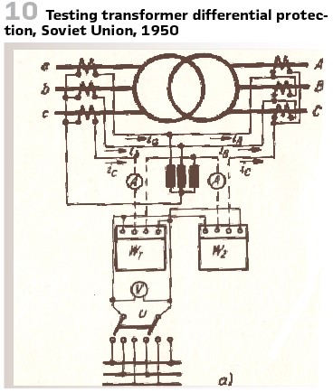
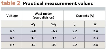
The setup recommended for testing transformer differential protection is shown in Figure 10. The test was done phase by phase. The figure shows testing of phase C. The switching device allows the connection of the watt meter to the different phases. Grid’s voltage must be similar as watt meter’s nominal voltage. For the voltage a transformer was used After switching on the primary current source the currents ic and iC could be measured. If they are almost equal, the switch U connects the phases a- and b to the watt meter. After this the other phases can be switched. If everything was done properly the measurements in both watt meters must deliver the same value. (see Figure 10). In a practical measurement the values shown in Table 2 have been the results. So, the difference between the watt meter’s scales is 5% and fine.
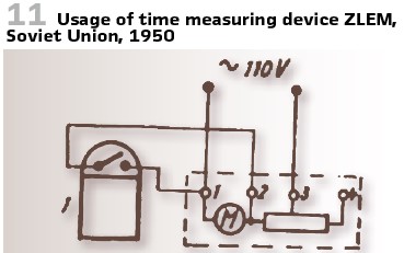
To measure the time the device ZLEM was used (see Figure11).
By switching on the 110 V or 220 V are connected to the synchronous motor. When the relay trips, the motor stops, and the value can be measured. The display depends on the frequency. If the value is not 50 Hz, there is a need to multiply by (50 Hz)/f. In the example above there was a measurement of 4.5 s at 45 Hz. So, the real time is 4.5 s (50 Hz)/(45 Hz) = 5 s.
A protection test, which does not in every case demands protection engineers is the Buchholz test. This can be done by the operating people. In Eastern Germany the ministry for coal and energy recommended in 1956, to test the Buchholz relay with air pump (warning floater) and pen (tripping floater). This shall be done every 6 months. After a trip of a transformer the isolation has to be measured. Gas collected shall be investigated. Only if the gas is not flammable and the transformer’s test showed no failure, it was allowed to switch on again. Fritz Ande wrote his book on “Control and application of power transformers and variacs” in 1954. Also, he recommended to pump oil into the Buchholz relay to test the warning. To test on loss of oil the butterfly valve to the extension vessel shall be closed. Now the oil can drain, and the level can be observed. Then the warning shall appear.
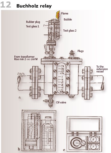
Figure 12 shows Buchholz relay with gas testing device connected. The bottles contain silver nitrate. White dregs indicated oil gas, brown or black color showed carbon.
The Buchholz relays have been already tested in the factory. Also, here the speed of detection, the inherent delay and the amount of oil suppressed have been important values. Additionally, isolation, impermeability and mechanical stability were important.
Figure 14 shows a SIEMENS test setup.
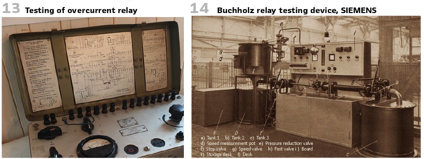
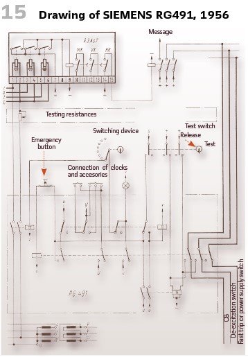
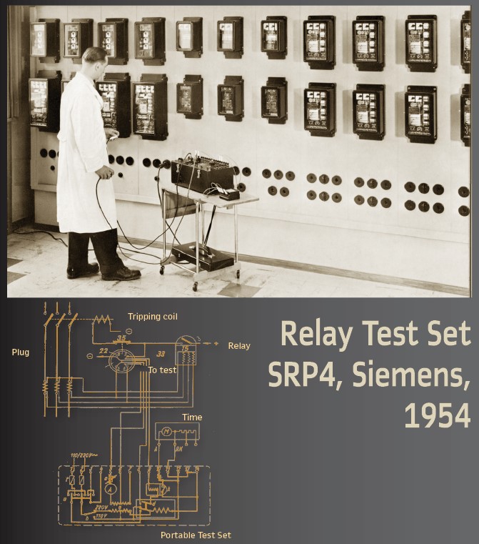
Figure 13 shows the portable relay test set by SIEMENS SRP4. Later its name was changed to 7VP44. The cap contained drawings and allowed the testing engineer easy setup of any test (Figure 16, Figure 17, Figure 19)
The overview scheme shows the relay under test R. the switchable transformer 110/ 220V, secondary 0—60V; 0-25V. The other part of the winding could be used for smaller currents (voltage divider 0 – 20 V, 0 – 2.5 A and measurement devices with 2 scales. The test plug must be inserted with a minor rotation. This was done to avoid unplugging before the reset of the relay.
At the end we want to have a look into so called “secondary test setups.” This term appeared in a paper on generator protection relays by Erwin Zurowski. He identified two different applications. One was portable and the other for stationary usage.
The portable test set will be used when the station contains a small number of similar relays. For instance, impedance protection or overcurrent relays protecting a line feeder. In such cases test plugs have been prepared. The test set injects directly, the tripping circuit is interrupted at this time. At this time portable test sets have been single phase devices. In case of wide range of relays protecting huge machines, a testing possibility within the protection field makes sense. In that case the three-phase machine voltage can be used.
 |  |
This also guarantees that the phase shift between testing current and operating current is guaranteed. In such a case a single switching device during test is sufficient. The testing itself runs as with the mobile device.
The tripping circuits are interrupted by door contacts or switches. The relay receives the testing current via pushbuttons. In both cases the duration of tests as well as reliability depend on engineer’s capabilities.
To guarantee availability of the relay during the test, the testing time shall be as small as the response time of the relay. The relays at this time operated with 0.1 s. So, the testing time shall be some 10 ms only. Also, the reset of the test set shall be faster than the startup of the relay.
Another important requirement was the reliability to be guaranteed during all possible cases at the device under test. They identified two reasons: a) relay does not start up, even if the current injected is big enough. b) Relay starts up, but no reset.
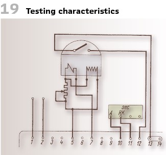
Figure 15 shows the setup of a testing device, fulfilling the demands.
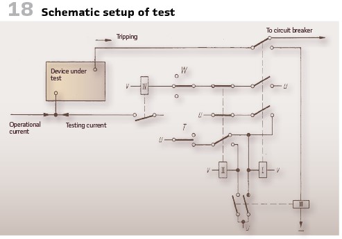
The schematic operation was as follows (Figure 18).
Every protection to be tested is assigned with a relay IV (via test switch). The testing starts, via a normally closed contact of relay II relay I goes into catch. At the same time the tripping circuit will be interrupted. This guarantees no false tripping of the circuit breaker. Another contact of relay II connects relay I and voltage to relay IV. Relay 4 connects the current to the device under test. The trip signal operates relay III, excites relay II and catches relay I. Relay II brings relay IV to open, the device under test resets.
info@walter-schossig.de www.walter-schossig.de
thomas.schossig@omicronenergy.com
Biographies:
Walter Schossig (VDE) was born in Arnsdorf (now Czech Republic) in 1941. He studied electrical engineering in Zittau (Germany) and joined a utility in the former Eastern Germany. After the German reunion the utility was renamed as TEAG, Thueringer Energie AG in Erfurt. There he received his master’s degree and worked as a protection engineer until his retirement. He was a member of many study groups and associations. He is an active member of the working group “Medium Voltage Relaying” at the German VDE. He is the author of several papers, guidelines and the book “Netzschutztechnik [Power System Protection].” He works on a chronicle about the history of electricity supply, with emphasis on protection and control.
Thomas Schossig (IEEE) received his master’s degree in Electrical Engineering at the Technical University of Ilmenau (Germany) in 1998. He worked as a project engineer for control systems and as a team leader for protective relaying at VA TECH SAT in Germany from 1998 until 2005. In 2006 he joined OMICRON as a product manager for substation communication products. He is author of several papers and a member of standardization WGs.