by Rannveig Løken, Statnett, Norway
Statnett use frame agreement with a few vendors to ensure uniform Protection, Automation and Control Systems (PACS) on a proven basis of a pilot project. Statnett have requirements to Protection, Automation and Control Systems in the specification that the vendor must fulfil. The vendors adapt their solution to fulfil the requirement from the specification.
Statnett uses a system called Control server to store the documentation for all the substations. The system is developed in cooperation with the vendor for each frame agreement system. All the programs needed to operate the IEC 61850 control system are stored on the Control server for each vendor specific solution.
Development towards Frame agreement for PACS
Before we started with the frame agreement, there would be a slightly modified system for each new substation project. For each project we had a specification that would state the functions we needed and how the system should be built up according to Statnett’s Documentation of Principles. After a while we realized that the systems were not the same even if the same vendor was used, because there had been a development in the Protection, Automation and Control Systems with new software versions and maybe also new hardware versions. It was a big challenge for us to maintain each system with a number of variations from one Protection, Automation and Control Systems to another. The idea of the frame agreement for Protection, Automation and Control Systems, started from type acceptance of protection. The main reason was to have a better control of the development and maintenance aspect of the whole Protection, Automation and Control Systems. There was a need to have a standard solution for the whole Protection, Automation and Control Systems that would last for more than one project.
Cigre Working Group B5.27 “Implications and Benefits of Standardized Protection and Control Schemes” has given some good advice on how to standardize the PACS in a utility.
Statnett have for the last decade developed frame agreement with a few vendors to ensure uniform Protection, Automation and Control Systems on a proven basis of a pilot project. The PACS is based on IEC 61850 standard. The system allows interoperability between Intelligent Electronic Devices (IEDs) of different vendors in one utility PACS. To avoid problems regarding changes in the PACS in the future, the utility must ensure a robust specification and a unique cooperation with the vendor during the engineering of the system development.
This article will present some of Statnett’s experience using frame agreement for our Protection, Automation and Control Systems. It will also address the requirement for the protection in the specification and the use of acceptance test to evaluate the functionality of new protection functions. It will cover the Control server solution used to standardize the maintenance of our Protection, Automation and Control Systems.
Standardization Using Frame Agreement for PACS
The technical specifications describe Statnett’s requirements for the Protection, Automation and Control Systems (PACS) functionality and equipment. The technical specifications refer to Statnett’s applicable documentation of principles. The documentation of principles provides a detailed representation of the control system’s functionality, connections and signal exchange. The control system includes all necessary functions such as protection, control, regulation, measurement, indications and communication. These features are necessary to ensure safe and optimized grid operations, to protect life and property, and to collect data for use in analyses, billing and statistics.
Statnett have based the requirement in the specification for the frame agreement on experience from previous projects. The frame agreement includes the vendors solution to the technical requirements in the specification from Statnett. The solution for the Frame agreement from each vendor is documented and tested in a pilot project. This includes the required functionality of the system by means of specifications and verifications from start to finish of a PACS substation project.
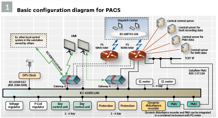
Figure 1 shows the basic configuration diagram for Protection, Automation and Control System (PACS) in Statnett.
The Standard developed in the first pilot project will determine the layout and design of all the projects delivered by the vendor during the Frame agreement period. During a frame agreement period the vendor deliver the same versions of system software, firmware versions and configuration and parameterization tools for all deliveries.
Cigre Working Group B5.31 “Life-time Management of Relay Settings” have given some advice on how to update software and firmware in a PACS system.
General Line Protection Requirements
In the specification for the Protection, Automation and Control system in the frame agreement there is a requirement to the different part of the system. One of the important parts is the general line protection requirement. A short description of the functional requirements is shown in this part of the article.
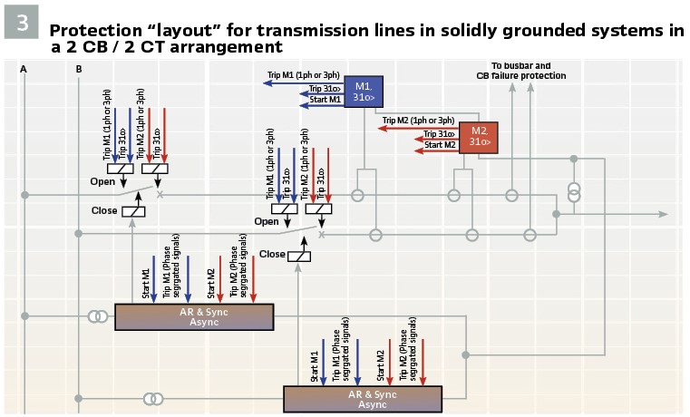
The total fault clearing time including opening time of the circuit breaker must not exceed 100 ms for faults on transmission lines in the solidly grounded system. To achieve this requirement Statnett uses two separate protection systems (Main1 and Main2) with two fully independent fiber optic communication channels, one for Main1 and one for Main2, for signal transmission between teleprotection functions.
Tripping arrangement is one out of two. Both Main1 and Main2 release trip commands (single-or three-phase trip) to each trip-coil at each circuit breaker. Each circuit breaker has separate autoreclose (AR) and synchronizing function and circuit breaker failure relay included in the busbar protection. Trip command from short-circuit protection functions in Main1 and Main2 starts both AR-functions and both circuit breaker failure relays.
To have two fully independent protection systems, each protection system also has independent DC-supply. A principle drawing of a 2 CB / 2CT line bay is shown in Figure 3. In general, all protection functions shown in Figure 1 must be in separate devices, but the non-directional earth-fault overcurrent protection (3I0>) shall be integrated in both Main1 and Main2. The AR- and synchronizing function for both circuit breakers can be integrated in the bay control unit.
Requirements to Distance Protection Function
Another part in the specification for the Protection, Automation and Control system in the frame agreement is the requirements to distance protection function.
To achieve the 100 ms requirement, maximum operating time from distance protection function including transmission time delay for carrier send/receive (Teleprotection, echo, WEI-trip and current reversal) must not exceed 40 ms. Independent of system grounding distance protection must have minimum 5 fully independent full-scheme quadrilateral zones with independent settings for zone direction, reach in resistive and reactive direction and time delay.
Statnett use single-phase trip/AR for single phase faults and three-phase trip/AR for multi-phase faults. Therefore, the distance protection function must have a phase selection logic and trip logic which clearly discriminate between single-phase and multi-phase faults. The directional determination logic must be able to decide correct direction to both single and multiple faults even in case of CT-saturation in inductive as well as in series compensated transmission systems.
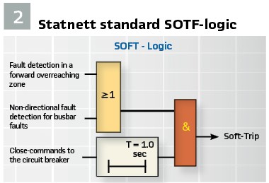
Statnett do not use any vendor-specific switch onto fault logic (SOTF). Instead Statnett use a SOTF-logic as shown in Figure 2. This SOTF-logic is included in both Main1 and Main2.
Pole discordance protection function and logic for trip-initiated system protection is always included in both Main1 and Main2. Distance relays used in non-earthed systems must have functionality to be used also in solidly grounded systems in case of future change of system grounding to solidly earthed system.
In addition, distance protection used in non-earthed systems must have logic for suppression of trip command in case of single phase to ground faults and a phase preference logic for detection and correct release of trip command in case of cross-country earth-faults must be included. Line bays in compensated/isolated network shall have transient earth fault relay (Wischer-relay) for detection of the direction to permanent earth faults.
The relay shall have indication signals for earth faults in both forward and backward direction. There is an advantage if the Wischer-function is included in the line protection.
Evaluation of New Protections in Acceptance Test
During the past decade Statnett has performed acceptance tests of new numerical protection functions. The purpose of these tests is to get sufficient information about the different functions to fully evaluate whether they are applicable or not as protection functions for critical components in our power system. To limit the number of acceptance tests, only new numerical protection functions that protects critical components in our power system (i.e. lines, transformers, shunt reactors and busbars) have to pass through a complete acceptance test. This includes the following protection devices:
- Busbar protection with integrated circuit breaker failure protection
- Differential protection function and restricted earth fault protection function for autotransformers, two- and three-winding transformers and differential protection function for shunt reactors
- Distance protection function
- Line differential protection function for two or more-line ends
- Automatic reclosing and manual closing device for lines, transformers, bay coupler, etc.
- Directional overload protection (system protection)
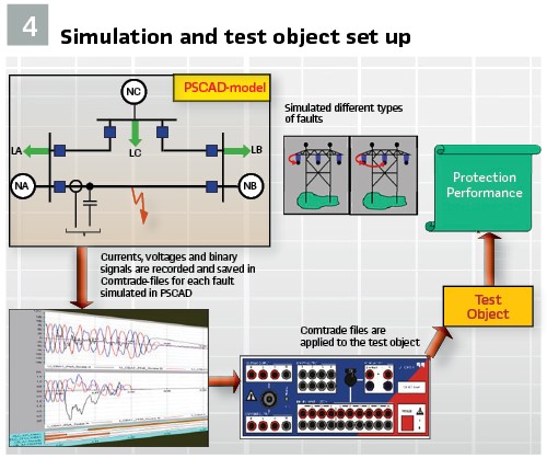
Accomplishment of acceptance tests has shown that this is the most efficient method to obtain sufficient knowledge about actual performance for all relevant protection functions. The acceptance test focuses on the complete functionality of new numerical protection devices. By functionality we mean to what extent the different protection functions can be configured and set and as a result of this, be used as protection for critical components in our power system. Statnett has modelled different power systems in the well-known transient simulation package PSCAD.
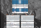
The models cover actual power system phenomena’s and relevant contingencies for evaluation of protection performance. At potential protection locations, outputs like voltages, currents and relevant sets of binary signals are recorded and saved as COMTRADE files as shown in Figure 4. For different types of protection, all important contingencies are simulated, including internal and external faults. Pre fault, fault, post fault and all types of reclosing sequences are simulated in detail. Saved COMTRADE files are then loaded into a numerical test device and applied to test objects exposed for acceptance testing. (see Figure 4).
The actual protection performance is then evaluated in detail. The acceptance test includes four different steps. Statnett have a set of documents, which summarize Statnett requirements to the different protection functions mentioned.
- In the first step these documents are used when evaluating the functionality of actual protection functions by reading manuals, presentations and discussions with a vendor. This step will also include an evaluation of the PC-software tool used for configuration, parameter setting, disturbance handling, etc. based on Statnett requirements. If the overall information seems to fulfill Statnett requirements to the different protection functions, Statnett continue with the next step 2 otherwise no acceptance test is performed.
- In the second step the vendor receives necessary power system data including data for the protected object, information about different types of faults and all types of reclosing, expected action from the test object, etc. from Statnett. Based on this information and information given in the first step, the vendor is fully responsible for parameterization and configuration of necessary protection functions within the test object. Statnett does not change vendor’s settings! The complete parameterized and configured test object including the PC-software tool is handed over to Statnett.
- During the third step, relevant sets of COMTRADE-files are applied to the test object. Vendor normally delivers the protection(s) to Statnett during this test phase. In some cases, Statnett have used vendors test facilities. The actual protection performance for all protection functions are evaluated in detail with use of internal fault- and event recorder and compared with ‘expected action.’
- In the fourth and last step all results are studied in detail, and Statnett conclude whether or not the test object is applicable for use as protection for critical components in our power system. Statnett presents and discusses the test results with the vendor. If the acceptance test is successful, Statnett standardize the accepted firmware for the frame agreement period.
During the frame agreement period a vendor may discover the need for corrections in protection algorithms and release a newer firmware than accepted by Statnett. Before Statnett can accept use of a newer firmware version for an already accepted protection function we must receive documents from the vendor with a detailed description of the new functionality and why it has been implemented. Based on carefully reading of the received information and discussions with vendor (if needed), Statnett decide if we continue using the already accepted firmware version or start using the latest firmware version with/without running through a limited or complete acceptance test.
Standardization Using Maintenance System
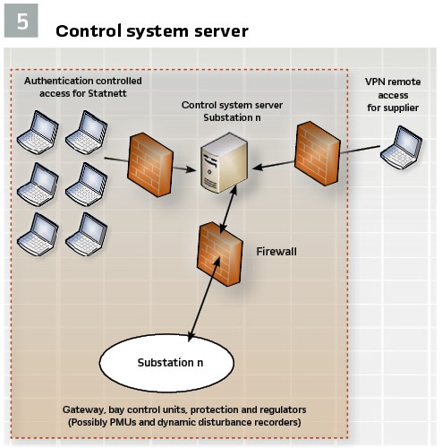
Statnett use a system called Control system server to store the documentation for all the substations. The system is developed in cooperation with the vendor for each frame agreement during the pilot project. All the programs needed to operate the IEC 61850 control system are stored on the Control server. The vendors use their own tool for documenting the PACS.
The Control server is used as the maintenance portal to the control system and for remote diagnosis of the system. This makes it possible to locate the fault on a system down to e.g. the I/O card of a bay controller. The maintenance personnel can then more efficiently repair the system and regain operation.
It is possible to communicate with all protection, controllers and any dynamic disturbance recorders connected to the system’s IEC 61850 LAN from the Control servers located at Statnett. Statnett networks are used for communications between Control servers and IED’s in the substation. Communication with the Control servers does not affect the devices’ functionality.
The original software for the Digital Substation Automation System, including system specific configurations, is stored on the Global system server. After Factory Acceptance Tests (FAT) all configuration and parameter changes in the control system is performed via software installed on the Control server both when working locally in the substation and from remote workstations. This requires high speed access to all substations to avoid unacceptable delay times. With a 2 Mb or more line the difference between working locally and from remote is negligible.
The vendors are given a few Statnett computers they can use to communicate with the Control server from the substation or their office after the FAT.
There is a signed agreement with the vendors on how to use the system to ensure there will not be changes on a system that has been put into service. (see Figure 5).
Standardization of Testing Procedures
The first system delivered in a frame agreement is defined as a pilot installation and is subject to extended testing. The pilot installation will ideally test all equipment and systems solutions. The pilot installation tests are conducted on the most complete system configuration possible and on the physical equipment that will be delivered for the system. The pilot installation is a real substation that will be put in operation after the pilot testing.
In case of major changes in firmware, operating system, functions not delivered in the first project there might be extended testing after the original pilot installation is delivered.
The master test plan describes the systems and functions that will be tested and in which test phases this will be done. The master test plan forms the basis for the scope of testing for: IAT (internal acceptance tests), FAT (factory acceptance tests) and SAT (site acceptance tests) phases for future deliveries. The test plan describes the scope of the testing including the systems and functions that will be tested. It also includes the purpose of each test in general terms and how discrepancies and faults detected during FAT and SAT will be recorded, followed up and corrected. The test procedures describe in detail, and specify the purpose of each test and include a detailed description of the test environment and equipment that will be used during the tests, test identification number (serial number), test name and description, division of each test into logical steps, a detailed description of how each test shall be carried out and a description of the expected system response for each step. The pilot tests will confirm that configurations, settings, communication, interoperability and system behavior are acceptable.
High load tests are performed during pilot tests to verify system behavior and response time. Some of the system behavior that is studied includes how the IEC 61850 communications is optimized to avoid unnecessary data traffic. The internal fault recorders in protection relays with group start requires a lot of data to be transmitted on the station bus and on the communication lines from station to Supervisory Control and Data Acquisition (SCADA). The traffic from fault recorder or other non-critical traffic will be delayed until the network disturbance is cleared and must be given lower priority than the SCADA communication.
Benefits of Standardizing the PACS
A standardized configuration is a harmonized configuration when it comes to the Protection, Automation and Control System functionality implemented. The most obvious standardization is to use protection functions configured in a specific way but also for example naming of disturbance recorder signals, hardware channels and LED’s.
There are several benefits to using standardized configurations:
- Tested configurations: The diversity of configurations is reduced. The ones used are uniform and tested meaning that the need for support is minimized
- Uniform configurations: When support from vendor is requested, the standardized configurations are essential since fault tracing is kept simpler due to the fact that certain sources of the problem can be ruled out. For example, a vendor knows that the configuration is working and can focus on identifying hardware related or surrounding system problems
- Product upgrades: Since the vendor knows how their products are used and not only which products are used, recommendations when it comes to product upgrades are easier and safer to do
- Perceived product quality: Since the vendors’ products are used and configured in a standardized, tested way, the handling and perception of the products is easier making the perceived product quality higher
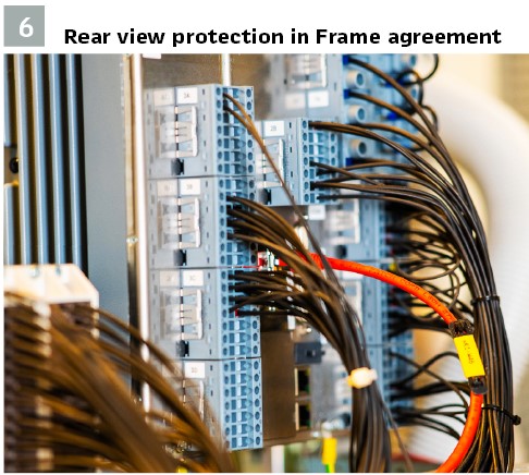
The vendor delivers the same versions of the system software, firmware versions and configuration and parameterization tools for all deliveries made during the term of the frame agreement. This makes the operation and maintenance easier for Statnett. If a problem is discovered in the software that may affect the delivered system’s functionality, the vendor will specify the need for and carry out testing in connection with upgrading software in already delivered systems. Statnett shall determine whether or not the upgrading shall be carried out. (see Figure 6).
Because of the benefits, Statnett use frame agreements for Protection, Automation and Control System with a few vendors to ensure standardized and uniform PACS on a proven basis of a pilot project.
Statnett has good experience using frame agreement for Protection, Automation and Control System. It focuses on the protection requirement and acceptance of vendor product used to standardize the solutions for the Protection, Automation and Control System. The cooperation between Statnett and the vendors have resulted in protection functions that are according to requirements and a success for both parties.
Biography:

Rannveig J. S. Loken received her Bachelor of Science in Microelectronics from Trondheim University College in 1990, and her Master of Science in Electric Power engineering from the Norwegian University of Science and Technology (NTNU) in 1992. She works in Statnett, the TSO of Norway, and has been the Head of Section for the Control and Protection system since 2007. In August 2012, she became the secretary of Cigre SC B5. Her special field of interest is protection and control for the transmission system. She is currently the project manager in Statnett for a R&D project related to Digital substation. Working in Cigre Working groups is of great interest – she is currently a member of WG B5.53. Rannveig is in the Advisory board of PAC world, Committee member of DPSP, and Member of the International Advisory Committee APAP.